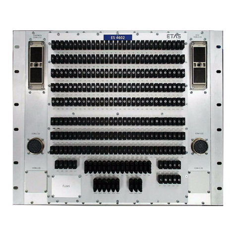
ETAS ES1222.2-A User manual

Artisan Technology Group is your source for quality
new and certied-used/pre-owned equipment
• FAST SHIPPING AND
DELIVERY
• TENS OF THOUSANDS OF
IN-STOCK ITEMS
• EQUIPMENT DEMOS
• HUNDREDS OF
MANUFACTURERS
SUPPORTED
• LEASING/MONTHLY
RENTALS
• ITAR CERTIFIED
SECURE ASSET SOLUTIONS
SERVICE CENTER REPAIRS
Experienced engineers and technicians on staff
at our full-service, in-house repair center
WE BUY USED EQUIPMENT
Sell your excess, underutilized, and idle used equipment
We also offer credit for buy-backs and trade-ins
www.artisantg.com/WeBuyEquipment
REMOTE INSPECTION
Remotely inspect equipment before purchasing with
our interactive website at www.instraview.com
LOOKING FOR MORE INFORMATION?
Visit us on the web at www.artisantg.com for more
information on price quotations, drivers, technical
specications, manuals, and documentation
Contact us: (888) 88-SOURCE | sales@artisantg.com | www.artisantg.com
SM
View
Instra

ES1222.2-A
CAN + K-Line Board
User’s Guide
Artisan Technology Group - Quality Instrumentation ... Guaranteed | (888) 88-SOURCE | www.artisantg.com

2 ES1222.2-A CAN + K-Line Board
Copyright
The data in this document may not be altered or amended without
special notification from ETAS GmbH. ETAS GmbH undertakes no
further obligation in relation to this document. The software descri-
bed in it can only be used if the customer is in possession of a gene-
ral license agreement or single license. Using and copying is only
allowed in concurrence with the specifications stipulated in the con-
tract.
Under no circumstances may any part of this document be copied,
reproduced, transmitted, stored in a retrieval system or translated
into another language without the express written permission of
ETAS GmbH.
© Copyright 2000 - 2002 ETAS GmbH
The names and designations used in this document are trademarks
or brands belonging to the respective owners.
Document QH122201 R1.0.3 EN TTN F 00K 700 568
Artisan Technology Group - Quality Instrumentation ... Guaranteed | (888) 88-SOURCE | www.artisantg.com

Contents 3
Contents
1Introduction . . . . . . . . . . . . . . . . . . . . . . . . . . . . . . . . . . . . . . . . . . . .5
1.1 Features . . . . . . . . . . . . . . . . . . . . . . . . . . . . . . . . . . . . . . . . .5
1.2 Applications . . . . . . . . . . . . . . . . . . . . . . . . . . . . . . . . . . . . . .7
1.3 Block Diagram . . . . . . . . . . . . . . . . . . . . . . . . . . . . . . . . . . . . .8
2Hardware . . . . . . . . . . . . . . . . . . . . . . . . . . . . . . . . . . . . . . . . . . . . . .9
2.1 Functional Description . . . . . . . . . . . . . . . . . . . . . . . . . . . . . . .9
2.1.1 Interfaces . . . . . . . . . . . . . . . . . . . . . . . . . . . . . . . . .9
2.1.2 CANbus Data Acquisition . . . . . . . . . . . . . . . . . . . .11
2.1.3 Analog Output . . . . . . . . . . . . . . . . . . . . . . . . . . . .11
2.1.4 Ipetronik Modules . . . . . . . . . . . . . . . . . . . . . . . . .11
2.2 Firmware Update . . . . . . . . . . . . . . . . . . . . . . . . . . . . . . . . . .12
2.2.1 Connectors. . . . . . . . . . . . . . . . . . . . . . . . . . . . . . .12
2.3 Hardware Configuration . . . . . . . . . . . . . . . . . . . . . . . . . . . .12
2.3.1 Jumpers JP1-JP3 . . . . . . . . . . . . . . . . . . . . . . . . . . .13
2.3.2 Jumper JP1000. . . . . . . . . . . . . . . . . . . . . . . . . . . .13
2.4 Pin Assignment . . . . . . . . . . . . . . . . . . . . . . . . . . . . . . . . . . .14
2.4.1 Lemo CAN1-CAN4 . . . . . . . . . . . . . . . . . . . . . . . . .14
2.4.2 K-Line/L-Line. . . . . . . . . . . . . . . . . . . . . . . . . . . . . .15
2.5 Technical Data . . . . . . . . . . . . . . . . . . . . . . . . . . . . . . . . . . . .16
Artisan Technology Group - Quality Instrumentation ... Guaranteed | (888) 88-SOURCE | www.artisantg.com

Contents4
2.6 Accessories and Order Numbers . . . . . . . . . . . . . . . . . . . . . . 18
2.6.1 CAN Interface Cable (ES1222-A) . . . . . . . . . . . . . . 18
2.6.2 CAN Interface Cable (ES1222-A) . . . . . . . . . . . . . . 18
2.6.3 CAN Interface Cable . . . . . . . . . . . . . . . . . . . . . . .19
2.6.4 CAN Termination Plug 120 Ohm . . . . . . . . . . . . . . 19
2.6.5 CAN Termination Connector . . . . . . . . . . . . . . . . . 19
2.6.6 CAN Interface Cable SIC - DSUB. . . . . . . . . . . . . . . 20
2.6.7 VCAN Interface Adapter. . . . . . . . . . . . . . . . . . . . . 20
2.6.8 K-Line Interface Cable (KIC, MAC2) . . . . . . . . . . . .21
2.6.9 Cable Adapter (KIC, MAC2, SIC) . . . . . . . . . . . . . . 21
2.6.10 Cable Adapter . . . . . . . . . . . . . . . . . . . . . . . . . . . . 22
2.6.11 Cable Adapter for K-Line Extension . . . . . . . . . . . . 22
3Glossary . . . . . . . . . . . . . . . . . . . . . . . . . . . . . . . . . . . . . . . . . . . . . . 23
List of Figures. . . . . . . . . . . . . . . . . . . . . . . . . . . . . . . . . . . . . . . . . . 25
List of Tables . . . . . . . . . . . . . . . . . . . . . . . . . . . . . . . . . . . . . . . . . . 27
Index . . . . . . . . . . . . . . . . . . . . . . . . . . . . . . . . . . . . . . . . . . . . . . . . 29
Artisan Technology Group - Quality Instrumentation ... Guaranteed | (888) 88-SOURCE | www.artisantg.com

Introduction 5
1Introduction
This section contains information about the basic features and appli-
cations of the ES1222.2-A board. A block diagram shows the sche-
matic layout of the board.
1.1 Features
The ES1222.2-A board has four CAN interfaces as well as a K-Line
and L-Line interface. A VME64x interface enables integration to
VMEbus systems, such as the ES1000 system. The board makes it
possible to access serial ECU interfaces.
The ES1222.2-A board has the following features:
•CAN interface
–4 independent, dc decoupled CAN buses
–CAN protocol V2.0a (standard identifier)
–CAN protocol V2.0b (extended identifier)
–CAN Calibration Protocol V2.0/V2.1 (standardized ASAP1a
CCP)
–ISO high-speed physical layer
–baud rates of up to 1 MBit/s can be set using software
–KWP2000 on CAN
•K-Line and L-Line
–conforms to ISO 9141-2 requirements for diagnostic testers
–transfer rates of up to 250 kBaud
–protocols: McMess, KWP2000, Keyword71
•Intel 82C527 and Dallas DS87C520 communication controllers
•Motorola MPC555 with 40 MHz to reduce the system processor
load
–1 MByte SRAM
–1 MByte Flash
note
Some components of the board may be damaged or destroyed by
electrostatic discharges. Please keep the board in its storage package
until it is installed.
The board should only be taken from its storage package, configured
and installed at a work place that is protected against static discharge.
Artisan Technology Group - Quality Instrumentation ... Guaranteed | (888) 88-SOURCE | www.artisantg.com

6Introduction
•independent bus systems for communication controllers and
MPC555
•integrated programming module for generating programming
voltage for Flash EPROMs in ECUs
•ES1222.2-A board firmware can be updated using the BDM
interface
•firmware update of the ES1222.2-A is possible in the ES1000
system via the PC
•extended temperature range for use in the vehicle
(-40 °C to + 85 °C)
•VME64x interface
•connectors suitable for motor vehicles
Artisan Technology Group - Quality Instrumentation ... Guaranteed | (888) 88-SOURCE | www.artisantg.com

Introduction 7
The following figure shows you the front panel of the ES1222.2-A
board.
Fig. 1-1 ES1222.2-A Front Panel
1.2 Applications
You can use the ES1222.2-A board for the following tasks:
•connecting external devices using the CAN interface with
VMEbus systems
•ECU calibration using CANbus and/or diagnostic interface
•ECU diagnostics
•flash programming of ECUs
•measuring external measurands using Ipetronik modules
ES1113
ES1222.2
A
CAN 1CAN 2CAN 3CAN 4
K-Line
Artisan Technology Group - Quality Instrumentation ... Guaranteed | (888) 88-SOURCE | www.artisantg.com

8Introduction
•recording and acquiring communication data in one or more
CAN networks
•simulation of CAN interfaces in CAN networks
1.3 Block Diagram
The following block diagram shows how the ES1222.2-A board
works.
Fig. 1-2 Block Diagram
Both the communication controller and the MPC555 microproces-
sor have their own bus system. The two bus systems are connected
via a buffer.
The VME64x interface contains the buffers for data and address
lines as well as the interrupt logic.
The two dual-ported RAMs can be accessed both from the VMEbus
and the communication controller.
The communication controller makes four CAN interfaces available
as well as the K-Line and L-Line interfaces. Their signals are routed
to the connectors on the front panel via dc decoupling.
DC Decoupling
4 CANbus Interfaces
K- and L-Line
Interface
MPC555
VME64x Slave Interface
Communi-
cation
Controller
SDRAM
16 MB
(64 MB
Extention)
DPRAM
32-bit
128 KB
DPRAM
16-bit
64 KB
Buffer
SDRAM
32-bit
1 MB
FLASH
16-bit
1 MB
Analog
Output
Artisan Technology Group - Quality Instrumentation ... Guaranteed | (888) 88-SOURCE | www.artisantg.com

Hardware 9
2 Hardware
This chapter contains a detailed functional description, information
on hardware configuration and the connectors, and the technical
data of the ES1222.2-A board.
2.1 Functional Description
This section gives you a detailed overview of the features of the
ES1222.2-A board. You will find information on the following sub-
jects:
•interfaces
•CANbus data acquisition
•analog output
•Ipetronik modules
•updating the firmware
•connectors
2.1.1 Interfaces
The ES1222.2-A board has four CANbus interfaces and a serial K-
Line and L-Line interface for connecting VMEbus systems with
external devices.
It also has a communication controller for data exchange via the
serial interfaces. This guarantees high data transfer rates.
Serial CANbus Interface
The ES1222.2-A board has four CANbus interfaces. The CANbus
signals are routed to four 8-pin connectors, CAN1 to CAN4, on the
front panel. The connection to the external device has a maximum
transfer rate of 1 MBit/s (ISO high-speed). The following CAN proto-
cols are supported:
•CAN protocol V2.0a standard identifier (11 bit identifier)
•CAN protocol V2.0b extended identifier (29 bit identifier)
•KWP2000 on CAN
The four CANbus interfaces support the ASAP1a protocol to
guarantee ECU calibration, and the acquisition and monitoring of
CANbus communication data in the vehicle bus.
If you use the ES1222.2-A board for ECU calibration via the CANbus
channels, the ASAP1a protocol has to be implemented in the ECU.
Artisan Technology Group - Quality Instrumentation ... Guaranteed | (888) 88-SOURCE | www.artisantg.com

10 Hardware
Serial Diagnostic Interface
There is a 14-pin K-Line connector on the front panel of the
ES1222.2-A board for connecting the K-Line and L-Line of the ECU
diagnostic interface. The system’s control software determines the
functionality of the K-Line interface of the ES1222.2-A board.
The transfer rate can be a maximum of 250 Bit/s. The transfer rate
and system frequency are set using the control software. The inter-
face supports the following calibration and diagnostic protocols:
•McMess
•Keyword71
•KWP2000
If you use the ES1222.2-A board for ECU calibration with the K-Line,
certain protocols have to be implemented in the ECU:
VME64x Interface
The board has a VME64x interface. The system controller identifies
and configures the address ranges and interrupts once the VMEbus
system has been switched on.
The board can be configured for AutoSlot detection in accordance
with the VME64x specification or the ETAS specification.
Function Protocol
Measuring and calibration McMess or KWP2000 calibration pro-
tocol
Diagnostics Keyword71 and KWP2000 diagnostic
protocols
ECU programming using
flash memory
KWP2000 diagnostic protocol
Artisan Technology Group - Quality Instrumentation ... Guaranteed | (888) 88-SOURCE | www.artisantg.com

Hardware 11
2.1.2 CANbus Data Acquisition
The ES1222.2-A board makes flexible recording and acquisition of
communication data possible, which is exchanged between ECUs in
a CAN network.
Data from up to four individual CAN busses can be acquired and
recorded. If CANbus data is acquired using interfaces such as the
KWP2000 or CCP, the data is acquired synchronously to the ECU
data. The number and configuration possibilities of the CAN bus
and its messages are prescribed by the relevant control software.
By configuring with jumpers JP1-JP3, you can connect two CAN
buses in parallel on the ES1222.2-A board. For more information on
the configuration of jumpers JP1-JP3, please refer to the section
"Jumpers JP1-JP3" on page 13.
2.1.3 Analog Output
The ES1222.2-A board has an analog output voltage on the K-Line
connector for programming ECUs. The output voltage varies
between 3 V and 24 V with a resolution of 12 bits.
2.1.4 Ipetronik Modules
The Ipetronik modules have a CANbus interface. The various
Ipetronik modules can be connected in series and connected to the
ES1000 using a CANbus of the ES1222.2-A board.
The following modules are supported:
•SIM_VIN (voltage measurement - 8 channels)
•SIM_SENS (voltage measurement with sensor supply - 8
channels)
•SIM_DMS (strain gauge - 8 channels)
•SIM_CNT (universal counter - 4 channels)
•SIM_Thermo (thermocouple temperature measurement -
8 channels)
note
For more details on the support of Ipetronik modules, please consult
the ETAS product catalog or contact ETAS directly.
Artisan Technology Group - Quality Instrumentation ... Guaranteed | (888) 88-SOURCE | www.artisantg.com

12 Hardware
2.2 Firmware Update
The firmware of the ES1222.2-A CAN + K-Line board can be
updated using a service software running on the connected PC
while the board is mounted in the ES1000 system.
2.2.1 Connectors
There are four connectors on the front panel for CANbus-signal
transmission and one connector for the K-Line and L-Line. The four
connectors, CAN1-CAN4, are 8-pin Lemo sockets. There is also a
14-pin K-Line connector available (also a socket) for the signals of
the K-Line and L-Line.
2.3 Hardware Configuration
The following sections contain information on the configuration of
the hardware using jumpers.
The following figure shows you the position of the jumpers on the
ES1222.2-A board.
Fig. 2-1 Position of the Jumpers
JP1000
1
2
3
224
3
4
33
111
42
JP1
JP2
JP3
Artisan Technology Group - Quality Instrumentation ... Guaranteed | (888) 88-SOURCE | www.artisantg.com

Hardware 13
2.3.1 Jumpers JP1-JP3
You use jumpers JP1-JP3 to configure the parallel connection of the
CAN buses.
2.3.2 Jumper JP1000
The JP1000 jumper specifies the VMEbus AutoSlot detection of the
board.
Jumper Pin Meaning
JP1 1-2 and 3-4 closed CAN1 connected with CAN2
JP1 Open No function
JP2 1-2 and 3-4 closed CAN2 connected with CAN3
JP2 Open No function
JP3 1-2 and 3-4 closed CAN3 connected with CAN4
JP3 Open No function
Jumper Pin Meaning
JP1000 1-2 closed ETAS VMEbus AutoSlot detection
JP1000 2-3 closed VMEbus AutoSlot detection in acc.
with VME64x specification
Artisan Technology Group - Quality Instrumentation ... Guaranteed | (888) 88-SOURCE | www.artisantg.com

14 Hardware
2.4 Pin Assignment
The following section contains details of the assignment of the pins
on the front panel.
2.4.1 Lemo CAN1-CAN4
Fig. 2-2 Lemo Connector - CAN1 to CAN4
Pin Signal
1 Reserved
2CAN low
3 CAN GND
4Reserved
5 Reserved
6CAN GND
7 CAN high
8Reserved
Tab . 2 - 1 Lemo Pin Assignment - CAN1 to CAN4
1
7
6
5
4
32
8
Artisan Technology Group - Quality Instrumentation ... Guaranteed | (888) 88-SOURCE | www.artisantg.com

Hardware 15
2.4.2 K-Line/L-Line
Fig. 2-3 K-Line/L-Line Connector
Pin Signal
AKL.15
BECU GND
C ECU GND
DK-Line
EL-Line
FReserved
G Reserved
HVpp
I Reserved
JReserved
K Reserved
LReserved
M Reserved
NReserved
OUBD
Tab . 2 - 2 K-Line Pin Assignment
Artisan Technology Group - Quality Instrumentation ... Guaranteed | (888) 88-SOURCE | www.artisantg.com

16 Hardware
2.5 Technical Data
This section contains the technical data of the ES1222.2-A board in
tabular form.
Electrical Data
Processor
Memory
Power supply voltage +5 V (via VME backplane)
Input current Max. 2 A
Processor Motorola PowerPC MPC555, 40 MHz
Memory 1 MByte SRAM (32-bit, burstable)
1 MByte Flash (16-bit)
On-board 16 MByte
Memory extension Planned
Artisan Technology Group - Quality Instrumentation ... Guaranteed | (888) 88-SOURCE | www.artisantg.com

Hardware 17
Interfaces
Electrical Data of the K-Line Interface
Environmental Conditions
Mechanical Data
K-Line interface K-Line and L-Line in acc. with ISO 9141-2
250 Bit/s can be set via software
dc decoupled from the VMEbus
CANbus interface 4 independent interfaces
Physical layer ISO high-speed to 1 MBit/s
dc decoupled from the VMEbus
Output voltage
of the K-Line plug’s
analog output
3Vbis24V
Resolution 12 Bit
Output current max. 50 mA
note
The K-Line interface is not sustained-short-circuit-proof against UBatt !
Temperature range -40 °C to +85 °C
Relative humidity 0 to 95%, no condensation
Circuit board 100 mm x 160 mm
Front panel Height: 3 U
Width: 4 HP
Artisan Technology Group - Quality Instrumentation ... Guaranteed | (888) 88-SOURCE | www.artisantg.com

18 Hardware
2.6 Accessories and Order Numbers
This section provides you with an overview of the accessories
currently available for the ES1222.2-A together with their order
numbers.
2.6.1 CAN Interface Cable (ES1222-A)
Lemo 1B - 9-pin SUB-D socket, 2 m
Fig. 2-4 CAN Interface Cable (ES1222-A)
2.6.2 CAN Interface Cable (ES1222-A)
Lemo 1B - Lemo 0S
Fig. 2-5 CAN Interface Cable (ES1222-A)
Abbrev Order No.
K106 F 00K 001 271
Abbrev. Order No.
K107 F 00K 001 272
Artisan Technology Group - Quality Instrumentation ... Guaranteed | (888) 88-SOURCE | www.artisantg.com

Hardware 19
2.6.3 CAN Interface Cable
Lemo 2-pin connector - Lemo 2-pin socket, 2 m
Fig. 2-6 CAN Interface Cable
2.6.4 CAN Termination Plug 120 Ohm
Fig. 2-7 CAN Termination Plug 120 Ohm
2.6.5 CAN Termination Connector
DSUB, 120 Ohm
Fig. 2-8 CAN Termination Connector
Abbrev. Order No.
K15 Y 261 A24 263
Abbrev. Order No.
KS1 Y 261 A24 264
Abbrev. Order No.
KS2 F 00K 000 620
Artisan Technology Group - Quality Instrumentation ... Guaranteed | (888) 88-SOURCE | www.artisantg.com
Table of contents
Other ETAS Computer Hardware manuals

ETAS
ETAS FETK-S2.1 User manual

ETAS
ETAS ES4602 User manual

ETAS
ETAS MDA V8.6 User manual

ETAS
ETAS FETK-T3.0 User manual

ETAS
ETAS BR_XETK-S3.0 User manual

ETAS
ETAS XETK-S23.0 User manual

ETAS
ETAS ES5352.1 User manual

ETAS
ETAS BR-XETK-S4.0 User manual

ETAS
ETAS ES5340.2 User manual

ETAS
ETAS ES4105.2 User manual

ETAS
ETAS XETK-S22.0 User manual

ETAS
ETAS XETK-S22.0 User manual

ETAS
ETAS ES4455.1 User manual

ETAS
ETAS BR XETK-S2.0 User manual

ETAS
ETAS XETK-S21.0B User manual

ETAS
ETAS ETK-S6.0 User manual

ETAS
ETAS ETK-S21.1 User manual

ETAS
ETAS ETK-S9.0 User manual

ETAS
ETAS BR XETK-S3.0 User manual
ETAS
ETAS XETK-S31.0 User manual