Read thisfirst:
> Thislightfittingmust beinstalledinaccordance
withtheBuilding Regulationsmakingreference
totheWiringRegulationsBS7671. The Building
Regulationsmaybe obtained fromHMSO orviewed
and downloadedfrom www.communities.gov.uk
following the link for Building Regulations.
> Switchoffthe mainsbefore commencing installation
and removethe appropriatecircuit fuse.
> Your emergency fittingsshould havetheir own
separatemainssupplycircuitand should notshare
their supply withother lighting or electrical devices.
> Suitable for indoor or outdoor use.
> Thisproduct issuitable for installation on flammable
surfaces (indicated by the "F"in atriangle )
> Before making fixing hole(s),checkthatthere are no
obstructionshidden beneaththe mounting surface
suchas pipes or cables.
> The chosen location ofyour newfitting should allow
for theproduct tobe securelymounted(e.g.toa
ceiling joist )and safelyconnected tothe mains
supply (lighting circuit).
> Ensure thatthe fitting willbe accessibleafter
installation for maintenance.
> If the location ofyour newfitting requiresthe
provision ofanewelectrical supply, the supplymust
conformwiththe requirements ofthe Building
Regulationsmaking referencetothe Wiring
Regulations (see above).
> Makeconnectionstothe electrical supplyin
accordancewiththe following code:
Live-Brownor Red
Neutral -Blue or Black
Earth-Green and Yellow
> This product must be connected toEarth.
> You are advised ateverystage ofyour installation to
double-check anyelectrical connectionsyou have
made.After you havecompleted your installation
there are electrical tests thatshould be carried out:
thesetestsare specified in the Wiring Regulations
(BS7671 )referred tointhe Building Regulations. If
in doubt, consult aqualified electrician.
Installation:
1) Undo the screws ateachend ofthe diffuser and lift
off.
2) Press the tabsprotruding from the gear traytoopen.
3) Gentlyprizeone ofthe hingesoff ofitsplasticpin
and lift offthe gear tray.
4) Makethecable entryand fixing holesasrequired.
Inside thebackofthe fitting,there are markingsto
assistyou.
5) Using thebackofthe fittingasatemplate,markthe
position of the fixing holes on your mounting surface.
6) Makefixing holes and fit plugs asappropriate.
7) Secure the back ofthe fitting tothemounting surface
using suitable fixings (notsupplied ).
8) Applyasiliconsealanttothe fixingsifmoisture or
weather-proofing is required.
9) Fitting acable gland will alsobe necessaryif
moisture or weather-proofing is required.
10)Thread the supplycable through the entrypointand
intothe fitting.
11)Press the gear trayback intoposition on the hinge
pinsand allowthe gear traytohang open.Make
connection tothe mainssupplyaccording tothe
colour code opposite.Takecare nottoleaveany
strandsprotruding fromthe terminalsand totighten
all terminalssecurely. Ensure alsothatthe terminals
clampontothe bare wire and not ontothe insulation.
12)Tooperatethe fitting innon-maintained mode,
removethe link fromthe terminals “SW”.
13)If the lampistobe switched,removethe linkfrom
between the terminalsmarked “SW”and connect
cables toand fromyour switch.
14)Mark the current dateon the batterypack.
15)Connect the batterypacktothe circuitboard.
16)Closethe gear tray and pressbackontothe clips.
17)Replacethe diffuser and tighten securely.
18)Restore the powersupply. The LEDshould lightto
indicatecorrect charging.If the link“SW”hasbeen
left in place,the fitting should alsolight. Ifyou have
connected aswitchacrossthe terminals“SW”,test
the operation of your switch.
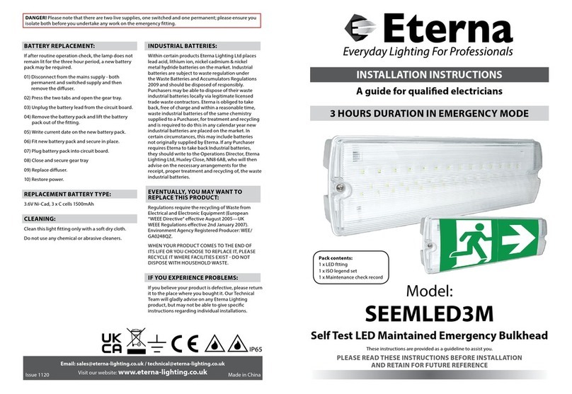
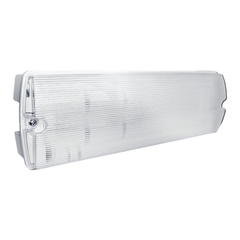
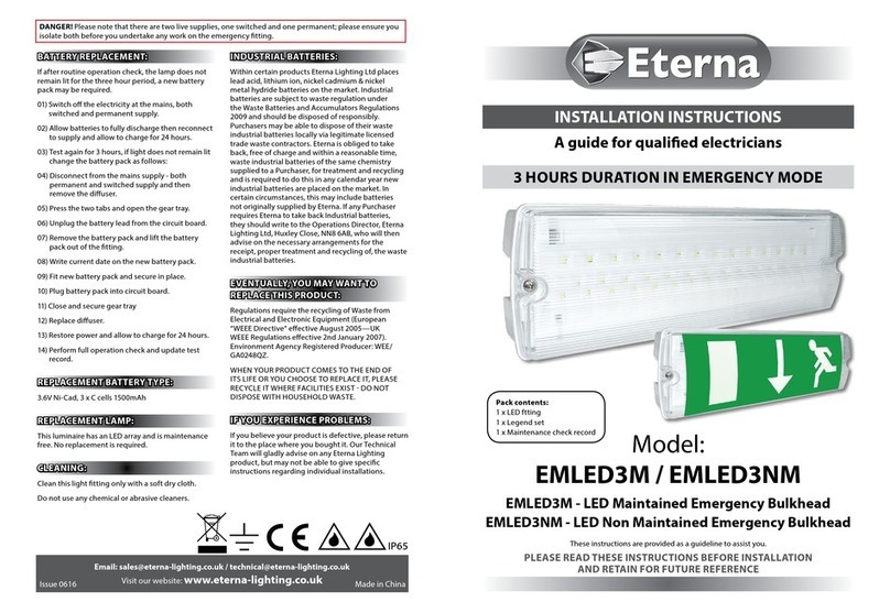
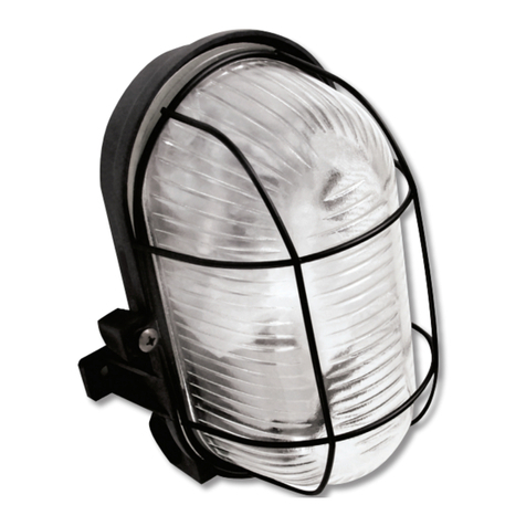
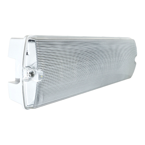
YD630M Maintained emergency bulkhead light 070809PA
Safetymarkings:IP65
Operation checks:
Periodictesting should be carried outmonthlyby
simulating afailure ofsupply, causing the fitting tobe
energised fromit’sbattery. Interruption ofthesupply
should be carried out by the operation of alocal keyswitch
or other isolation device.During thisperiod all fittings
should be examined visuallytoensure thattheyare
functioning correctly. Atthe end ofthe testperiod the
supplyshall berestoredand all indicatorlampsor devices
checked toensure thatthe normal supplyhasbeen
restored.
The duration of the simulated failure shall be:-
Eachmonth:
Isolatethe power supply and check the light isilluminated.
Thistestshould last for no more than 45 minutes.
Endorsethe test record form supplied.
Everysixmonths:
Isolatethe power supplyand checkthatthelightisstill
illuminated after 1hour. Endorsethe test record form.
Once eachyear:
Isolatethe power supplyand checkthatthelightisstill
illuminated after 3hours. Endorsethe test record form.
Importantnotes:
Pleasekeep thisinstruction bookletand testrecord in a
safeplace.Afire officeror other authorised person may
want tosee your record of inspection and testing.
The ballast and control gear must be operated onlywithin
the enclosure supplied.The gear must notbe operated
outside of the enclosure.
The batterycharging circuitandDCballastare separated
from the mainsby atleast basic (single layer )insulation.
When energised byaconstantmainssupply, the battery
will be constantlycharged whether or notthe lampis
illuminated.On failure ofthe constantmainssupply,the
fitting will switchautomaticallyusing transistorised
switching frombatterycharging tobatterydischarge
powering the lampwhether ornotthe lampwas
illuminated before the power failure.Boththe mainsand
batterysuppliesincorporatefuseprotection:see fittingfor
location and rating.
