manuals.online logo
Brands
  1. Home
  2. •
  3. Brands
  4. •
  5. Eterna
  6. •
  7. Lighting Equipment
  8. •
  9. Eterna SELMDDEM3 User manual

Eterna SELMDDEM3 User manual

Model:
SELMDDEM3
Self Test Recessed LED Emergency Drop Sign
These instructions are provided as a guideline to assist you.
PLEASE READ THESE INSTRUCTIONS BEFORE INSTALLATION
AND RETAIN FOR FUTURE REFERENCE
Pack contents:
1 x LED tting with up legend
1 x Maintenance check record
INSTALLATION INSTRUCTIONS
A guide for qualied electricians
3 HOURS DURATION IN EMERGENCY MODE
REPLACEMENT BATTERY TYPE:
3.6V 800mAh Ni-Cd batteries.
BATTERY REPLACEMENT:
If after routine operation check, the lamp does not
remain lit for the three hour period, a new battery
pack may be required.
01. Switch o the electricity at the mains.
02. Remove the diuser.
03. Remove the two screws indicated on the gear tray
and open the tting.
04. Disconnect the battery from the circuit board.
05. Cut the cable tie that secures the battery pack in
place and lift the battery pack out of the tting.
06. Write current date on the new battery pack.
07. Fit new battery pack securing in place using
cable tie.
08. Connect the battery to the circuit board.
09. Close and secure gear tray.
10. Replace diuser.
EVENTUALLY, YOU MAY WANT TO
REPLACE THIS PRODUCT:
Regulations require the recycling of Waste from
Electrical and Electronic Equipment (European “WEEE
Directive” eective August 2005—UK WEEE Regulations
eective 2nd January 2007). Environment Agency
Registered Producer: WEE/GA0248QZ.
WHEN YOUR PRODUCT COMES TO THE END OF ITS
LIFE OR YOU CHOOSE TO REPLACE IT, PLEASE RECYCLE
IT WHERE FACILITIES EXIST  DO NOT DISPOSE WITH
HOUSEHOLD WASTE.
INDUSTRIAL BATTERIES:
Within certain products Eterna Lighting Ltd places lead
acid, lithium ion, nickel cadmium & nickel metal hydride
batteries on the market. Industrial batteries are subject
to waste regulation under the Waste Batteries and
Accumulators Regulations 2009 and should be disposed
of responsibly. Purchasers may be able to dispose of
their waste industrial batteries locally via legitimate
licensed trade waste contractors. Eterna is obliged
to take back, free of charge and within a reasonable
time, waste industrial batteries of the same chemistry
supplied to a Purchaser, for treatment and recycling
and is required to do this in any calendar year new
industrial batteries are placed on the market. In certain
circumstances, this may include batteries not originally
supplied by Eterna. If any Purchaser requires Eterna
to take back Industrial batteries, they should write to
the Operations Director, Eterna Lighting Ltd, Huxley
Close, NN8 6AB, who will then advise on the necessary
arrangements for the receipt, proper treatment and
recycling of, the waste industrial batteries.
SPECIFICATIONS:
Self test in accordance with BS EN 62034 : 2012
Rated wattage: 3.5W
Viewing distance: 30m
IF YOU EXPERIENCE PROBLEMS:
If you believe your product is defective, please return it
to the place where you bought it. Our Technical Team
will gladly advise on any Eterna Lighting product, but
may not be able to give specic instructions regarding
individual installations.
Email: [email protected]o.uk / [email protected]o.uk
Visit our website: www.eterna-lighting.co.uk Made in ChinaIssue 1120
The light source contained in this luminaire
shall only be replaced by the manufacturer,
service agent or a similar qualied person.
CAUTION, RISK OF ELECTRIC SHOCK.
The light source is designed to last the lifetime of the
luminaire.
READ THIS FIRST:
Check the pack and make sure you have all of the
parts listed on the front of this booklet. If not,
contact the outlet where you bought this product.
This light tting must be installed by a competent
person in accordance with the Building Regulations
making reference to the current edition of the IEE
Wiring Regulations (BS7671).
As the buyer, installer and/or user of this product it
is your own responsibility to ensure that this tting
is t for the purpose for which you have intended
it. Eterna Lighting cannot accept any liability for
loss, damage or premature failure resulting from
inappropriate use.
This product is designed and constructed according
to the principles of the appropriate British Standard
and is intended for normal service. Use of this tting
in any other environment, for example in higher
than normal ambient temperatures, may result in a
foreshortened working life.
The batteries supplied with this tting are
consumable parts and therefore may be outside of
any warranty oered.
Switch o the mains before commencing installation
and remove the appropriate circuit fuse.
When working at heights, please use a suitable
platform.
Suitable for indoor use only.
This product is suitable for installation on surfaces
with normal ammability e.g. wood, plasterboard,
masonry. It is not suitable for use on highly
ammable surfaces (e.g. polystyrene, textiles).
This product is suitable for mounting in plasterboard
ceilings, suspended ceilings and similar board
surfaces. Check specication of ceiling for suitability.
Before making xing hole(s), check that there are no
obstructions hidden beneath the mounting surface
such as pipes or cables.
The chosen location of your new tting should allow
for the product to be securely mounted and safely
connected to the mains supply (lighting circuit).
Do not attach to surfaces which are damp or freshly
painted.
This product is designed for permanent connection
to xed wiring: this should be either a suitable
lighting circuit (protected with a 5 or 6 Amp MCB or
fuse) or a fused spur (with a 3 Amp fuse) via a fused
connection unit.
Make connections to the electrical supply in
accordance with the following code:
Live - Brown or Red, Neutral - Blue or Black
Earth - Green and Yellow
When making connections, ensure that the terminals
are tightened securely and that no strands of wire
protrude. Check that the terminals are tightened
onto the bared conductors and not onto any
insulation. Wrap loose terminal blocks well with
insulating tape.
This product must be connected to Earth.
You are advised at every stage of your installation to
double-check any electrical connections you have
made. After you have completed your installation
there are electrical tests that should be carried out:
these tests are specied in the Wiring Regulations
(BS7671) referred to in the Building Regulations.
IMPORTANT NOTES:
The control gear must be operated only within the
enclosure supplied. The gear must not be operated
outside of the enclosure.
The battery charging circuit and DC ballast are separated
from the mains by at least basic (single layer) insulation.
When energised by a constant mains supply, the battery
will be constantly charged whether or not the lamp is
illuminated. On failure of the constant mains supply,
the tting will switch automatically using transistorised
switching from battery charging to battery discharge
powering the lamp whether or not the lamp was
illuminated before the power failure. Both the mains and
battery supplies incorporate fuse protection: see tting
for location and rating.
CLEANING:
Clean this tting only with a soft dry cloth.
Do not use any chemical or abrasive cleaners.
INSTALLATION:
01. Undo the screws at each end of the diuser
or front plate and lift o.
02. Decide which of the cable entries you need to use
and remove one of the knock-outs if necessary.
03. Cut the hole in your mounting surface using the
dimensions, see Fig 1.
04. Oer the tting up through the hole in the ceiling and
allow to rest with the two large ears on the top side of
your ceiling, see Fig 2.
05. Undo the screws at each end of the gear tray and
allow to drop open.
06. Thread the mains supply cable in through the hole in
the back of the tting.
07. Make the electrical connections according to the
colour code opposite. Take care not to leave any
strands protruding from the terminals and to tighten
all terminals securely. Ensure also that the terminals
clamp onto the bare wire and not onto the insulation.
10. Mark the current date on the battery pack.
11. Connect the battery pack to the circuit board.
12. Close the gear tray and secure using the screws
removed earlier, see Fig 3.
13. Fit the sign panel into the slotted front plate:
A) Oer the top of the sign panel into the slot in the
diuser from beneath and press down on the top of
the diuser until it rests on the shoulders at the top
of the panel.
B) Fit the small split-pins into the holes at each end
of the top edge of the sign panel and bend the ends
over to stop them from coming out again, see Fig 3.
14. Replace the diuser or front plate and tighten
securely making sure that the tting is properly
located around the hole in your ceiling.
55mm
CEILING
CEILING
115mm
320mm
375mm
ø
15mm
Screw
Legend
Folded Pin Ends
Cover
Screw
Cover
Fitting
Fig 1
Fig 2
Fig 3
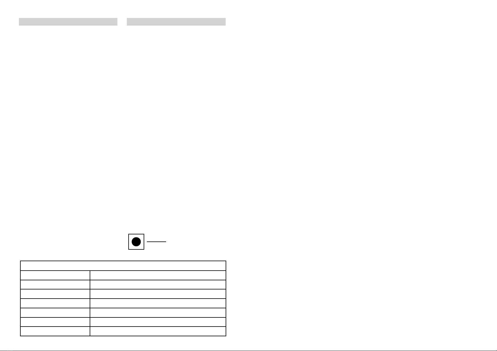
NOTE: Wires should be
stripped 13-14.5mm
for best t with the
push-t terminal block.
13-14.5mm
Wire
DANGER!
NOTE: this unit has a permanent live mains supply,
please ensure you isolate before removing cover.
There may also be a seperate switched supply that
controls the emergency light tting - this also needs
to be isolated.
NOTE: please keep this instruction booklet and
the test record in a safe place. A re ocer or
other authorised person may want to see your
record of inspection and testing.
OPERATION CHECKS:
This product is tted with an automatic, self-test
function that will commission and test itself in
accordance with the requirements of the British
Standards. Monthly and annual tests will be
automatically completed as detailed below with
tests including battery charge condition, functional
test and duration test.
Monthly – ten minute functional test
Annually – full three-hour duration test
• On installation a date will be randomly assigned for
the rst monthly and rst annual test.
• The initial monthly test will be between 16 and 30
days from installation.
• The initial full-duration test will be between 200
and 360 days from installation (annual tests will
then be conducted every 360 days).
• The schedule of these tests will be remembered
for a period of 7 days if no power is supplied to the
luminaire.
• If there is a mains failure in 24 hours before a test
is due to be conducted, the test will automatically
be postponed until sucient time is allowed to
recharge the battery.
• If there is a mains failure during the self-test
operation the unit will go into emergency mode.
TESTING
This product is designed to conduct self-testing in
accordance with EN 62034, the results of monthly
and annual tests should be endorsed on the test
record form supplied.
Because of the possibility of a failure of the normal
lighting supply occurring shortly after a period of
testing of the emergency lighting system or during
the subsequent recharge period, all full duration
tests shall wherever possible be undertaken
preceding time of low risk to allow for battery
recharge.
Daily:
Visual inspection of the battery charge LED.
Each Month:
The product will be energised from its battery for
adequate time to ensure that emergency mode is
functioning correctly.
Once Each Year:
The product will be placed into emergency mode
and check that the duration provided meets the
specied time period.
There is a control button within the tting:
• Press for 1 second to reset the timer function, the
monthly test will then be conducted after 30 days
and the annual test after 360 days.
• Press for 3 seconds to initiate a 5 minute functional
test.
NOTE: This can only be completed under mains
conditions and accordingly must only be conducted
by a qualied electrician.
PERFORMANCE AND FAULT INDICATORS:
Normal operation constant green LED
Duration test underway red indicator ashing rapidly
Battery circuit failure red indicator ashing once every 3 seconds
Light source failure red indicator ashing twice every 3 seconds
Failure of duration test red indicator ashing three times every 3 seconds
Auto test function fails red indicator ashing four times every 3 seconds
LED indicator o in emergency mode (mains failure)
SW1
Month
Test
Year: Year: Year: Year: Year:
Sign Date Sign Date Sign Date Sign Date Sign Date
01 Function
02 Function
03 Function
04 Function
05 Function
06 Function
07 Function
08 Function
09 Function
10 Function
11 Function
12 Function
INSTALLATION, MAINTENANCE
AND OPERATION CHECK RECORD
Product
Code:
Self Test Product
Description:
Product
Location:
Installation
Date:
Installed
By:

Other Eterna Lighting Equipment manuals

Eterna TUS6NL User manual

Eterna

Eterna TUS6NL User manual

Eterna PERLED20 User manual

Eterna

Eterna PERLED20 User manual

Eterna PLDGEM3 User manual

Eterna

Eterna PLDGEM3 User manual

Eterna D040 Setup guide

Eterna

Eterna D040 Setup guide

Eterna ELEGAN5EM3 User manual

Eterna

Eterna ELEGAN5EM3 User manual

Eterna VECOEM3M User manual

Eterna

Eterna VECOEM3M User manual

Eterna MSCSLEDCR User manual

Eterna

Eterna MSCSLEDCR User manual

Eterna LDLEM3 User manual

Eterna

Eterna LDLEM3 User manual

Eterna VECOMEM3 User manual

Eterna

Eterna VECOMEM3 User manual

Eterna SEMEM3 User manual

Eterna

Eterna SEMEM3 User manual

Eterna YD630M Setup guide

Eterna

Eterna YD630M Setup guide

Eterna SELDLEM3 User manual

Eterna

Eterna SELDLEM3 User manual

Eterna SAP70MINI User manual

Eterna

Eterna SAP70MINI User manual

Eterna RDL12 User manual

Eterna

Eterna RDL12 User manual

Eterna EXITBOXM Series Setup guide

Eterna

Eterna EXITBOXM Series Setup guide

Eterna SL1WH Setup guide

Eterna

Eterna SL1WH Setup guide

Eterna SFLWW9 Setup guide

Eterna

Eterna SFLWW9 Setup guide

Eterna D087 Setup guide

Eterna

Eterna D087 Setup guide

Eterna ML5040 User manual

Eterna

Eterna ML5040 User manual

Eterna LEDREM3 User manual

Eterna

Eterna LEDREM3 User manual

Eterna EAC158EM3 Setup guide

Eterna

Eterna EAC158EM3 Setup guide

Eterna SEEMLED3M User manual

Eterna

Eterna SEEMLED3M User manual

Eterna LED4WH Setup guide

Eterna

Eterna LED4WH Setup guide

Eterna SQPRISMW User manual

Eterna

Eterna SQPRISMW User manual

Popular Lighting Equipment manuals by other brands

Wetelux 84 54 33 instruction manual

Wetelux

Wetelux 84 54 33 instruction manual

Sensio Dart/Primo 2 quick start guide

Sensio

Sensio Dart/Primo 2 quick start guide

EuroLite Superstrobe 2700 user manual

EuroLite

EuroLite Superstrobe 2700 user manual

ROGUE FlashBender 2 quick start guide

ROGUE

ROGUE FlashBender 2 quick start guide

Lightolier Lightolier SORA-5 Product guide

Lightolier

Lightolier Lightolier SORA-5 Product guide

Robus HARBOUR RHA10402FTV2-24 instructions

Robus

Robus HARBOUR RHA10402FTV2-24 instructions

Zodiac Chlor Expert Instructions for installation and use

Zodiac

Zodiac Chlor Expert Instructions for installation and use

Exo Terra PT2335 operating instructions

Exo Terra

Exo Terra PT2335 operating instructions

Mobiclinic GROWFLEX X2 instruction manual

Mobiclinic

Mobiclinic GROWFLEX X2 instruction manual

Rollei Lumen Panel 600Bi manual

Rollei

Rollei Lumen Panel 600Bi manual

EuroLite Pinspot PAR36 user manual

EuroLite

EuroLite Pinspot PAR36 user manual

American DJ SS-DMX/MATRIX Operation manual

American DJ

American DJ SS-DMX/MATRIX Operation manual

CARLO GAVAZZI Sense SC2 quick start guide

CARLO GAVAZZI

CARLO GAVAZZI Sense SC2 quick start guide

Poolguard PGRM-2 Operating instructions manual

Poolguard

Poolguard PGRM-2 Operating instructions manual

Arpella LEDWSM2430 installation instructions

Arpella

Arpella LEDWSM2430 installation instructions

Robe Color Sport 1200 Profile user manual

Robe

Robe Color Sport 1200 Profile user manual

Neske Multicolor 2 user manual

Neske

Neske Multicolor 2 user manual

Startax AUTOLINE 1606-40108 manual

Startax

Startax AUTOLINE 1606-40108 manual

manuals.online logo
manuals.online logoBrands
  • About & Mission
  • Contact us
  • Privacy Policy
  • Terms and Conditions

Copyright 2025 Manuals.Online. All Rights Reserved.