Evelo Aries User manual
Owner’s Manual
Important Safety and Product Information
eVelO.COM

2
eVelO.COM
3
eVelO.COM
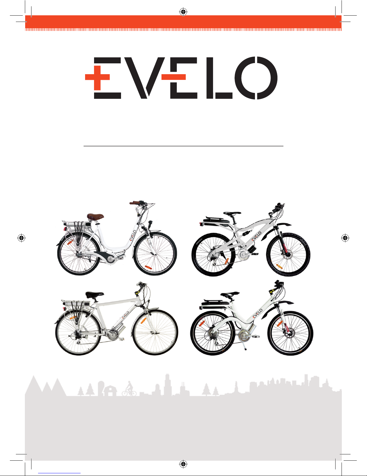
Congratulations on the purchase of your new, power-
assisted electric bike from EVELO Electric Bicycles!
This manual is designed to give you an understanding of the basic operation and
maintenance of this bike. We believe that great customer service is part of your purchase,
so please reach out to us if you ever need guidance or assistance.
The latest version of this Owner’s Manual is always available at
http://www.EVELO.com/ownersmanual.pdf. We suggest that you read this manual in its
entirety before using your bicycle.
Riding a bicycle is an inherently dangerous activity, and it is your responsibility to ride
safely and within your abilities. Proper assembly is vital to the safe operation of your
bicycle, so seek professional assistance if you are unable to complete the assembly of
your bicycle as outlined in this manual.
Our bicycles have been tested and recommended for use by riders weighing 250 pounds
(113 kilograms) or less.
welCOMe!
Your enjoyment of — and satisfaction with — your new bike is important to us. For after-
support at 1-877-991-7272.
TaBle OF COnTenTs
COnTaCT InFOrMaTIOn
Welcome!
Contact Information
Registration
Warranty
Battery Care and Maintenance
Assembly
Aries
Aurora
Luna
Orion
Riding Your EVELO Electric Bicycle
Maintenance
Troubleshooting
3
3
4
4
8
10
11
18
25
32
39
45
46

4
eVelO.COM
5
eVelO.COM
Please ll out the warranty form located on our website at
http://www.evelo.com/warranty-and-returns/registration/ to register your bicycle.
Registration is required before we can process a warranty claim. Registration is also a
great security feature. Each bike has two unique serial numbers — one for the frame and
the other for the motor — which the authorities can use to identify your bike if it is stolen.
The frame’s serial number is located on the head tube, just above the front fork. The
motor’s serial number is on the top of the motor housing.
The battery lock key number is stamped on the key itself, and may be useful if
replacement is required.
Please take a moment to write your serial numbers here and keep a record in a safe place:
Motor Serial NuMber: ................................................................
FraMe Serial NuMber: ................................................................
battery Key NuMber: ................................................................
reGIsTerInG YOur
new eleCTrIC BICYCle
Warranty Overview
Every EVELO Electric Bicycle comes with an 18-month warranty against manufacturing
defects in materials or workmanship on its frame, battery, controller, and motor assembly.
This warranty applies only to the original registered owner of the EVELO bicycle and is not
transferable. This limited warranty does not apply to normal wear and tear, malfunctions,
warranTY
or failures due to abuse, neglect, improper repair, improper maintenance, alteration,
modication, accidents, or other improper use.
It is important that you register your new bicycle within 30 days after purchase in order to
activate the warranty.
Terms of the Warranty
For your reference, we’ve outlined the comprehensive terms of the warranty below:
Frame, Battery, Controller, and Motor Assembly — are warranted to be free from•
defects in material or workmanship for a period of eighteen (18) months from
purchase. After any warranty period has elapsed, you may purchase spare and
replacement parts by contacting us.
Replacement Batteries (if provided) — are warranted to be free from defects in•
material or workmanship for a period of six (6) months from purchase.
Other Components — are warranted by the individual manufacturers.•
Please note that while every effort is made to provide our customers with a superb
shopping experience, issues sometimes can arise during shipping. If any parts of your
bicycle have been damaged during shipping, EVELO will send a replacement part at our
expense and will work with you or the bike shop of your choice to x the issue at no cost
to you.
For warranty issues, EVELO will cover the cost of labor involved in handling the warranty
service within a 30-day period after purchase. To receive this service, the customer needs
to bring the bike to the authorized EVELO Full Service Dealer from which the bike was
purchased. If the bicycle was purchased on the website, EVELO will help to arrange an
appointment at a bike shop near the customer to investigate and resolve the issue. If a
part or component is faulty, please contact us by email and provide a video or photo of
the faulty part.
After the 30-day free labor period for repairs, the customer will be responsible for labor
costs associated with warranty replacements.
For any parts under warranty that need to be replaced within the 18-month time frame,
EVELO will cover the cost of freight to the customer.

6
eVelO.COM
7
eVelO.COM
Limited Remedy: Unless otherwise provided, the sole remedy under the above warranty, or
any implied warranty, is limited to the replacement of defective components and parts with
those of equal or greater value at the sole discretion of EVELO. Unless this falls within the
30-day free labor repair period, the customer is responsible for labor costs associated with
warranty replacements.
In no event shall EVELO be responsible for direct, incidental or consequential damages,
including, without limitation, damages for personal injury, property damage, or economic
losses, whether based on contract, warranty, negligence, product liability, or any other
theory. Some states do not allow the exclusion or limitation of damages, so the above
limitation or exclusion may not apply to you.
Exclusions: The above warranty, or any implied warranty, does not cover normal wear and
tear. All warranties are void if the electric vehicle is used for other than normal activities,
including, but not limited to, failing to follow the owner’s manual or using the electric
vehicle for commercial activities or in competitive events, and training for such activities or
events.
EVELO makes no other warranties, express or implied. All implied warranties, including the
warranties of merchantability and fitness for a particular purpose, are limited in duration to
that of the express warranties stated above. Some states do not allow limitations on how
long an implied warranty lasts, so the above limitation may not apply to you. This warranty
gives you specific legal rights, and you may also have other rights which vary from state to
state.
8
eVelO.COM
9
eVelO.COM
The battery provided with your EVELO Electric Bicycle is a high-quality unit that requires
very little from the user in terms of care. However, a few things are worth noting with
respect to any Lithium Ion battery. To maximize the lifespan of your battery, we
suggest an initial conditioning charge of 12 hours. After that, connect it to the charger
as needed. While there is no need to recharge the battery following short trips, we
recommend not leaving a battery partially discharged — and especially not completely
discharged — for extended periods of time.
A typical charge takes 4-6 hours (longer in very cold temperatures) to complete. The
battery will perform best if you do NOT leave it plugged in constantly, since charging /
discharging keeps the electrons in the unit moving, which improves longevity.
Using Your Charger
The charger that comes with your bike has internal controls that prevent overcharging of
the battery. First, plug the charger into the battery. Then check the wire connections at the
charger block to make sure the cord is fully seated, and then plug it into a 120v AC outlet.
The light on the charger should be RED, and that light will change to GREEN when the
battery is fully charged. We do not recommend leaving the unit plugged in for extended
periods of time.
In addition, we do not recommend using the charger unit in poorly ventilated spaces such
as closets or drawers, as it may overheat.
Environmental Conditions
Temperature extremes can affect your battery. Please keep it within the following
temperature ranges, as suggested by the battery manufacturer:
Charging: 32 degrees to 113 degrees F (0 degrees – 45 degrees C)
Discharging and Storage: -4 degrees to 140 degrees F (-20 degrees to 60 degrees C)
Storage
If you store your battery for 30 days or longer, it is suggested that you keep it in a place
that is within the above temperatures and give it a full 12-hour conditioning charge every
30 days.
BaTTerY Care & MaInTenanCe

10
eVelO.COM
11
eVelO.COM
Overview
The models in our line are very similar, but do have some
differences — especially when it comes to assembly.
NOTE : If you do not have the ability or skill to assemble the
bicycle yourself, please take it to a local bike shop for professional
assembly.
You should have received an email containing an assembly video after
you placed your order. Contact us if you would like that video re-sent.
In addition, our Customer Service Team can help guide you through the
process if needed. Tools to complete the job are included, and some of
the smaller pieces are packed inside the charger box to prevent loss.
Proper assembly is extremely important for the safe and smooth
operation of your electric bicycle. Please read through the entire
assembly instructions before beginning.
Once again, if you do not feel comfortable assembling the bicycle
yourself, please take it to a qualified bicycle mechanic.
The following are assembly directions for each of the four EVELO models.
Find and follow the specic directions for the model of electric bicycle
you have purchased.
asseMBlY
OF YOur eVelO eleCTrIC BICYCle
arIes
MODel
12
arIes MODel
13
arIes MODel
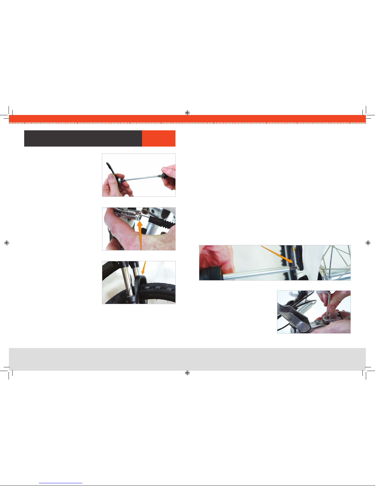
STEP 1 :INSTALL FRONT WHEEL
The front wheel is attached to the bike with a quick-release type of skewer. After1.
locating the skewer, remove the nut on the end opposite the lever, and slide one of
the conical springs onto the skewer — wide-end rst.
Once the spring is against the lever’s nut, slide the skewer through the axle so that2.
the lever is on the same side as the brake disc.
Now slide the second spring onto the skewer — narrow-end rst — then screw the3.
nut partially back on.
Place the wheel into the fork, taking care to make sure the disc goes into the brake4.
caliper.
With the axle fully seated into the fork dropouts (the slots that accept the axle), and5.
the lever in the oPeN position, turn the nut to adjust the clamping pressure, and
swing the lever rearward to the CloSeD position, where you will feel noticeable
resistance. The lever should leave a slight impression in your hand, and the lever
should be parallel to the center-line of the bike when adjusted properly.
CRITICAL :If the wheel is oriented correctly, the brake arch (the painted portion of
the fork that bridges the two fork legs) of the front fork should be rotated FORWARD,
as in the photo.
You can now lower the kickstand to keep the bike upright for the remainder of the
assembly.
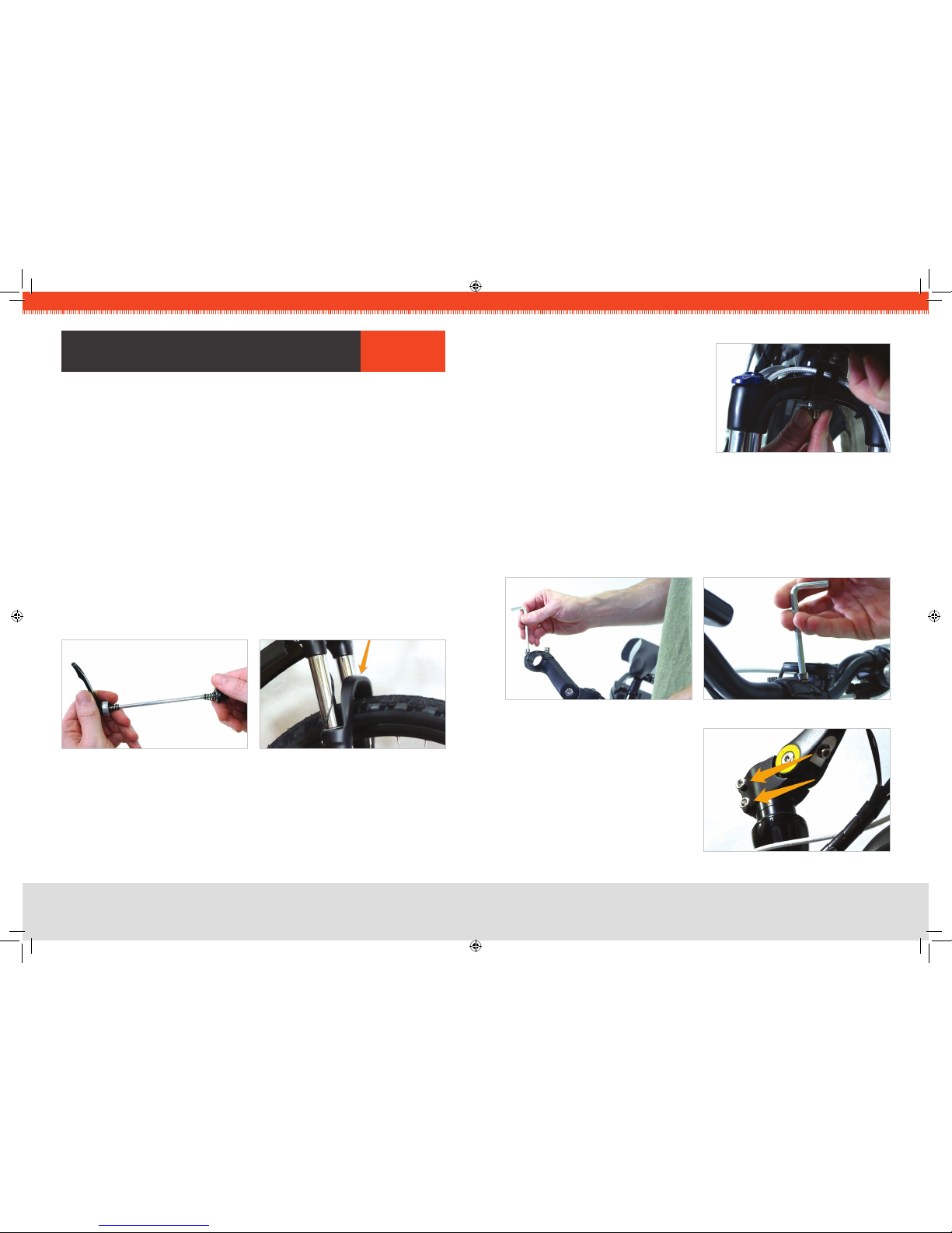
FIG 1A. QUICK RELEASE SKEWER FIG 1B. BRAKE ARCH
asseMBlY arIes STEP 2 :ATTACH FRONT FENDER
Locate the special threaded nut on the1.
underside of the fork that has been
installed at the factory.
Using the wrench and bolt provided,2.
install the fender from the underside of
the fork.
FIG 2. FENDER BOLT
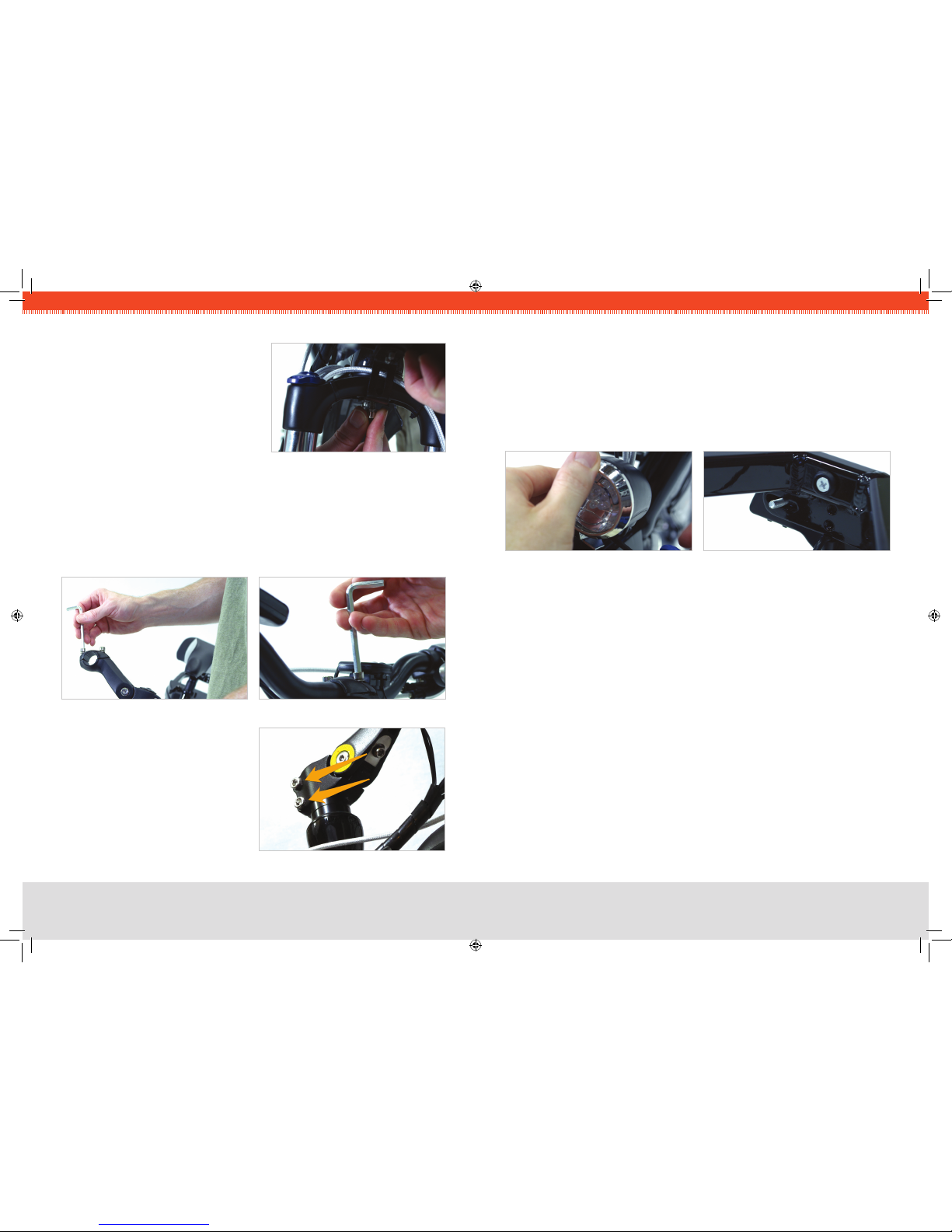
STEP 3 :ATTACH HANDLEBARS
Remove the two bolts that hold the handlebar clamping bracket on.1.
While taking care to keep the wires and cables as straight as possible, place the center2.
of the handlebars into the bracket and replace the upper portion of the bracket.
Tighten the bolts evenly so there is equal space at the front and rear of the bracket.3.
Firmly tighten both of the bolts.
FIG 4. BARS IN CLAMPING BRACKETFIG 3. CLAMPING BRACKET
FIG 5. STEM CLAMP BOLTS
Loosen the two bolts that clamp the4.
handlebar stem to the steer tube, and
align the handlebars with the front
wheel.
Firmly re-tighten the two bolts.5.
Note: Do not loosen the bolt located in
the top-center of the metal cap.

14
arIes MODel
15
arIes MODel
STEP 4 :INSTALL HEADLIGHT
Attach the headlight to the front fender bracket, taking care to run the wires as cleanly1.
as possible.
Remove the single bolt from the light, keeping the nut in place.2.
Install the light on the bracket located on the front fender, insert the bolt, and tighten3.
securely.
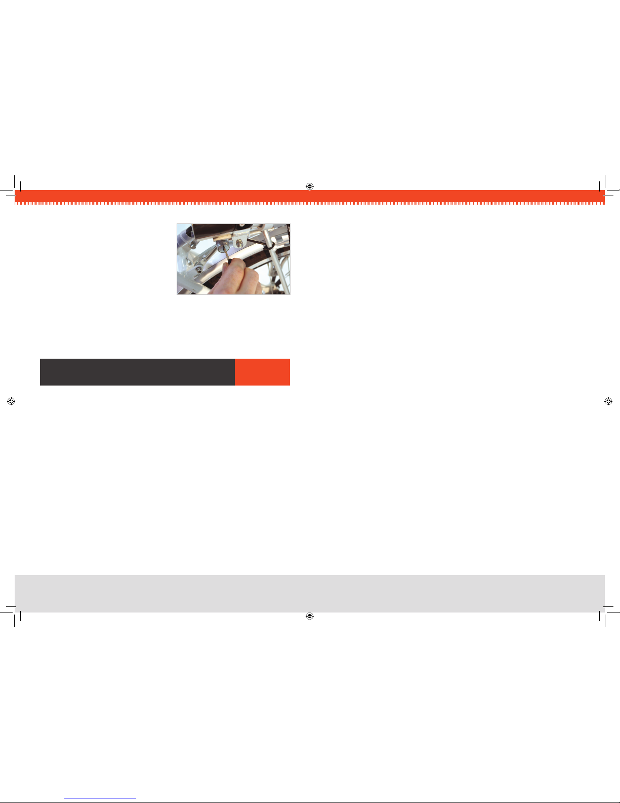
STEP 5 :INSTALL TAIL LIGHT
Remove the nuts and washers from the light, and install the bolt studs through the1.
bracket at the rear of the bicycle.
Make sure the wire is not caught between the light and the bracket. Instead, route2.
the wire over the bottom portion of the tail light bracket. Install the at washer, the
split washer, and the nut (in that order) onto each bolt, and tighten with the wrench
provided. Do not over-tighten.
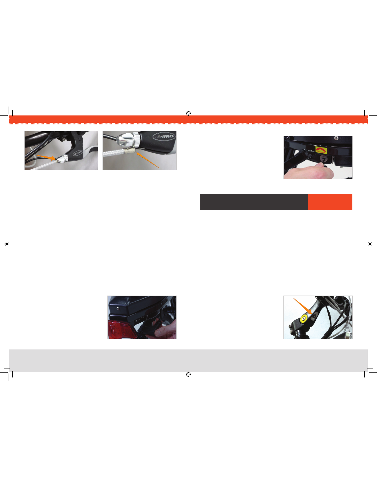
STEP 6 :CHECK BRAKE INSTALLATION
Follow each brake cable, starting at the brake lever. Make sure that the brake housing1.
(the sheathing that the cable runs through) is fully seated into the cylindrical hole at
the brake lever, as shown in Fig. 8 on the next page.
Fig. 9 shows a dislodged housing, which occasionally occurs during shipping and
handling.
Check the housing at the brake caliper end as well — it also should be seated into2.
the hole in the brake.
Repeat for the other brake.3.
FIG 6. HEADLIGHT ATTACHMENT FIG 7. TAIL LIGHT BRACKET
STEP 7 :INSTALL PEDALS
Keep in mind that the left and right pedals are threaded differently, and it is crucial that
they are installed on the correct side of the bicycle. For this reason, they are marked “L”
and “R” with stickers at the factory.
Locate the right-side pedal (marked with an “R”).1.
Thread the “R” pedal clockwise onto the drive-side crank (side of the bike with gears).2.
Tighten the “R” pedal clockwise with a 15 mm wrench or the wrench provided.3.
Locate the left-side pedal (marked with an “L”).4.
Thread the “L” pedal5. CouNter-CloCKWiSe*onto the non-drive-side crank (side of
the bike without gears).
Tighten the “L” pedal6. CouNter-CloCKWiSe with a 15 mm wrench or the wrench
provided.
*NOTE :The left and right pedals are not interchangeable.
The left (“L”) pedal and crank are reVerSe-tHreaDeD so that the pedal will not come
loose while riding. To tiGHteN the left pedal, turn CouNter-CloCKWiSe.
To looSeN it, turn CloCKWiSe.
STEP 8 :INSTALL & CONNECT BATTERY
Once the battery has been fully1.
charged (see section “Battery Care and
Maintenance” on Page 8), simply lower it
straight down into the frame. Fully push
the large, three-pronged plug on the
right side of the bicycle into the socket
in the battery.
FIG 10. BATTERY SOCKET
FIG 8. CORRECT BRAKE HOUSING FIG 9. INCORRECT HOUSING
16
arIes MODel
17
arIes MODel
Using your key, lock the battery — this2.
will help stabilize it when riding and also
provide some anti-theft security. The lock
is located on the left side of the battery
case.
FIG 11. KEY LOCK
FIT aDJusTMenTs arIes
Many parts of your new EVELO Electric Bicycle can be
customized for a personalized t.
Seat Adjustment
The seat is easily adjusted up or down by ipping the quick-release lever that clamps
the post into the bike. Note that there is a “minimum insertion line” stamped on the seat
post that must be adhered to for safety’s sake. (If you need your seat to be higher than
permitted with the stock seat post, please contact us.)
The seat can also be moved forward and backward by loosening the single bolt on the
underside of the seat. Since it slides on its rails, there is no need to remove the bolt — just
loosen it, adjust, and rmly re-tighten. Loosening this bolt also lets you change the angle
of the seat up or down a bit. Again, be sure to re-tighten it rmly if you loosen it to change
the seat position in any way.
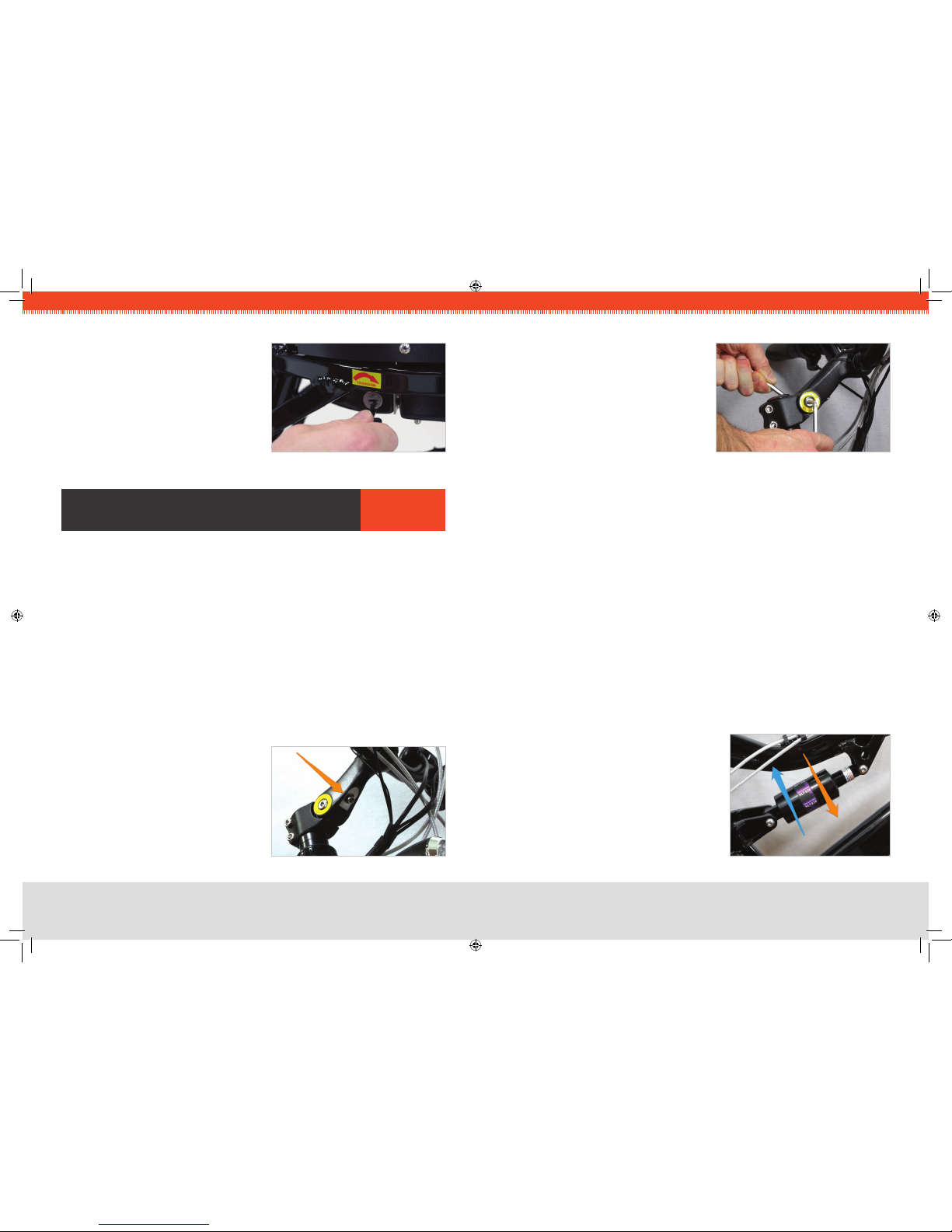
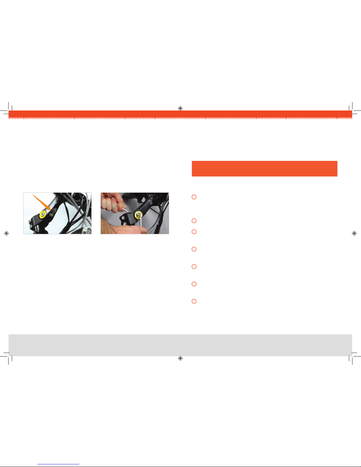
Stem Adjustment
To adjust the handlebars to a customized height:
Loosen the bolt indicated by the arrow in1.
Fig. 12. Access this bolt from underneath
the handlebars.
FIG 12. STEM CLAMP BOLT
Next, slightly loosen the bolts on either side.2.
Once you have loosened all three bolts,3.
move the stem to the desired height.
Re-tighten the two side bolts rst, ensuring4.
they are tightened very well.
Finish by re-tightening the rst bolt located5.
under the handlebars (the one indicated by
the arrow in Fig. 12).
Depending on how much you moved the stem, you may want to rotate the6.
handlebars themselves, especially if you need to correct the angle of the brake levers.
Just loosen the two bolts that clamp the handlebar, rotate it to the desired position,
and re-tighten the bolts. (This is described in the section, “Attach Handlebars” on
Page 13.)
Double-check all bolts to make sure they are tight.7.
Front Shock
Please consult the manual provided by the manufacturer.
Rear Shock
To make the ride rmer and lower the frame slightly, grasp the barrel of the shock and
rotate in the direction of the Orange arrow (shown in Fig. 14) to compress the internal
spring. Alternatively, rotate in the direction of the Blue arrow to relax the spring, which will
increase the “travel” of the shock and soften the ride, raising the frame slightly.
Tire Inflation
The tires have a range of recommended ination
of 40-65 psi. This range is also indicated on
the sidewall of the tire. Lower pressure will give
a softer ride. A higher pressure will provide
a rmer ride, but will give the best range per
charge.
FIG 13. TWO OPPOSING BOLTS
FIG 14. REAR SHOCK ADJUST

18
aurOra MODel
19
aurOra MODel
STEP 1 :INSTALL FRONT WHEEL
The front wheel is attached to the bike with a quick-release type of skewer. After1.
locating the skewer, remove the nut on the end opposite the lever, and slide one of
the conical springs onto the skewer — wide-end rst.
Once the spring is against the lever’s nut, slide the skewer through the axle so that2.
the lever is on the same side as the brake disc.
Now slide the second spring onto the skewer — narrow-end rst — then screw the3.
nut partially back on.
Place the wheel into the fork, taking care to make sure the disc goes into the brake4.
caliper.
With the axle fully seated into the fork dropouts (the slots that accept the axle), and5.
the lever in the oPeN position, turn the nut to adjust the clamping pressure, and
swing the lever rearward to the CloSeD position, where you will feel noticeable
resistance. The lever should leave a slight impression in your hand, and the lever
should be parallel to the center-line of the bike when adjusted properly.
CRITICAL :If the wheel is oriented correctly, the brake arch (the painted portion of
the fork that bridges the two fork legs) of the front fork should be rotated FORWARD,
as in the photo.
You can now lower the kickstand to keep the bike upright for the remainder of the
assembly.
FIG 1A. QUICK RELEASE SKEWER FIG 1B. BRAKE ARCH
asseMBlY aurOra
aurOra
MODel
20
aurOra MODel
21
aurOra MODel
STEP 2 :ATTACH FRONT FENDER
Locate the special threaded nut on the1.
underside of the fork that has been
installed at the factory.
Using the wrench and bolt provided,2.
install the fender from the underside of
the fork.
FIG 2. FENDER BOLT
STEP 3 :ATTACH HANDLEBARS
Remove the two bolts that hold the handlebar clamping bracket on.1.
While taking care to keep the wires and cables as straight as possible, place the center2.
of the handlebars into the bracket and replace the upper portion of the bracket.
Tighten the bolts evenly so there is equal space at the front and rear of the bracket.3.
Firmly tighten both of the bolts.
FIG 4. BARS IN CLAMPING BRACKETFIG 3. CLAMPING BRACKET
STEP 4 :INSTALL HEADLIGHT
Attach the headlight to the front fender bracket, taking care to run the wires as cleanly1.
as possible.
Remove the single bolt from the light, keeping the nut in place.2.
Install the light on the bracket located on the front fender, insert the bolt, and tighten3.
securely.
STEP 5 :INSTALL TAIL LIGHT
Remove the nuts and washers from the light, and install the bolt studs through the1.
bracket at the rear of the bicycle.
Make sure the wire is not caught between the light and the bracket. Instead, route2.
the wire over the bottom portion of the tail light bracket. Install the at washer, the
split washer, and the nut (in that order) onto each bolt, and tighten with the wrench
provided. Do not over-tighten.
STEP 6 :CHECK BRAKE INSTALLATION
Follow each brake cable, starting at the brake lever. Make sure that the brake housing1.
(the sheathing that the cable runs through) is fully seated into the cylindrical hole at
the brake lever, as shown in Fig. 8 on Page 22.
Fig. 9 shows a dislodged housing, which occasionally occurs during shipping and
handling.
Check the housing at the brake caliper end as well — it also should be seated into2.
the hole in the brake.
Repeat for the other brake.3.
FIG 6. HEADLIGHT ATTACHMENT FIG 7. TAIL LIGHT BRACKET
FIG 5. STEM CLAMP BOLTS
Loosen the two bolts that clamp the4.
handlebar stem to the steer tube, and
align the handlebars with the front
wheel.
Firmly re-tighten the two bolts. Note:5.
Do not loosen the bolt located in the
top-center of the metal cap.
22
aurOra MODel
23
aurOra MODel
STEP 7 :INSTALL PEDALS
Keep in mind that the left and right pedals are threaded differently, and it is crucial that
they are installed on the correct side of the bicycle. For this reason, they are marked “L”
and “R” with stickers at the factory.
Locate the right-side pedal (marked with an “R”).1.
Thread the “R” pedal clockwise onto the drive-side crank (side of the bike with gears).2.
Tighten the “R” pedal clockwise with a 15 mm wrench or the wrench provided.3.
Locate the left-side pedal (marked with an “L”).4.
Thread the “L” pedal5. CouNter-CloCKWiSe*onto the non-drive-side crank (side of
the bike without gears).
Tighten the “L” pedal6. CouNter-CloCKWiSe with a 15 mm wrench or the wrench
provided.
*NOTE :The left and right pedals are not interchangeable.
The left (“L”) pedal and crank are reVerSe-tHreaDeD so that the pedal will not come
loose while riding. To tiGHteN the left pedal, turn CouNter-CloCKWiSe.
To looSeN it, turn CloCKWiSe.
STEP 8 :INSTALL & CONNECT BATTERY
Once the battery has been fully1.
charged (see section “Battery Care and
Maintenance” on Page 8), simply lower it
straight down into the frame. Fully push
the large, three-pronged plug on the
right side of the bicycle into the socket
in the battery.
FIG 10. BATTERY SOCKET
FIG 8. CORRECT BRAKE HOUSING FIG 9. INCORRECT HOUSING
Using your key, lock the battery — this2.
will help stabilize it when riding and also
provide some anti-theft security. The lock
is located on the left side of the battery
case.
FIG 11. KEY LOCK
FIT aDJusTMenTs aurOra
Many parts of your new EVELO Electric Bicycle can be
customized for a personalized t.
Seat Adjustment
The seat is easily adjusted up or down by ipping the quick-release lever that clamps
the post into the bike. Note that there is a “minimum insertion line” stamped on the seat
post that must be adhered to for safety’s sake. (If you need your seat to be higher than
permitted with the stock seat post, please contact us.)
The seat can also be moved forward and backward by loosening the single bolt on the
underside of the seat. Since it slides on its rails, there is no need to remove the bolt — just
loosen it, adjust, and rmly re-tighten. Loosening this bolt also lets you change the angle
of the seat up or down a bit. Again, be sure to re-tighten it rmly if you loosen it to change
the seat position in any way.
Stem Adjustment
To adjust the handlebars to a customized height:
Loosen the bolt indicated by the arrow in1.
Fig. 12. Access this bolt from underneath
the handlebars.
FIG 12. STEM CLAMP BOLT

24
aurOra MODel
25
aurOra MODel
Next, slightly loosen the bolts on either side.2.
Once you have loosened all three bolts,3.
move the stem to the desired height.
Re-tighten the two side bolts rst, ensuring4.
they are tightened very well.
Finish by re-tightening the rst bolt located5.
under the handlebars (the one indicated by
the arrow in Fig. 12).
Depending on how much you moved the stem, you may want to rotate the6.
handlebars themselves, especially if you need to correct the angle of the brake levers.
Just loosen the two bolts that clamp the handlebar, rotate it to the desired position,
and re-tighten the bolts. (This is described in the section, “Attach Handlebars” on
Page 20.)
Double-check all bolts to make sure they are tight.7.
Front Shock
Please consult the manual provided by the manufacturer.
Tire Inflation
The tires have a range of recommended ination of 40-65 psi. This range is also indicated
on the sidewall of the tire. Lower pressure will give a softer ride. A higher pressure will
provide a rmer ride, but will give the best range per charge.
FIG 13. TWO OPPOSING BOLTS
luna
MODel
26
luna MODel
27
luna MODel
STEP 1 :INSTALL FRONT WHEEL
To install the front wheel, you rst need1.
to determine the right and left sides
of the front wheel. The easiest way
to accomplish this is to nd the small
magnet located on one of the spokes,
and orient the wheel so that the magnet
is on the same side as the black sensor
attached to the fork. This will ensure you
have correctly oriented the wheel as to
left and right.
The front wheel is attached to the bike2.
with a quick-release type of skewer. After
locating the skewer, remove the nut on
the end opposite the lever, and slide one
of the conical springs onto the skewer —
wide-end rst.
Once the spring is against the lever’s nut,3.
slide the skewer through the axle so that
the lever is on the left side of the wheel.
Now slide the second spring onto the4.
skewer — narrow-end rst — then screw
the nut partially back on.
Rotate the fork so the brake is toward the5.
front of the bike.
Release the front brake by squeezing the6.
brake arms, and lift the bent tube holding
the cable out of its cradle (indicated by the
arrow in Fig. 1B).
With the axle fully seated into the fork dropouts (the slots that accept the axle), and the7.
lever in the oPeN position, turn the nut to adjust the clamping pressure, and swing the
lever rearward to the CloSeD position, where you will feel noticeable resistance.
The lever should leave a slight impression in your hand, and the lever should be parallel to
the center-line of the bike when adjusted properly.
FIG 1C. BRAKE ARCH
asseMBlY luna
FIG 1A. QUICK RELEASE SKEWER
STEP 2 :ATTACH FRONT FENDER & HEADLIGHT
Loosen and remove the pre-attached bolt that goes through the brake arch.1.
Slide the fender into position, placing the silver tab that extends upward in front of the2.
brake arch.
Re-insert the bolt from the backside.3.
Bring the headlight into position in front of the brake arch, and screw the bolt into it.4.
Tighten the bolt.5.
Remove the two Phillips screws near the front axle. Bring the black plastic tabs on6.
the end of the wire struts up and bolt them in place using the screws. Repeat for each
side.
STEP 3 :ATTACH HANDLEBARS
Lift the handlebar assembly up. After1.
sliding the black switch upward to
release the lock, lift the clamp lever to
reveal a silver Allen (hex) bolt. Loosen
that bolt slightly.
CRITICAL :If the wheel is oriented correctly, the brake arch (the painted portion
of the fork that bridges the two fork legs) of the front fork should be rotated
FORWARD, as in Fig 1C.
You can now lower the kickstand to keep the bike upright for the remainder of the
assembly.
FIG 2. LOWER LUNA FENDER
FIG 3. LUNA PIVOT BOLT
FIG 1B. RELEASE LUNA BRAKE

28
luna MODel
29
luna MODel
Now pivot the assembly to a 90-degree angle. Place the long end of the Allen wrench2.
into the stem and turn it so that the wedge-shaped nut at the lower end comes up
slightly.
Place the black decorative cap over the large chrome nuts on the frame (above the3.
fork) and slide the wedge-bolt end of the stem into the fork’s steerer tube.
FIG 4. LUNA WEDGE BOLT FIG 5. WEDGE NUT INSERTION
Make sure it is inserted at least as far as the “minimum insertion line” marked on4.
the stem. Align the handlebars so they are square to the front wheel, and tighten the
wedge bolt with the long end of the Allen wrench until it is VERY tight.
Next, re-tighten the silver Allen bolt you loosened initially.5.
Rotate the handlebars up and into position, taking care to ensure they are centered in6.
the clamp, and then press the clamp lever down until it clicks.
STEP 4 :CHECK BRAKE INSTALLATION
Follow each brake cable, starting at the brake lever. Make sure that the brake housing1.
(the sheathing that the cable runs through) is fully seated into the cylindrical hole
at the brake lever, as shown in the rst photo below. The second photo shows a
dislodged housing, which occasionally occurs during shipping and handling.
FIG 6. CORRECT BRAKE HOUSING FIG 7. INCORRECT HOUSING
STEP 5 :INSTALL PEDALS
Keep in mind that the left and right pedals are threaded differently, and it is crucial that they
are installed on the correct side of the bicycle. For this reason, they are marked “L” and “R”
with stickers at the factory.
Locate the right-side pedal (marked with an “R”).1.
Thread the “R” pedal clockwise onto the drive-side crank (side of the bike with gears).2.
Tighten the “R” pedal clockwise with a 15 mm wrench or the wrench provided.3.
Locate the left-side pedal (marked with an “L”).4.
Thread the “L” pedal5. CouNter-CloCKWiSe*onto the non-drive-side crank (side of
the bike without gears).
Tighten the “L” pedal6. CouNter-CloCKWiSe with a 15 mm wrench or the wrench
provided.
*NOTE :The left and right pedals are not interchangeable.
The left (“L”) pedal and crank are reVerSe-tHreaDeD so that the pedal will not come
loose while riding. To tiGHteN the left pedal, turn CouNter-CloCKWiSe.
To looSeN it, turn CloCKWiSe.
STEP 6 :INSTALL SEAT
Simply slide the seat into the seat-tube on the bike, and tighten the clamp to secure it.1.
If necessary, open the lever, tighten the nut a few turns, and re-clamp the lever to get2.
it properly tight. Note that there is a “minimum insertion line” marked on the post that
must be adhered to for safety’s sake.
Now that the front wheel is on,2.
squeeze the brake arms together near
the rim, and replace the cable back
into the cradle you removed it from
earlier.
Test that the brakes move inward3.
when you squeeze the left brake lever.
FIG 8. INSTALL BRAKE CABLE
30
luna MODel
31
luna MODel
STEP 7 :INSTALL & CONNECT BATTERY
Once the battery has been fully1.
charged (see section “Battery Care and
Maintenance” on Page 8), simply slide it
into the rack from the back.
Using your key, lock the battery — this2.
will help stabilize it when riding and also
provide some anti-theft security. The
lock is located on the left side of the
battery case.
FIG 9. KEY LOCK
FIT aDJusTMenTs luna
Many parts of your new EVELO Electric Bicycle can be
customized for a personalized t.
Seat Adjustment
The seat is easily adjusted up or down by ipping the quick-release lever that clamps
the post into the bike. Note that there is a “minimum insertion line” stamped on the seat
post that must be adhered to for safety’s sake. (If you need your seat to be higher than
permitted with the stock seat post, please contact us.)
The seat can also be moved forward and backward by loosening the single bolt on the
underside of the seat. Since it slides on its rails, there is no need to remove the bolt — just
loosen it, adjust, and rmly re-tighten. Loosening this bolt also lets you change the angle
of the seat up or down a bit. Again, be sure to re-tighten it rmly if you loosen it to change
the seat position in any way.
Stem Adjustment
To adjust the handlebars to a customized height, lift the clamping lever (as you did during
assembly) to access the silver pivot bolt. Loosen that bolt, adjust the height, and re-
tighten the bolt. Next, reposition the handlebars and lower the clamping lever.
Front Shock
Please consult the manual provided by the manufacturer.
Tire Inflation
The tires have a range of recommended ination of 40-65 psi. This range is also indicated
on the sidewall of the tire. Lower pressure will give a softer ride. A higher pressure will
provide a rmer ride, but will give the best range per charge.

32
OrIOn MODel
33
OrIOn MODel
STEP 1 :INSTALL FRONT WHEEL
To install the front wheel, you rst need to determine the right and left sides of the1.
front wheel. The easiest way to accomplish this is to nd the small magnet located
on one of the spokes, and orient the wheel so that the magnet is on the same side as
the black sensor attached to the fork. This will ensure you have correctly oriented the
wheel as to left and right.
The front wheel is attached to the bike with a quick-release type of skewer. After2.
locating the skewer, remove the nut on the end opposite the lever, and slide one of
the conical springs onto the skewer — wide-end rst.
Once the spring is against the lever’s nut, slide the skewer through the axle so that3.
the lever is on the left side of the wheel.
Now slide the second spring onto the skewer — narrow-end rst — then screw the4.
nut partially back on.
Rotate the fork so the brake is toward the front of the bike.5.
Release the front brake by squeezing the brake arms, and lift the bent tube holding6.
the cable out of its cradle (indicated by the arrow in Fig. 1B).
With the axle fully seated into the fork dropouts (the slots that accept the axle), and7.
the lever in the OPEN position, turn the nut to adjust the clamping pressure, and
swing the lever rearward to the CLOSED position, where you will feel noticeable
resistance. The lever should leave a slight impression in your hand, and the lever
should be parallel to the center-line of the bike when adjusted properly.
asseMBlY OrIOn
FIG 1A. QUICK RELEASE SKEWER
OrIOn
MODel
FIG 1B. RELEASE ORION BRAKE

34
OrIOn MODel
35
OrIOn MODel
STEP 2 :ATTACH HANDLEBARS
Remove the two bolts that hold the handlebar clamping bracket on.1.
While taking care to keep the wires and cables as straight as possible, place the center2.
of the handlebars into the bracket and replace the upper portion of the bracket.
Tighten the bolts evenly so there is equal space at the front and rear of the bracket.3.
Firmly tighten both of the bolts.4.
FIG 1C. BRAKE ARCH
CRITICAL :If the wheel is oriented
correctly, the brake arch (the painted
portion of the fork that bridges the two
fork legs) of the front fork should be
rotated FORWARD, as in Fig. 1C.
You can now lower the kickstand to keep
the bike upright for the remainder of the
assembly.
FIG 3. BARS IN CLAMPING BRACKET
FIG 2. CLAMPING BRACKET
STEP 3 :ATTACH FRONT FENDER & HEADLIGHT
Loosen and remove the pre-attached bolt that goes through the brake arch.1.
Slide the fender into position, placing the silver tab that extends upward in front of the2.
brake arch.
Re-insert the bolt from the backside.3.
Bring the headlight into position in front of the brake arch, and screw the bolt into it.4.
Tighten the bolt.5.
Remove the two Phillips screws near the front axle. Bring the black plastic tabs on6.
the end of the wire struts up and bolt them in place using the screws. Repeat for each
side.
FIG 5. LOWER ORION FENDER
STEP 4 :CHECK BRAKE INSTALLATION
Follow each brake cable, starting at the brake lever. Make sure that the brake housing1.
(the sheathing that the cable runs through) is fully seated into the cylindrical hole
at the brake lever, as shown in the rst photo below. The second photo shows a
dislodged housing, which occasionally occurs during shipping and handling.
FIG 6. CORRECT BRAKE HOUSING FIG 7. INCORRECT HOUSING
FIG 4. STEM CLAMP BOLTS
Loosen the two bolts that clamp the5.
handlebar stem to the steer tube, and
align the handlebars with the front
wheel.
Firmly re-tighten the two bolts. Note:6.
Do not loosen the bolt located in the
top-center of the metal cap.

36
OrIOn MODel
37
OrIOn MODel
Now that the front wheel is on,2.
squeeze the brake arms together near
the rim, and replace the cable back
into the cradle you removed it from
earlier.
Test that the brakes move inward3.
when you squeeze the left brake lever.
FIG 8. INSTALL BRAKE CABLE
STEP 5 :INSTALL PEDALS
Keep in mind that the left and right pedals are threaded differently, and it is crucial that they
are installed on the correct side of the bicycle. For this reason, they are marked “L” and “R”
with stickers at the factory.
Locate the right-side pedal (marked with an “R”).1.
Thread the “R” pedal clockwise onto the drive-side crank (side of the bike with gears).2.
Tighten the “R” pedal clockwise with a 15 mm wrench or the wrench provided.3.
Locate the left-side pedal (marked with an “L”).4.
Thread the “L” pedal5. CouNter-CloCKWiSe*onto the non-drive-side crank (side of
the bike without gears).
Tighten the “L” pedal6. CouNter-CloCKWiSe with a 15 mm wrench or the wrench
provided.
*NOTE :The left and right pedals are not interchangeable.
The left (“L”) pedal and crank are reVerSe-tHreaDeD so that the pedal will not come
loose while riding. To tiGHteN the left pedal, turn CouNter-CloCKWiSe.
To looSeN it, turn CloCKWiSe.
STEP 6 :INSTALL SEAT
Simply slide the seat into the seat-tube on the bike, and tighten the clamp to secure it.1.
If necessary, open the lever, tighten the nut a few turns, and re-clamp the lever to get2.
it properly tight. Note that there is a “minimum insertion line” marked on the post that
must be adhered to for safety’s sake.
STEP 7 :INSTALL & CONNECT BATTERY
Once the battery has been fully1.
charged (see section “Battery Care and
Maintenance” on Page 8), simply slide it
into the rack from the back.
Using your key, lock the battery — this2.
will help stabilize it when riding and also
provide some anti-theft security. The
lock is located on the left side of the
battery case.
FIG 9. KEY LOCK
FIT aDJusTMenTs OrIOn
Many parts of your new EVELO Electric Bicycle can be
customized for a personalized t.
Seat Adjustment
The seat is easily adjusted up or down by ipping the quick-release lever that clamps
the post into the bike. Note that there is a “minimum insertion line” stamped on the seat
post that must be adhered to for safety’s sake. (If you need your seat to be higher than
permitted with the stock seat post, please contact us.)
The seat can also be moved forward and backward by loosening the single bolt on the
underside of the seat. Since it slides on its rails, there is no need to remove the bolt — just
loosen it, adjust, and rmly re-tighten. Loosening this bolt also lets you change the angle
of the seat up or down a bit. Again, be sure to re-tighten it rmly if you loosen it to change
the seat position in any way.
38
OrIOn MODel
39
OrIOn MODel
Stem Adjustment
To adjust the handlebars to a customized height:
Loosen the bolt indicated by the arrow in Fig. 10. Access this bolt from underneath1.
the handlebars.
Next, slightly loosen the bolts on either side.2.
Once you have loosened all three bolts, move the stem to the desired height.3.
Re-tighten the two side bolts rst, ensuring they are tightened very well.4.
Finish by re-tightening the rst bolt located under the handlebars (the one indicated5.
by the arrow in Fig. 10).
FIG 10. STEM CLAMP BOLT FIG 11. TWO OPPOSING BOLTS
Depending on how much you moved the stem, you may want to rotate the6.
handlebars themselves, especially if you need to correct the angle of the brake levers.
Just loosen the two bolts that clamp the handlebar, rotate it to the desired position,
and re-tighten the bolts. (This is described in the section, “Attach Handlebars” on
Page 34.)
Double-check all bolts to make sure they are tight.7.
Front Shock
Please consult the manual provided by the manufacturer.
Tire Inflation
The recommended ination range for the tires is indicated on the tire sidewall (50-75 psi).
Lower pressure will give a softer ride. A higher pressure will provide a rmer ride, but will
give the best range per charge.
Carry out this pre-ride checklist before EVERY RIDE!
Make sure the tires are properly inated. All bicycle tires gradually
lose air over time, and this can affect handling, range, and puncture-
resistance.
Are the “Quick Release” levers on the front wheel and seat tight?
Check both wheels for broken spokes. If you nd any, seek service
before riding the bike.
Are the handlebars tight? If there is any noticeable movement,
tighten properly before riding.
Visually inspect your tires for cuts, embedded glass, or other signs
of possible failure.
Make sure that the pedals are screwed in tightly, as damage is
possible if they come loose.
Are the brakes working properly? Squeeze the levers before riding
to ensure they apply the brakes, and then test them at a very low
speed. Turn on the pedal-assist and while riding at a very low speed,
make sure the motor turns off when either brake lever is squeezed.
rIDInG
YOur eVelO eleCTrIC BICYCle
Pre-rIDe CHeCKlIsT
eVelO.COM
This manual suits for next models
3
Table of contents
Other Evelo Bicycle manuals

Evelo
Evelo Compass User manual

Evelo
Evelo GALAXY User manual

Evelo
Evelo Galaxy 500 User manual

Evelo
Evelo Galaxy Lux User manual

Evelo
Evelo Omega User manual

Evelo
Evelo Omega User manual

Evelo
Evelo Galaxy SL User manual

Evelo
Evelo Aurora User manual

Evelo
Evelo Aurora Limited Edition User manual

Evelo
Evelo Omega User manual


