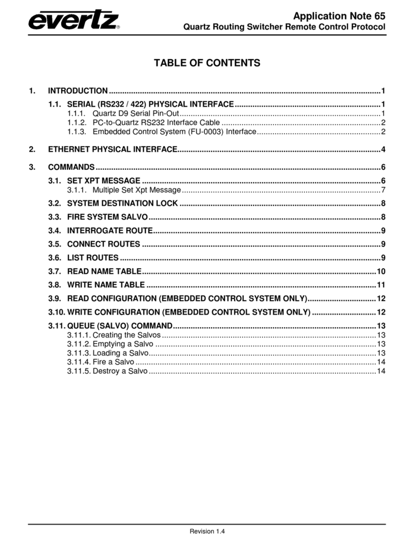
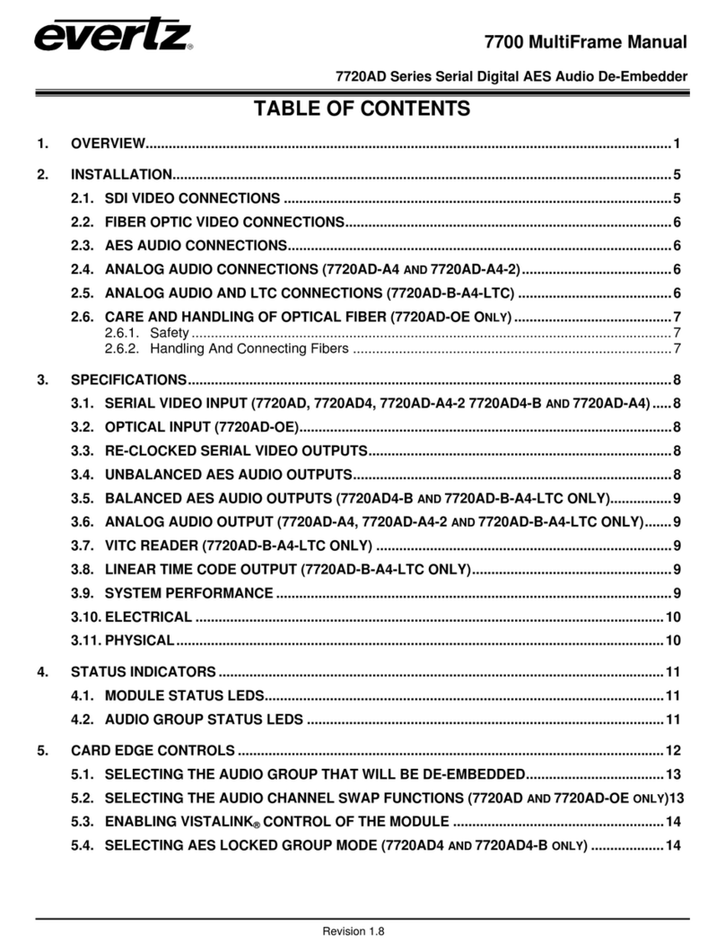
evertz 5950 User manual

Model 5950
LTC / VITC Timecode Reader
Character Inserter
Instruction Manual
© Copyright 1994, 2006
EVERTZ MICROSYSTEMS LTD.
5288 John Lucas Drive, Burlington, Ontario, Canada, L7L 5Z9
Phone: 905-335-3700 Fax: 905-335-3573
Sales: sales@evertz.com
Web Page: http://www.evertz.com
Revision 2.0 March 2006
The material contained in this manual consists of information that is the property of Evertz Microsystems and is
intended solely for the use of purchasers of the model 5950 Time code Reader. Evertz Microsystems expressly
prohibits the use of this manual for any purpose other than the operation of the 5950.
All rights reserved. No part of this publication may be reproduced without the express written permission of
Evertz Microsystems Ltd. Copies of this guide can be ordered from your Evertz products dealer or from Evertz
Microsystems.

INFORMATION TO USERS IN EUROPE
NOTE
CISPR 22 CLASS A DIGITAL DEVICE OR PERIPHERAL
This equipment has been tested and found to comply with the limits for a Class A digital device,
pursuant to the European Union EMC directive. These limits are designed to provide reasonable
protection against harmful interference when the equipment is operated in a commercial
environment. This equipment generates, uses, and can radiate radio frequency energy and, if not
installed and used in accordance with the instruction manual, may cause harmful interference to
radio communications. Operation of this equipment in a residential area is likely to cause harmful
interference in which case the user will be required to correct the interference at his own
expense.
INFORMATION TO USERS IN THE U.S.A.
NOTE
FCC CLASS A DIGITAL DEVICE OR PERIPHERAL
This equipment has been tested and found to comply with the limits for a Class A digital device,
pursuant to Part 15 of the FCC Rules. These limits are designed to provide reasonable
protection against harmful interference when the equipment is operated in a commercial
environment. This equipment generates, uses, and can radiate radio frequency energy and, if not
installed and used in accordance with the instruction manual, may cause harmful interference to
radio communications. Operation of this equipment in a residential area is likely to cause harmful
interference in which case the user will be required to correct the interference at his own
expense.
WARNING
Changes or Modifications not expressly approved by Evertz Microsystems Ltd. could void the
user’s authority to operate the equipment.
Use of unshielded plugs or cables may cause radiation interference. Properly shielded interface
cables with the shield connected to the chassis ground of the device must be used.

Model 5950 Time Code Reader Manual
REVISION HISTORY
REVISION DESCRIPTION DATE
1.0 Original issue May 94
1.1 Technical Description, Schematics and Parts Lists Jun 94
1.2 Editorial Changes Sep 94
2.0 Updated for Revision 2 hardware Mar 06
Information contained in this manual is believed to be accurate and reliable. However, Evertz assumes no responsibility for the use thereof nor
for the rights of third parties, which may be effected in any way by the use thereof. Any representations in this document concerning
performance of Evertz products are for informational use only and are not warranties of future performance, either express or implied. The
only warranty offered by Evertz in relation to this product is the Evertz standard limited warranty, stated in the sales contract or order
confirmation form.
Although every attempt has been made to accurately describe the features, installation and operation of this product in this manual, no
warranty is granted nor liability assumed in relation to any errors or omissions unless specifically undertaken in the Evertz sales contract or
order confirmation. Information contained in this manual is periodically updated and changes will be incorporated into subsequent editions. If
you encounter an error, please notify Evertz Customer Service department. Evertz reserves the right, without notice or liability, to make
changes in equipment design or specifications.

Model 5950 Time Code Reader Manual
Revision 2.0
This page left intentionally blank

Model 5950 Time Code Reader Manual
TABLE OF CONTENTS Revision 2.0 i
TABLE OF CONTENTS
1. INTRODUCTION .........................................................................................................................1-1
1.1. HOW TO USE THIS MANUAL....................................................................................................1-2
2. INSTALLATION...........................................................................................................................2-1
2.1. REAR PANEL CONNECTIONS..................................................................................................2-1
2.1.1. Linear Time Code Connections.....................................................................................2-1
2.1.2. Video Connections........................................................................................................2-1
2.1.3. Parallel Remote Control Connections...........................................................................2-2
2.1.4. Serial Port Connections - Rev 2 versions only..............................................................2-2
2.1.5. Power Connections.......................................................................................................2-3
2.2. MOUNTING .................................................................................................................................2-3
2.3. POWER REQUIREMENTS .........................................................................................................2-3
2.3.1. Selecting the Correct Mains Voltage – Rev 1 versions.................................................2-3
2.3.2. Power Requirements – Rev 2 versions.........................................................................2-4
2.3.3. Changing the Fuse – Rev 1 versions............................................................................2-4
2.3.4. Changing the Fuse – Rev 2 versions............................................................................2-4
2.4. READER VIDEO INPUT..............................................................................................................2-5
2.5. CHARACTER INSERTER VIDEO............................................................................................... 2-5
2.6. LINEAR TIME CODE IN/OUT .....................................................................................................2-5
2.7. SAMPLE CONFIGURATIONS ....................................................................................................2-6
3. OPERATING INSTRUCTIONS....................................................................................................3-1
3.1. FRONT PANEL OVERVIEW.......................................................................................................3-1
3.1.1. Overview of the Pushbuttons........................................................................................3-1
3.1.2. Status Indicators ...........................................................................................................3-2
3.2. FRONT PANEL DISPLAY FUNCTIONS..................................................................................... 3-3
3.2.1. Special Front Panel Indicators......................................................................................3-3
3.3. CHARACTER GENERATOR FUNCTIONS ................................................................................3-3
3.3.1. Selecting and Positioning the Individual Character Inserter Windows..........................3-3
3.3.2. Positioning the Overall Character Display.....................................................................3-4
3.3.3. Special VCG Indicators.................................................................................................3-4
3.3.4. Field Identification.........................................................................................................3-4
3.4. ON SCREEN PROGRAMMING MENU - OVERVIEW ................................................................3-4
3.5. PROGRAMMING THE READER SETUP FUNCTIONS.............................................................. 3-6

Model 5950 Time Code Reader Manual
TABLE OF CONTENTS Revision 2.0 ii
3.6. PROGRAMMING THE CHARACTER GENERATOR FUNCTIONS...........................................3-9
3.7. PROGRAMMING THE OVERALL CONFIGURATION FUNCTIONS .......................................3-10
3.8. PARALLEL REMOTE CONTROL FUNCTIONS.......................................................................3-12
4. TECHNICAL DESCRIPTION.......................................................................................................4-1
4.1. OVERVIEW..................................................................................................................................4-1
4.2. SPECIFICATIONS.......................................................................................................................4-2
4.2.1. LTC Reader...................................................................................................................4-2
4.2.2. LTC Translator..............................................................................................................4-2
4.2.3. VITC Reader.................................................................................................................4-2
4.2.4. Character Generator.....................................................................................................4-2
4.2.5. Parallel Remote Control................................................................................................4-2
4.2.6. Serial Port - Rev 2 Version Only...................................................................................4-2
4.2.7. Electrical........................................................................................................................4-3
4.2.8. Physical.........................................................................................................................4-3
4.3. DIP SWITCH FUNCTIONS..........................................................................................................4-3
4.4. USER ADJUSTMENTS AND DIAGNOSTICS ............................................................................4-3
4.4.1. Front Panel Diagnostics................................................................................................4-3
4.4.2. Calibrating the Character Generator.............................................................................4-4
4.5. UPDATING TO A NEW FIRMWARE VERSION .........................................................................4-4
4.5.1. Upgrading The Firmware ..............................................................................................4-5
Figures
Figure 2-1: Rear Panel Layout – Rev 1 versions of 5950............................................................2-1
Figure 2-2: Rear Panel Layout – Rev 2 versions of 5950............................................................2-1
Figure 2-3: Dubbing and Off-line Character Burn In.................................................................... 2-7
Figure 2-4: VITC Translation to LTC for Editing...........................................................................2-8
Figure 3-1: Front Panel Layout...................................................................................................3-1
Figure 3-2: On Screen Programming Menu Overview................................................................3-5
Figure 3-3: Overview of Front Panel Menu..................................................................................3-5
Figure 3-4: READER Drop Down Menu......................................................................................3-7
Figure 3-5: VCG Drop Down Menu..............................................................................................3-9
Figure 3-6: CONFIGURATION Drop Down Menu......................................................................3-11
Figure 4-1: DIP Switch Functions ................................................................................................4-3
Figure 4-2: Keyboard Scan Codes...............................................................................................4-4
Tables
Table 2-1: Parallel Remote Control Pin Definitions......................................................................2-2
Table 2-2: Serial Port Pin Definitions...........................................................................................2-2

Model 5950 Time Code Reader Manual
Revision 2.0
1. INTRODUCTION ....................................................................................................................... 1-1
1.1. HOW TO USE THIS MANUAL..................................................................................................1-2

Model 5950 Time Code Reader Manual
Revision 2.0
This page left intentionally blank

Model 5950 Time Code Reader Manual
INTRODUCTION Revision 2.0 Page 1-1
1. INTRODUCTION
The model 5950 LTC/VITC Timecode Reader combines the latest LSI
technology with sophisticated microcontroller firmware to provide a
powerful, flexible time code reader system. The model 5950 is an
LTC/VITC reader and multi-function character inserter. Its power and
flexibility are unsurpassed in time code reader applications. An
alphanumeric display can be quickly delegated to show the required data.
The model 5950 contains two separate readers that can be operated
independent of each other, or can be linked to form an auto LTC/VITC
reader. The model 5950 can be configured in one of three basic operating
modes:
•Full speed (1/30 to 70 times play) LTC reader.
•0 to 40X speed VITC reader
•Auto LTC/VITC reader automatically switches between LTC and
VITC inputs reading whichever is valid.
The model 5950 provides a fully decoded and regenerated play speed LTC
output, containing information related to the reader. In many VTR's, the
position of the LTC time code head relative to the video signal can vary
quite considerably from machine to machine, causing a code phase shift
relative to the video frame. When the reader is configured to read LTC, the
incoming LTC is fully decoded and regenerated. When incoming LTC is at
normal play speed, the output code is re-phased to the video, thus
compensating for any LTC code misalignments from the video. When the
reader is configured to read VITC, the LTC output provides an LTC
translation of the incoming VITC.
The recovery of recorded LTC time code at other than play speed has
always presented some degree of difficulty, particularly with low end 3/4"
and 1/2" recorders lacking a separate address track. The high speed
reader in the model 5950 employs sophisticated input conditioning and
clock and data separator circuits to reliably recover LTC over the full shuttle
and wind speed ranges of most VTR's.
The VITC reader is designed for use with non time base corrected video
signals. Although the use of time base correctors will enhance the
recovery range of the VITC reader, the amount of improvement is
dependent on the type of TBC and transport being used. The model 5950
contains all the necessary video processing circuits and therefore, requires
no external signals other than the video signal itself. The VITC reader's
line range can be easily programmed from the front panel, thus permitting
recovery of specific VITC data where multiple sets have been recorded.
The high resolution character inserter provides two independently
positionable windows to show time and user bits simultaneously. Three
character sizes and the choice of white or black characters with or without
contrasting background mask are selected from the front panel.
Model 5950 Time Code Reader Manual
INTRODUCTION Revision 2.0 Page 1-2
When displaying data recovered from a VITC source, the 'lookahead'
compensation can be turned off, allowing field accurate burn-ins of edited
material. The field number sequence will be displayed to the right of the
frames display. When the data being read was recorded in the non colour
frame mode, the field number sequence will be 1,2,1, etc. (1,2,3,4,1, etc.
for PAL). When the reader data was recorded in the colour frame mode,
the field number sequence will be 1,2,3,4,1, etc. (1,2,3,4,5,6,7,8,1, etc. for
PAL).
The Character inserter provides an on screen programming menu system,
which is used to configure the various operating modes. The use of drop
down menus, and dedicated programming keys, allows the model 5950 to
be conveniently configured for particular customer requirements.
There are two different versions of the 5950 hardware. Rev 1 versions
have the rear panel layout shown in Figure 2-1 and rev 2 versions have the
rear panel layout shown in Figure 2-2. The labels on the connectors are
mostly the same, but many of the connectors have been relocated to better
suit the layout of the new circuit board. The front panels of the units are
similar except that the rev 1 units have a 12 digit alphanumeric display and
the rev 2 units have a 16 digit alphanumeric display. Installation and
operation of the two versions is similar except where specifically noted.
1.1. HOW TO USE THIS MANUAL
This manual is organized into 4 chapters : Introduction, Installation,
Operation, and Technical Description.
Electrical safety warnings are marked with a double box with a warning
symbol to the left.
"Items of special note for all users are marked with a double box and a
notation symbol to the left.

Model 5950 Time Code Reader Manual
Revision 2.0
2. INSTALLATION...........................................................................................................................2-1
2.1. REAR PANEL CONNECTIONS..................................................................................................2-1
2.1.1. Linear Time Code Connections........................................................................................2-1
2.1.2. Video Connections...........................................................................................................2-1
2.1.3. Parallel Remote Control Connections..............................................................................2-2
2.1.4. Serial Port Connections - Rev 2 versions only.................................................................2-2
2.1.5. Power Connections..........................................................................................................2-3
2.2. MOUNTING .................................................................................................................................2-3
2.3. POWER REQUIREMENTS .........................................................................................................2-3
2.3.1. Selecting the Correct Mains Voltage – Rev 1 versions....................................................2-3
2.3.2. Power Requirements – Rev 2 versions............................................................................2-4
2.3.3. Changing the Fuse – Rev 1 versions...............................................................................2-4
2.3.4. Changing the Fuse – Rev 2 versions...............................................................................2-4
2.4. READER VIDEO INPUT..............................................................................................................2-5
2.5. CHARACTER INSERTER VIDEO............................................................................................... 2-5
2.6. LINEAR TIME CODE IN/OUT .....................................................................................................2-5
2.7. SAMPLE CONFIGURATIONS ....................................................................................................2-6
Figures
Figure 2-1: Rear Panel Layout – Rev 1 versions of 5950............................................................2-1
Figure 2-2: Rear Panel Layout – Rev 2 versions of 5950............................................................2-1
Figure 2-3: Dubbing and Off-line Character Burn In.................................................................... 2-6
Figure 2-4: VITC Translation to LTC for Editing...........................................................................2-7
Tables
Table 2-1: Parallel Remote Control Pin Definitions......................................................................2-2
Table 2-2: Serial Port Pin Definitions...........................................................................................2-2

Model 5950 Time Code Reader Manual
Revision 2.0
This page left intentionally blank

Model 5950 Time Code Reader Manual
INSTALLATION Revision 2.0 2-1
2. INSTALLATION
2.1. REAR PANEL CONNECTIONS
There are two different versions of the 5950 hardware. Rev 1 versions
have the rear panel layout shown in Figure 2-1 and rev 2 versions have the
rear panel layout shown in Figure 2-2. The labels on the connectors are
mostly the same, but many of the connectors have been relocated to better
suit the layout of the new circuit board. Installation and operation of the
two versions is similar except where specifically noted.
PUSH
115Vac
L
T
C
I
N
L
T
C
O
U
TREMOTE CONTROL
EVERTZ MICROSYSTEMS LTD.
AB
OUT
VIDEO CHAR
GEN
READER
model 5950
MADE IN CANADA
VITC IN
FUSE
115 V:
.25 A
230 V:
.125 A
Figure 2-1: Rear Panel Layout – Rev 1 versions of 5950
Figure 2-2: Rear Panel Layout – Rev 2 versions of 5950
The following sections describe the purpose of the rear panel connectors of
the 5950. Figure 2.1 above shows the rear panel connectors provided on
the model 5950. Sections 2.1.1 to 2.1.5 describe the specific signals that
should be connected to the 5950. Figure 2-3 and Figure 2-4 give sample
connection diagrams for connecting the model 5950.
2.1.1. Linear Time Code Connections
LTC OUT: A male XLR connector for output of SMPTE / EBU linear
timecode from the translator.
LTC IN: A female XLR connector for input of SMPTE / EBU linear
timecode for reader 1.
2.1.2. Video Connections
READER VITC IN A BNC loop for input of program video onto which
characters are to be inserted. If the video contains vertical
interval time code, it will be read by the reader when it is
configured in the VITC or AUTO modes This signal is also
used to provide a gen-lock reference for the LTC translator
output.

Model 5950 Time Code Reader Manual
INSTALLATION Revision 2.0 2-2
VIDEO CHAR GEN OUT A & B Two isolated BNC connectors with
identical outputs of program video with characters inserted.
This output is also used to display the on screen
programming menu and is normally connected to a video
monitor.
2.1.3. Parallel Remote Control Connections
PARALLEL A 9 pin D connector located on the rear panel labeled
PARALLEL (REMOTE CTL on Rev 1 versions) provides 6
parallel control inputs for remote control of some of the
model 5950 functions. The pinout of the D connector is as
follows:
Pin
# Name Description
1 GND Frame ground
2 VCG Ena VCG On/Off
3 FRZ Freeze Display
4 TM/UB TM/UB display select
5 --- Not used
6 LTC Ena LTC reader enable
7 VITC Ena VITC reader enable
8 --- Not used
9 --- Not used
Table 2-1: Parallel Remote Control Pin Definitions
2.1.4. Serial Port Connections - Rev 2 versions only
SERIAL: Rev 2 versions of the 5950 are fitted with a 9 pin
subminiature 'D' connector labeled SERIAL. This port is
used to update the firmware in the 5950 and is configured at
the factory for a ‘straight through RS-232 connection to a PC
COM port. The pinout of the D connector is as follows:
Pin
# Name Description
1 GND Chassis ground
2 TxD RS-232 Transmit Output
3 RxD RS-232 Receive Input
4
5 Sig Gnd RS-232 Signal Ground
6
7 RTS RS-232 RTS Input
8 CTS RS-232 CTS Output
9
Table 2-2: Serial Port Pin Definitions

Model 5950 Time Code Reader Manual
INSTALLATION Revision 2.0 2-3
2.1.5. Power Connections
LINE: Rev 1 versions of the 5950 may be set for either 115v/60 Hz or
230v/50 Hz AC operation. The voltage selector switch is
accessible on the rear panel. The line voltage connector
contains an integral slow blow fuse (and a spare one).
Rev 2 versions of the 5950 have a universal power supply that
auto detects input voltages in the range of 100 to 240VAC,
60 or 50 Hz.
CAUTION - To reduce the risk of electric shock, grounding of the centre pin
of the mains plug must be maintained
2.2. MOUNTING
The 5950 Time Code Reader is equipped with rack mounting angles and
fits into a standard 19 inch by 1 3/4 inch (483 mm x 45 mm) rack space.
The mounting angles may be removed if rack mounting is not desired.
2.3. POWER REQUIREMENTS
2.3.1. Selecting the Correct Mains Voltage – Rev 1 versions
Power requirements for Rev 1 versions are 115 or 230 volts AC at 50 or 60
Hz, switch selectable on the rear panel. Power should be applied by
connecting a 3 wire grounding type power supply cord to the power entry
module on the rear panel. The power cord should be minimum 18 AWG
wire size, type SVT marked VW-1, maximum 2.5 m in length.
Before connecting the line power, be sure to select the proper line voltage.
Also, check that the line fuse is rated for the correct value marked on the rear
panel.
The power entry module combines a standard IEC 320 power inlet
connector, voltage selector switch, two 5 x 20 mm fuse holders and an EMI
line filter.
To change the mains voltage setting on the earlier units, open the cover of
the power entry module using a small screwdriver. Remove the drum
selector switch, and re-insert it so that the desired voltage is visible through
the opening on the mains connector cover. Check that the correct fuse is
in use as shown in section below.

Model 5950 Time Code Reader Manual
INSTALLATION Revision 2.0 2-4
2.3.2. Power Requirements – Rev 2 versions
Power requirements for Rev 2 versions are 100 to 240 volts AC at 50 or 60
Hz. The later 5950 units have a universal power supply that automatically
senses the input voltage. Power should be applied by connecting a 3-wire
grounding type power supply cord to each of the power entry modules on
the rear panel. The power cord should be minimum 18 AWG wire size;
type SVT marked VW-1, maximum 2.5 m in length.
The power entry modules combine a standard power inlet connector, two 5
x 20 mm fuse holders and an EMI line filter.
2.3.3. Changing the Fuse – Rev 1 versions
The fuse holder in Rev 1 versions is located inside the power entry module.
To change the fuse, open the cover of the power entry module using a
small screwdriver. The fuse holder on the bottom contains the active fuse.
The one at the top contains a spare fuse. Pull the bottom fuse holder out
and place a fuse of the correct value in it. Use slo blo (time delay) 5 x 20
mm fuses rated for 250 Volts with the following current ratings:
For 115 Volt operation 250 mA
For 230 Volt operation 125 mA
Check that the line fuse is rated for the correct value marked on the rear
panel. Never replace with a fuse of greater value.
Make sure that the arrow is pointing down when you replace the fuse
holder. Close the door on the power entry module and connect the mains
voltage.
2.3.4. Changing the Fuse – Rev 2 versions
The fuse holder is located inside the power entry module. To change the
fuses, disconnect the line cord from the power entry module and pull out
the fuse holder from the power entry module using a small screwdriver.
The fuse holder contains two fuses, one for the line and one for the neutral
side of the mains connection. Pull out the blown fuse and place a fuse of
the correct value in its place. Use time delay 5 x 20 mm fuses rated for
250 Volts with a current rating of 1 amp. Carefully reinsert the fuse holder
into the power entry module.
Check that the line fuse is rated for the correct value marked on the rear
panel. Never replace with a fuse of greater value.

Model 5950 Time Code Reader Manual
INSTALLATION Revision 2.0 2-5
2.4. READER VIDEO INPUT
Video associated with the LTC code or video with VITC recorded on it is
connected to the READER VITC IN loop. The video input has a high
impedance input tapped off the loop through, therefore the input must be
terminated with 75 ohms at the end of the line. The input video signal is
also used as a reference for the LTC translator output when it is operated
in regenerate mode, and the incoming code is at play speed.
2.5. CHARACTER INSERTER VIDEO
The input video on which the characters are to be displayed is the same
video as the reader uses and is connected to the READER VITC IN loop.
The video input has a high impedance input tapped off the loop through,
therefore the input must be terminated with 75 ohms at the end of the line.
Two isolated character generator outputs labeled VCG OUT A and B, are
provided to drive a preview monitor and a video recorder. Characters are
keyed into the video connected to the READER VITC IN loop. Size,
position, and style of the character displays are controlled from the on
screen programming menu.
In order to use the on screen programming menu system, video must be
applied to the READER VITC IN loop and one of the VCG outputs must be
connected to a video monitor.
2.6. LINEAR TIME CODE IN/OUT
The LTC reader input connects to your head pre-amplifier output. When
using an unbalanced input to the reader, the signal should be applied to pin
3 of the LTC reader input connector. Normally, the unused input, (pin 2)
should be connected to ground (pin 1).
A fully decoded and regenerated play speed LTC output is provided
containing information related to the Reader. In many VTR's, the LTC time
code head position with respect to the video signal can vary quite
considerably from machine to machine causing a code phase shift relative
to the video frame. When the reader is configured to read LTC the
translator output can be operated in the regenerate or reshape mode.
(Reshape mode only available on Rev 1 versions) In reshape mode,
incoming LTC is restored to the proper waveform and output in phase with
the incoming LTC. In regenerate mode, the incoming LTC is fully decoded
and regenerated. When incoming LTC is at normal play speed, the output
code is re-phased to the video, thus compensating for any LTC code
misalignments from the video. When the reader is configured to read
VITC, the LTC output provides an LTC translation of the incoming VITC.
When the reader assignment is set to AUTO, the LTC output provides a
translated output of whichever reader is active.

Model 5950 Time Code Reader Manual
INSTALLATION Revision 2.0 2-6
"
When using the regenerated LTC output, the video from the tape being read must
be looped through the READER VITC IN loop. (See Section 2.4) to ensure correct
phasing of the LTC output to the video. In audio tape applications or other
situations where video cannot be connected to the video input, the phase of the
LTC out will be free running. On Rev 1 versions the user should use Reshape mode
for audio applications.
2.7. SAMPLE CONFIGURATIONS
Two sample installation setups are diagrammed below to help properly
connect the model 5950 into your system. For other applications contact
the factory.
Figure 2-3 illustrates the basic set-up for reading LTC and VITC, making
off-line cassette copies with character burn-ins, or for dubbing tapes with
regenerated time code. Longitudinal code misalignments from the video
frame are compensated and the regenerated LTC is properly timed to the
video. The source video must be connected to the READER VITC IN loop
of the model 5950 to ensure correct timing of the output LTC to the video.
12:35:40:00.3
10:12:24:45
PLAYBACK VTR
CASSETTE RECORDER MONITOR
VIDEO OUT (+VITC)LTC OUT
VDEO IN
+CHAR
LTC IN
PUSH
N
I
L
T
C
T
O
U
L
C
T
REMOTE CONTROL
EVERTZ MICROSYSTEMS LTD
115Vac
model 5950
VIDEO CHAR
AOUT
GEN
B
MADE IN CANADA
VITC IN
READER
.125 A
230 V:
.25 A
115 V:
FUSE
Figure 2-3: Dubbing and Off-line Character Burn In

Model 5950 Time Code Reader Manual
INSTALLATION Revision 2.0 2-7
Figure 2-4 illustrates the setup for a VITC/LTC editing system. Using the
model 5950 your existing editing system can use LTC only, VITC only or
both LTC and VITC together for both edit decision making and editing. The
video from each source VTR is looped though the respective model 5950,
which will read VITC whenever it is present on the video. It is important
that the VITC is recorded on vertical interval lines that will be reproduced
by your VTR in playback. See your VTR manual for further information. If
a time base corrector is used, the video output should be fed to the model
5950 prior to TBC processing because many TBC's blank the vertical
interval and eliminate the VITC. If it is desired to time base correct the
video before the model 5950, make sure that the lines containing the VITC
are passed through the TBC.
PLAYBACK VTR
VIDEO OUT (+VITC)
LTC OUT
EDITOR
LTC IN
PUSH
N
I
L
T
C
T
O
U
L
C
T
REMOTE CONTROL
EVERTZ MICROSYSTEMS LTD
115Vac
model 5950
VIDEO CHAR
AOUT
GEN
B
MADE IN CANADA
VITC IN
READER
.125 A
230 V:
.25 A
115 V:
FUSE
Figure 2-4: VITC Translation to LTC for Editing
The recovered VITC is translated to LTC by the model 5950, which can be
read by the LTC reader in the edit controller. The new LTC is generated at
approximately play speed so that the edit controller can read it during slow
motion decision making and also for cueing and parking the VTR during
editing. When the incoming code is at play speed, the LTC is synchronized
to the video, so that the edit controller can use it to synchronize the
playback and record VTRs during the edit pre-roll interval, just as if it would
have used the original LTC from the VTR.

Model 5950 Time Code Reader Manual
INSTALLATION Revision 2.0 2-8
If it is desired to record VITC on the record VTR, a VITC/LTC jam-sync
generator such as our 5010-VITC must be used in the place of the model
5950 on the record VTR. During the edit pre-roll, when the record VTR is
in playback, the jam-sync generator will follow the numbers read from the
record machine. When the record VTR switches from playback to record,
the jam-synced VITC will be recorded in the video without interruption. See
model 5010-VITC Instruction Manual for more detailed information.
Table of contents
Other evertz Network Hardware manuals

evertz
evertz 7700 Series User manual

evertz
evertz MetaCast 2 User manual

evertz
evertz 7700 Series User manual

evertz
evertz 7700 Series User manual

evertz
evertz TR-3200E User manual

evertz
evertz 7700 Series User manual

evertz
evertz 7700 Series User manual

evertz
evertz HD9625DSK User manual

evertz
evertz 7700 Series User manual

evertz
evertz VIP-X User guide

evertz
evertz 7720AE Series User manual

evertz
evertz 9531 User manual

evertz
evertz 9580 User manual

evertz
evertz 7700 Series User manual

evertz
evertz 7700 Series User manual

evertz
evertz 5700ACO User manual

evertz
evertz Topaz User guide

evertz
evertz 5601AC02 User manual

evertz
evertz 7700 Series User manual

evertz
evertz 3700FR Series User manual