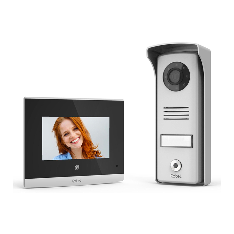
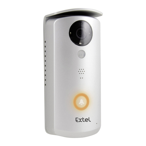
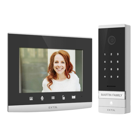
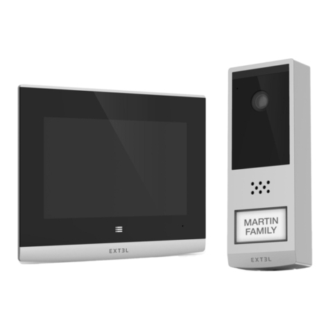
Extel WAVE User manual

Guide d’installation et d’utilisation
Installation and User Manual
Installatie- en gebruikersgids
Installations-und Bedienungsanleitung
Guía de instalación y de uso
Manual de instalação e utilização
Manuale d’uso e installazione
Οδηγός εγκατάστασης και χρήσης
GARANTIE
ANSANS
ANS
HOTLINE
?
i
WAV E
Connected videophone
Screen and intercom panel
REF. 720313
www.avidsen.com
V5

EXTEL - WAVE - 720313
Slave
+Master
Fig. 1
5x 6 6x 6 7x 1 8x 1
10 x 1 11 x 1
9x 1
1x 1 2x 1 3x 1 4x 1
Fig. 3
1
3
4
2
8
6
7
5
VIDEO GND SPK MICK KEYVCC
Slave
+Master
3 4 7 1265 8
1
2
Fig. 2
10
9
11

EXTEL - WAVE - 720313
Fig. 4
Fig. 4’
1
5
6
7
3
4
Eco
Power
PAIR1
RESET
LOCK COMNO
- +
-
+
~~
2

EXTEL - WAVE - 720313
Fig. 4’
Eco
Power
PAIR1
RESET
LOCK COMNO
- +
-
+
~~
Fig. 5 50cm
160cm 150cm

EXTEL - WAVE - 720313
Fig. 6
49.3 mm
Fig. 6'
Fig. 7
350
8Go
WiFi
Smartphone Router/
Gateway
Internet
Contents of the kit
*: Option
**: Not included
***: Unobstructed
range

EXTEL - WAVE - 720313
Fig. 8

EXTEL - WAVE - 720313
Fig. 9

EXTEL - WAVE - 720313

EXTEL - WAVE - 720313 en - 1
CONTENTS
A - KIT CONTENTS .........................................................................................................................................................02
B - DESCRIPTION OF MONITOR ...............................................................................................................................02
C - DESCRIPTION OF THE INTERCOM PANEL..................................................................................................02
D - DESCRIPTION OF THE POWERBOX ..............................................................................................................02
E - INSTALLATION.......................................................................................................................................................... 03
1 - Wiring
2 - Intercom panel installation
3 - Installing the powerbox
4 - Connecting an electric strike plate
5 - Connecting a motor drive
6 - Pairing the monitor with the powerbox
7 - Smartphone application
F - MONITOR USER MANUAL.....................................................................................................................................13
1 - Button functions
2 - Main menu
3 - Sound adjustment menu
4 - WiFi settings
5 - Advanced settings
G - TECHNICAL SETTINGS ........................................................................................................................................16
H - WARRANTY.................................................................................................................................................................17
I - SAFETY INSTRUCTIONS ........................................................................................................................................18
J - TECHNICAL AND LEGAL INFORMATION.......................................................................................................19
1 - Declaration of conformity

EXTEL - WAVE - 720313
en - 2
A - KIT CONTENTS
B - DESCRIPTION OF MONITOR
1Monitor
2Intercom panel
3Surface mounting bracket
4Antenna
5Plug
6Fixing screws for monitor bracket and surface
mounting bracket
17" colour screen
2Microphone
3
Screen off: Intercom panel preview (surveillance
mode, only when the intercom panel is not battery-
powered)
Menu: left arrow or up arrow
Call in progress: takes a photo
4
During communication: Starts/ends a call
In surveillance mode: initiates
communication
Menu: right arrow or down arrow
5
Screen off: Enables touch keys and access
to the time and then the menu by pressing
again
Menu: OK (selection button).
Call in progress: Access the image settings
7Hexagonal screwdriver 1.5mm
8Plug-in power supply for the screen
9PowerBox
10 Flat cable (1 m)
11 Additional power supply for the PowerBox
6
In call or surveillance mode:
Opening of the
electric strike plate (only when the intercom
panel is not battery-powered)
7
In call or surveillance mode: Opens dry
contact (gate motor drive)
Menu: Back/Exit (back button to parent
menu)
8Loudspeaker
9Jack connector for powering
10 SD memory card slot (8GB, included)
11 QR code to identify the doorkeeper
12 Antenna
Fig. 1
Fig. 2
C - DESCRIPTION OF THE
INTERCOM PANEL
1Protective case
2Camera and infrared LEDs
3Loudspeaker
4
Name holder (the transparent plastic can be peeled
back to write on the label)
5Microphone
6Call button
7Dawn-to-dusk cell capable of detecting
ambient brightness
8Connectors for the PowerBox
1Antenna
2Battery compartment (4 x LR20, not included)
3Pairing button (red)
4Reset button (black)
5Connectors for power supply, strike plate and
motor drive
6Connectors for the intercom panel
7Eco mode management switch
Fig. 3 Fig. 4
D - DESCRIPTION OF
THE POWERBOX
EXTEL - WAVE - 720313
en - 3
E - INSTALLATION
1 - WIRING
• The wiring diagrams can be found in:
- Fig. 7: Generic diagram
- Fig. 8: Connection diagram between the PowerBox and the intercom panel
-Fig9: Connection diagram of the Powerbox to the optional power supply, electric strike plate and gate
motor drive
• Do not increase the number of insulating screw joints or connectors on the connecting wire between the
intercom panel and the PowerBox
• You can connect and use an electric strike plate (not provided) with your intercom panel, with mechanical
memory. The Extel Wave videophone can only activate an electric strike plate when the PowerBox is powered
by the power supply unit provided and Power mode is enabled.
• To ensure good audio and video quality, the PowerBox should be installed on the back of your pillar in an open
environment to guarantee optimal communication between your intercom panel and the monitor in your home.
2 - INSTALLING THE INTERCOM PANEL
- Fig6 . Assembly
1. Loosen the screw at the bottom of the intercom panel to release it from the mounting case
(Caution: use the tool provided to unscrew the intercom panel, do not unscrew the intercom panel screw by
hand: the screw does not have to be removed to release the panel from the wall mount)
2. Screw the mounting case to the wall as recommended in Fig 5 .
3. Place a silicone seal between the mounting case and the wall to prevent the infiltration of water. Do not use an
acetic acid-based silicone (smells like vinegar)
4. Connect the wires according to the wiring diagram (Fig 8 )
5. Fit the intercom panel into the mounting case
6. Tighten the intercom panel screw
Important: do not expose the camera to direct sunlight or place it facing a reflective surface.
Tip: it is recommended that the wires be passed through a sheath to protect them from impacts and inclement
weather.
- Fig6’ . Mounting with a recess case (not supplied - ref 720312)
For flush mounting, you will need a recess case (not supplied - ref 720312).
An opening of 200 mm (H) x 70 mm (W) x 26 mm (D) is required.
1. Loosen the screw at the bottom of the intercom panel to release it from the mounting case
(Caution: do not unscrew the intercom panel screw by hand: the screw does not have to be removed to release
the panel from the wall mount)
2. Screw the recess case to the wall as recommended in Fig5.
3.
Place a silicone seal between the recess case and the wall to prevent the infiltration of water.
Do not use an acetic acid-based silicone (smells like vinegar)
4. Connect the wires according to the wiring diagram (Fig8)
5. Fit the intercom panel into the recess case
6. Tighten the intercom panel screw

EXTEL - WAVE - 720313
en - 4
E - INSTALLATION
3 - INSTALLING THE POWERBOX
1. Insert 4 LR20 batteries in the electronic case or connect the power supply (Fig.9) to conduct the radio range
tests. Whenever possible, the antenna must be clear of any metal, source of interference or obstacles between
your case and your home; in particular, no contact between the antenna and tree leaves or branches. It must
also be placed high enough (approximately 1.60 m from the ground) and in a vertical position to obtain optimum
performance.
Note: if the quality of transmission is insufficient, move the PowerBox to find a better position for the antenna
(higher and far from any obstacle).
2. Once the ideal location has been determined, carry out the final assembly.
3. Using 2 screws, secure the case via the 2 holes at the top and bottom, the antenna being at the top (fig 4’)
4. Don’t forget to run the connection cable to the intercom panel first through the hole in the pillar and the
connecting wires to the gate motor drive or the electric strike plate.
Note: Do not install any antenna other than the original one.
Managing Eco - Power mode
4 x LR20
Eco
Power
Eco
Power
Eco
Power
4 - CONNECTING AN ELECTRIC STRIKE PLATE
Directly connect the strike plate to the LOCK + and LOCK - terminals of the PowerBox (no polarity to be observed).
Important: The electric strike plate opening function is only available when the PowerBox is powered by the power
supply unit provided (which itself is connected to the 230V power supply) and when Power mode is enabled.
Note that this function is only valid if the screen is on. The unit may buzz at the time the command is given.
For wiring, please refer to the diagram in Fig 9 .
Important:
• The maximum distance between the intercom panel and the electric strike plate or electric lock is 50 m
maximum. The wire size to be used is 0.75mm².
• The use of a 12 V/1.1 A max. electric strike plate with WECA mechanical memory (Extel reference 109021 or
109031) or WECA 5001/2 10 SER R1 (reference 150011) is recommended.
5 - CONNECTING A MOTOR DRIVE
Directly connect it to the COM and NO terminals of the PowerBox (no polarity to be observed).
Note that this function is only valid if the screen is on. The panel provides a "dry" contact
connection, without an electric current, to connect to the button for your automated gate. For wiring, please refer
to the diagram in Fig 9 .
Important:
• The maximum distance between the intercom panel and the gate motor drive is 50 m maximum. The wire size
to be used is 0.75mm².
• The product has been tested and approved with Thomson, Extel and Avidsen gate motors, which can be found
at maisonic.fr

EXTEL - WAVE - 720313
en - 5
6 - PAIRING THE MONITOR WITH THE POWERBOX
To simplify product installation, the screen and the PowerBox of your kit have already been paired at the factory.
If pairing has not been successfully completed during the production stage, you can do it by following the steps
below
Note: For example, you can place the 2 products close by on a table or any other flat base. You may get a
feedback effect if the intercom panel and the monitor are too close (screeching noise).
1 - Put the screen in pairing mode
In the menu of your videophone, go to the settings sub-menu
In the settings sub-menu, select the second line and launch the pairing mode
E - INSTALLATION

EXTEL - WAVE - 720313
en - 6
Your screen is in pairing mode when a 60sec countdown timer starts
2 - Put the PowerBox in pairing mode
Eco
Power
PAIR1
RESET
LOCK COM NO
- +
-
+
~~
To put the PowerBox in pairing mode, press the red pairing button once for 1 sec as shown above.
3 - Pair the intercom panel with the screen
After pressing the PowerBox pairing button and launching the screen timer, press the intercom panel’s call button.
The screen starts ringing.
Note: you must press the intercom panel button before the screen timer reaches 0.
E - INSTALLATION

EXTEL - WAVE - 720313
en - 7
7 - SMARTPHONE APPLICATION
Connecting a monitor to the WiFi network
1- Download the Extel Connect application onto your smartphone. From the Apple store or Play store
2- From the monitor, go to the WiFi menu then the pairing with your smartphone sub-menu
Note: If the icon does not appear on the third line, reset the WiFi by clicking on RESET, then wait for the
icon to appear (about 30 seconds).
The Extel Wave videophone works with all types of 2.4GHz or 5GHz WiFi. However, for optimum performance, we
recommend connecting your videophone to a 5GHz WiFi.
Before starting the pairing procedure, it is advisable to connect your smartphone to the WiFi to which you wish to
connect the videophone.
3 - From the Extel Connect application, click on + to add a device.
E - INSTALLATION

EXTEL - WAVE - 720313
en - 8
4 - Click on “nouvel appareil” (new device) and then
“suivant” (next)
The application reminds you that the screen of your
videophone must be in pairing mode, and indicates
where to find the QR Code you need to scan. Click on
“suivant” (next).
Scan the QR Code of your videophone as shown on
the previous page.
The WiFi network to which your phone is connected
appears. To change it, click on . If no network
appears, your phone is probably in 3G/4G.
When the WiFi network you want appears, enter the
password.
E - INSTALLATION

EXTEL - WAVE - 720313
en - 9
E - INSTALLATION
Your mobile phone emits a sound that allows it to
connect to your videophone.
Place your phone next to the monitor microphone.
Choose the name of your videophone.
Your videophone is now connected to the WiFi network
and your smartphone can receive
calls.
The first time you view the video stream, you will be
asked to customise your password.
Note: We remind you that the surveillance mode is not
available when the videophone is battery-powered.
After pairing with your smartphone, you must press the
call button to view the video stream.
Add a smartphone to a connected videophone
1- Download the Extel Connect application to your
smartphone from the Apple store or Play store
Note: Disable the smartphone's WiFi smart network
mode if it is activated.
2 - From the Extel Connect application, click
on + to add a device.

EXTEL - WAVE - 720313
en - 10
E - INSTALLATION
3. Click on “appareil connecté au réseau” (device
connected to the network), then “appareil connecté”
(device connected).
Make sure that the smartphone is connected to the
same WiFi network as the monitor.
4. Enter the name you want to give your device.
Scan the monitor's QR code or enter the monitor ID
(information available in the WiFi settings and
password).
Important: When you click on the QR Code to the right
of the UID line, you will be able to scan the videophone
monitor's QR Code and get its UID faster.
Click on Save.
If the videophone is not nearby, you can scan the
barcode in the Extel Connect owner's application.
The barcode is available under the “Inviter un ami” (Invite
a friend) menu in the already connected application.
5. Your smartphone can now receive calls from your
videophone.
Interface function
Contains the different devices and enables
switching to monitoring mode.
Enables you to add a device.
Click the image to enter monitoring mode. The
monitoring option is only available when the PowerBox
is mains-powered (via the power supply unit provided)
Activate/Deactivate the sound
Take a video
Take a photo

EXTEL - WAVE - 720313
en - 11
E - INSTALLATION
Full-screen mode
Open the electric strike plate or the gate
Press and hold to speak to
the visitor.
1
2
3
4
5
1Used to rename your videophone
2Used to change the opening command
password (disabled by default) and video
password
3Invite a friend
4Enables or disables call notifications
5Used to delete a device from the account
Warning: is used to modify and is used to
validate.
• QR Code: this QR code allows your
friends or family to simply connect to your
Extel Wave videophone. See chapter:
“Add a smartphone to a connected videophone”.
• Link: Share your Extel Wave videophone login details
with friends and family.
• Have your friends download the Extel Connect
application.
• Share the link using the messaging service of your
choice by pressing ‘Share’.
• Securely share your password.
• When you click on the link, your friend's Extel Connect

EXTEL - WAVE - 720313
en - 12
E - INSTALLATION
application automatically opens and all information
on the videophone is pre-populated.
• The application asks you to enter the password you
have already chosen.
• Your friend is now connected to your videophone.
Used to delete recordings
Groups recordings
Allows you to edit photos (delete, sort and group)
Groups saved photos.
This manual suits for next models
1
Table of contents
Other Extel Telephone manuals

Extel
Extel 720320 User manual

Extel
Extel WAVE 2 User manual

Extel
Extel WEVP 252 BIS User manual

Extel
Extel WEVP 630 E BIS User manual

Extel
Extel MOMBO User manual

Extel
Extel Compact User manual

Extel
Extel CB BUSPRO 2 User manual

Extel
Extel Karo HD-2660 User manual

Extel
Extel WEVPSF 659 User manual

Extel
Extel WEVA DB-9035E User manual