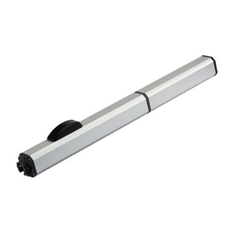
FAAC 940SM Series User manual

940SM-SMD
940SM-SMD
para la naturaleza
100% papel reciclado
ist umweltfreundlich
100% Altpapier
pour la nature
papier recyclé 100%
for nature
recycled paper 100%
carta riciclata 100%
per la natura

1
ENGLISH ENGLISH
1) CAUTION!Itisimportant forpersonalsafetytofollow all theinstructions
carefully. Incorrect installation or misuse of the product may cause
peopleseriousharm.
2) Readtheinstructionscarefullybeforestartingtoinstalltheproduct.
3) Packagingmaterial(plastic,polystyrene,etc.)mustnotbeleftwithinreach
ofchildrenasitisapotentialsourceofdanger.
4) Keeptheinstructions forfuturereference.
5) Thisproductwasdesignedandmanufacturedstrictlyfortheuseindicated
inthisdocumentation.Anyothernotexpresslyindicatedusemaydamage
theproductand/orbeasourceofdanger.
6) FAACacceptsnoresponsibilityduetoimproperuseoftheautomated
systemoruseotherthanthatintended.
7) Do not install the equipment in an area subject to explosion hazard:
inflammablegasesorfumesareaserioussafetyhazard.
8) ThesystemmustbecarriedoutincompliancewiththefollowingStandards:
EN12604,EN12605,EN12453,EN12445.Toobtainanadequatelevelof
safety in non EU countries, the above mentioned Standards must be
observedinadditiontonationalStandards.
9) FAACwillnotacceptresponsibilityiftheprinciplesofGoodWorkmanship
aredisregardedinconstructingtheclosingelementstobemotorised,and
ifanydeformationoccursduringuseofthesaidelements.
10) Beforecarryingoutanyworkonthesystem,switchoffthepowersupply.
11) Themainspower supplyoftheautomatedsystemmustbefittedwithaall-
pole switchwithcontactopeningdistanceof3mmorgreater.Useofa6A
thermalbreakerwithall-polecircuitbreakisrecommended.
12) Makesurethereisadifferentialswitchwith0.03Athresholdupstreamofthe
system.
13) Checkthattheearthingsystemiscorrectlymadeandconnecttheclosure
metalpartstoit.
14) Theautomatedsystemincludesanintrinsicanti-crushingdeviceconsisting
ofatorquecontrolwhich,however,mustbeinstalledtogetherwithother
safetydevices.
15) The safety devices (EN 12978 Standard) protect any dangerous areas
against Mechanical movement risks, such ascrushing, dragging,and
shearing.
CE DECLARATION OF CONFORMITY FOR MACHINES
(DIRECTIVE98/37/EC)
Manufacturer: FAAC S.p.A.
Address: Via Benini, 1 - 40069 Zola Predosa BOLOGNA - ITALY
Declares that: 940 SM - SMD mod. operator
• is built to be integrated into a machine or to be assembled with other machinery to create a machine under
the provisions of Directive 98/37/EC;
• conforms to the essential safety requirements of the following EEC directives:
73/23/EEC and subsequent amendment 93/68/EEC.
89/336/EEC and subsequent amendment 92/31/EEC and 93/68/EEC
and also declares that it is prohibited to put into service the machinery until the machine in which it will be
integrated or of which it will become a component has been identified and declared as conforming to the
conditions of Directive 98/37/EC.
Bologna, 01 January 2003 The Managing Director
A. Bassi
16) Awarningsignadequatelyfittedontheleaves,inadditiontothedevices
mentionedunderpoint"15",mustbeusedforeachsystem.
17) FAACacceptsnoresponsibilityregardingsafetyandcorrectoperation
oftheautomatedsystem, shouldcomponentsmadebymanufacturers
otherthanFAACbe usedinthesystem.
18) UseonlyFAACoriginalsparepartsfor maintenance.
19) Donotmakeanyalterationstothecomponentsoftheautomatedsystem.
20) Theinstallershallsupplyfullinformationregardingmanualoperationof
thesystemincaseofanemergency.
21) Donotallowchildrenorotherpersonstostandneartheproductwhilein
operation.
22) Keep remote controls or any other pulse generator well away from
children, to prevent the automated system from being activated
accidentally.
23) The user must refrain from attempting to repair or adjust the system
personallyandshouldcontactqualifiedpersonnelonly.
24) Anythingnotexpresslyprovidedforintheseinstructionsisnotpermitted.
WARNINGS FOR THE INSTALLER
GENERAL SAFETY OBLIGATIONS

2
ENGLISHENGLISH
KEY TO PROFILES
SUPPORT PROFILE
HOUSING PROFILE
SLIDING PROFILE
CLOSING PROFILE FOR STANDARD AUTOMATED SYSTEM
LEAF ATTACHMENT PROFILE
LEAF BOTTOM PROFILE
GRIPPER FOR GLASS LEAVES
BOTTOM SLIDING BLOCK FOR GLASS LEAF

3
ENGLISH ENGLISH
Tx
Rx
230V~
Fig.1
Powersupply 230V~
N°
DESCRIPTION CABLES
Externalradar
Internalradar
Transmitter
Receiver
SD-Keeper
4x0.25mm²
4x0.25mm²
2x0.25mm²
3x0.25mm²
2x0.5mm²max50m
SD-Keeperswitch
withlock key 2x0.5mm²
Emerg/Key/Reset
controlpush-buttons 2x0.5mm²
3x1.5mm²
TAB. 1 TECHNICALSPECIFICATIONS
AVAILABLE MODELS
Head profile
Number of leaves
Leaf maximum weight
Width of free transit space Vp
Max thickness of framed leaf
Max absorbed power
Power supply
Protection class
Anti-crushing activation
Operating ambient temperature
Usefrequency
Motor power supply
Head profile length
Opening speed adjustment (load-free)
Closing speed adjustment (load-free)
Partialopening adjustment
Pausetimeadjustment
Nightpause timeadjustment
Failsafeonphotocells
IP 23 (indoor use)
940SMD1
940SM1 940SM2 940SMD2
Support Support
1212
800÷3000 700÷3000 800÷3000700÷3000
100%
-20°C ÷ +55°C
115V/ 230V~ 50/60Hz
100W
24Vdc
5 ÷ 70 cm/sec.
5 ÷ 70 cm/sec. 10 ÷ 140 cm/sec.
10 ÷ 140 cm/sec.
on opening /closing
0 ÷ 90 sec.
0 ÷ 240 sec.
140 110 + 110 250 180 + 180
10% ÷ 90%
60 mm
1. ELECTRICALEQUIPMENT
can be disabled
200W
See figs. 3 to 8

4
ENGLISHENGLISH
15
15
9,5
179,5
34,5±10
25
50
130,540
100
180
173
Fig.2

5
ENGLISH ENGLISH
Emergencybatteries(fig.1ref.)
In the event of a mains power cut, on-battery operation
providesarange of 30 minutes at100%use frequency.
The battery charge status test is automatic and indicated by
aLED.
Thechargecontrolboardisdesignedforremoteactivationof
a'batteryoperating'signal.
3.2 Supplementaryaccessories
Thesearethe peripheralaccessoriesforcompletingthe
automatedsystem.
-Miniswitch photocells
-T20E:outdoorkey-operatedselectorswitch
-T20I:flush-fitting key-operatedselectorswitch
-T21EF:Outdoorkey-operatedselectorswitchdesignedfor
motorrelease
-T21IF:Flush-fitting key-operated selectorswitchdesignedfor
motorrelease
-Detectionsensors.
-SD Keeper
3.3 Doorframeaccessories
Tofacilitateadaptingthe doorframeprofiletothecarriages
andtoenablecorrectfinishingoftheinstallation,FAACoffers
thefollowingseriesofarticles:
Closing profile (fig.2ref.)
Available in natural and anodised aluminium versions, the
profileisusedforclosingthespacebetweenthemobileleaf
and the wall on which the head profile is secured.
Brush for closing profiles (fig. 2 ref. )
Preventsdustreachinginsidetheheadprofile.
Pairofslidingblocks(fig.13ref.2)
Supplied as a pair, they can be secured to the wall (or on the
stationaryleaf)ordirectlyonthefloor.
Bottomtrackprofile(fig.13ref.)
Allowsthe bottom leaf profile to adapt to the sliding block
mentionedabove.
Brushfor bottomtrack profile(fig.13ref.)
Thiscompletestheon-groundtracksystem.
Leafattachmentprofile(fig.16ref.)
Allowsthe top leaf profile to adapt to thecarriage
attachments.
Pairofbottomslidingblocksforglass leaf
Theyenable the glass leaves to slide.
4. HEAD PROFILE CONFIGURATION
Tocorrectlypositiontheheadprofile parts, refer tothe
dimensionsinfigures3,4and5formodelSMandfigures6,7
and8fortwin-motormodel(SDM).
WiththeFAACseries940SMsystems,single-or double-leaf
sliding doors can be automatically activated, managed and
controlled.
TheFAACseries940automatedsystemsaresuppliedfully
assembled,wiredandtestedin the configurationrequested
by the customer on the order form, or supplied as a kit.
Anautomationheadprofile(fig.1)consistsofthefollowing
parts:
ProfileSM (fig.2ref.)
Thisis the supportprofile which isused when the head profile
canbeentirelyfitted on a bearing structure. Theprofile's
slidingtrack is coated with a special plastic materialwhich, in
additiontoprotecting thealuminiumprofileagainstwear,
ensuressilentoperationwithaverylowfrictioncoefficient.
Leafsupportcarriages(fig.1ref.)
Thecarriagesareprovided with twowheelsonballbearings,
a counter wheel on the lower part, and a screw system for
adjustingleafheight.
Motorunit(fig.1 ref. )
The DC motor is supplied with an encoder and a leaf locking
system(accessory).
Control unit (fig.1ref.)
Whenthe microprocessorcontrolunit ispoweredup, it
executesaninitialisationprocessofthedoor'sfunctional
parameters.
Transformer(fig.1ref.)
Openingmechanicalstop(fig.1ref.)
Transmission pulley unit (fig.1ref.)
Secondmotor(fig.1ref.)
Drivechain(fig.1ref.)
3. ACCESSORIES
FAAChasthreegroupsofarticlescomplementingthe
installationoftheautomaticdoor.
3.1 Supplied accessories for the head profile
Thesearethe articleswhich,followingarequest ontheorder
form,areassembled ontheheadprofiledirectlyby FAAC.
Theseaccessories,whichcanbe,ifnecessary,installedlater
on,areasfollows:
Fronthousing(fig.2ref.)
The front housing is available in natural or anodised
aluminium.Thesidepanelsfullyenclosethesystem.
Motor lock unit
Themotorlock unitguarantees mechanical locking of the
doorinanyposition.Asingletypeofmotorlockisusedfor
eithersingle-ordouble-leafapplications.
Themotorlockis suppliedwithaninternalrelease device(fig.
1ref.)enablingemergencyopeningifnecessary;itisalso
designedforinstallationoftheexternalrelease(paragraph3.2
key push-buttons T21EF and T21IF). The motor lock unit acts
directlyonthemotor bylockingitmechanically.
Motorlockcontrol
Thiscontrolsifthemotorlockoperatingefficientlyandchecksifthe
doorhasactuallyclosed.Ifnecessary,thesystemisdesignedfor
remoteactivationofanindicator-lightorbuzzer.
940SM-SMD SERIES AUTOMATIC DOORS
2. DESCRIPTION AND TECHNICAL SPECIFICATIONS
6
ENGLISHENGLISH
CI
70
Vp
B
Lt
Vp Lt B C D I
700 1500 490 335 1870 865
800 1700 590 535 2070 965
900 1900 690 635 2270 1065
1000 2100 790 735 2470 1165
1100 2300 890 835 2670 1265
1200 2500 990 935 2870 1365
1300 2700 1090 1035 3070 1465
1400 2900 1190 1135 3270 1565
1500 3100 1290 1235 3470 1665
1600 3300 1390 1335 3670 1765
1700 3500 1490 1435 3870 1865
1800 3700 1590 1535 4070 1965
1900 3900 1690 1635 4270 2065
2000 4100 1790 1735 4470 2165
2100 4300 1890 1835 4670 2265
2200 4500 1990 1935 4870 2365
2300 4700 2090 2035 5070 2465
2400 4900 2190 2135 5270 2565
2500 5100 2290 2235 5470 2665
2600 5300 2390 2335 5670 2765
2700 5500 2490 2435 5870 2865
2800 5700 2590 2535 6070 2965
2900 5900 2690 2635 6270 3065
3000 6100 2790 2735 6470 3165
Vp = Free transit space
Lt = Head profile length
B=Securingdistanceofcarriagesonslidingleaf
C=Motorpositioningdimension
D=Lengthoftransmissionbelt
I=Motor/transmissionunitdistance
Fig.3
940 SM Right opening
SM transmission unit
SM Control board unit
Motor
Lt = Vp x 2 + 100
Transformer/buffer
batteriesunit

7
ENGLISH ENGLISH
I
C
Vp
70B
Lt
Vp Lt B C D I
700 1500 510 450 1990 925
800 1700 590 585 2070 965
900 1900 690 685 2270 1065
1000 2100 790 785 2470 1165
1100 2300 890 885 2670 1265
1200 2500 990 985 2870 1365
1300 2700 1090 1085 3070 1465
1400 2900 1190 1185 3270 1565
1500 3100 1290 1285 3470 1665
1600 3300 1390 1385 3670 1765
1700 3500 1490 1485 3870 1865
1800 3700 1590 1585 4070 1965
1900 3900 1690 1685 4270 2065
2000 4100 1790 1785 4470 2165
2100 4300 1890 1885 4670 2265
2200 4500 1990 1985 4870 2365
2300 4700 2090 2085 5070 2465
2400 4900 2190 2185 5270 2565
2500 5100 2290 2285 5470 2665
2600 5300 2390 2385 5670 2765
2700 5500 2490 2485 5870 2865
2800 5700 2590 2585 6070 2965
2900 5900 2690 2685 6270 3065
3000 6100 2790 2785 6470 3165
Fig.4
940 SM Left opening
SM transmission unit
SM Control board unit
Lt = Vp x 2 + 100
Vp = Free transit space
Lt = Head profile length
B=Securingdistanceofcarriagesonslidingleaf
C=Motorpositioningdimension
D=Lengthoftransmissionbelt
I=Motor/transmissionunitdistance
Motor Transformer/buffer
batteriesunit

8
ENGLISHENGLISH
CI
Lt
2727
Vp
70B
B70
Vp Lt B C D I
800 1700 225 205 2710 1285
900 1900 275 257,5 2910 1385
1000 2100 325 307,5 3110 1485
1100 2300 375 357,5 3310 1585
1200 2500 425 407,5 3510 1685
1300 2700 475 457,5 3710 1785
1400 2900 525 507,5 3910 1885
1500 3100 575 557,5 4110 1985
1600 3300 625 607,5 4310 2085
1700 3500 675 657,5 4510 2185
1800 3700 725 707,5 4710 2285
1900 3900 775 757,5 4910 2385
2000 4100 825 807,5 5110 2485
2100 4300 875 857,5 5310 2585
2200 4500 925 907,5 5510 2685
2300 4700 975 957,5 5710 2785
2400 4900 1025 1007,5 5910 2885
2500 5100 1075 1057,5 6110 2985
2600 5300 1125 1107,5 6310 3085
2700 5500 1175 1157,5 6510 3185
2800 5700 1225 1207,5 6710 3285
2900 5900 1275 1257,5 6910 3385
3000 6100 1325 1307,5 7110 3485
Fig.5
940 SM Double-leaf
SM transmission unit
SM Control board unit
Motor
Lt = Vp x 2 + 100
Transformer/buffer
batteriesunit
Vp = Free transit space
Lt = Head profile length
B=Securingdistanceofcarriagesonslidingleaf
C=Motorpositioningdimension
D=Lengthoftransmissionbelt
I=Motor/transmissionunitdistance

9
ENGLISH ENGLISH
CI
Lt
70
Z(100)
Vp
B
Fig.6
Vp Lt B C D I
700 1600 490 420 2040 950
800 1800 590 435 2240 1050
900 2000 690 535 2440 1150
1000 2200 790 635 2640 1250
1100 2400 890 735 2840 1350
1200 2500 990 835 2870 1365
1300 2700 1090 935 3070 1465
1400 2900 1190 1035 3270 1565
1500 3100 1290 1135 3470 1665
1600 3300 1390 1235 3670 1765
1700 3500 1490 1335 3870 1865
1800 3700 1590 1435 4070 1965
1900 3900 1690 1535 4270 2065
2000 4100 1790 1635 4470 2165
2100 4300 1890 1735 4670 2265
2200 4500 1990 1835 4870 2365
2300 4700 2090 1935 5070 2465
2400 4900 2190 2035 5270 2565
2500 5100 2290 2135 5470 2665
2600 5300 2390 2235 5670 2765
2700 5500 2490 2335 5870 2865
2800 5700 2590 2435 6070 2965
2900 5900 2690 2535 6270 3065
3000 6100 2790 2635 6470 3165
940 SMD Right opening
Vp = Free transit space
Lt = Head profile length
B=Securingdistanceofcarriagesonsliding
leaf
C=Motorpositioningdimension
D=Lengthoftransmissionbelt
I=Motor/secondmotordistance
SM Control board unit
Motor Transformer/buffer
batteriesunit Second Motor unit
If 700 울Vp 울1100 then
Lt = Vp x 2 + 200
If Vp > 1100 then
Lt = Vp x 2 + 100

10
ENGLISHENGLISH
CI
LtZ(100)
70B
Vp
940 SMD Left opening
Fig.7
Vp Lt B C D I
700 1600 480 440 2100 980
800 1800 590 485 2300 1080
900 2000 690 585 2500 1180
1000 2200 790 685 2700 1280
1100 2400 890 785 2900 1380
1200 2500 990 885 2870 1365
1300 2700 1090 985 3070 1465
1400 2900 1190 1085 3270 1565
1500 3100 1290 1185 3470 1665
1600 3300 1390 1285 3670 1765
1700 3500 1490 1385 3870 1865
1800 3700 1590 1485 4070 1965
1900 3900 1690 1585 4270 2065
2000 4100 1790 1685 4470 2165
2100 4300 1890 1785 4670 2265
2200 4500 1990 1885 4870 2365
2300 4700 2090 1985 5070 2465
2400 4900 2190 2085 5270 2565
2500 5100 2290 2185 5470 2665
2600 5300 2390 2285 5670 2765
2700 5500 2490 2385 5870 2865
2800 5700 2590 2485 6070 2965
2900 5900 2690 2585 6270 3065
3000 6100 2790 2685 6470 3165
SM Control board unit
If 700 울Vp 울1100 then
Lt = Vp x 2 + 200
If Vp > 1100 then
Lt = Vp x 2 + 100
Motor Transformer/buffer
batteriesunit Second Motor unit
Vp = Free transit space
Lt = Head profile length
B=Securingdistanceofcarriagesonsliding
leaf
C=Motorpositioningdimension
D=Lengthoftransmissionbelt
I=Motor/secondmotordistance

11
ENGLISH ENGLISH
CI
Lt
27
27
B7070B
Vp
940 SMD Double-leaf
Fig.8
Vp Lt B C D I
800 1700 225 205 2710 1285
900 1900 275 257,5 2910 1385
1000 2100 325 307,5 3110 1485
1100 2300 375 357,5 3310 1585
1200 2500 425 407,5 3510 1685
1300 2700 475 457,5 3710 1785
1400 2900 525 507,5 3910 1885
1500 3100 575 557,5 4110 1985
1600 3300 625 607,5 4310 2085
1700 3500 675 657,5 4510 2185
1800 3700 725 707,5 4710 2285
1900 3900 775 757,5 4910 2385
2000 4100 825 807,5 5110 2485
2100 4300 875 857,5 5310 2585
2200 4500 925 907,5 5510 2685
2300 4700 975 957,5 5710 2785
2400 4900 1025 1007,5 5910 2885
2500 5100 1075 1057,5 6110 2985
2600 5300 1125 1107,5 6310 3085
2700 5500 1175 1157,5 6510 3185
2800 5700 1225 1207,5 6710 3285
2900 5900 1275 1257,5 6910 3385
3000 6100 1325 1307,5 7110 3485
SM Control board unit
Lt = Vp x 2 + 100
Motor Transformer/buffer
batteriesunit Second Motor unit
Vp = Free transit space
Lt = Head profile length
B=Securingdistanceofcarriagesonsliding
leaf
C=Motorpositioningdimension
D=Lengthoftransmissionbelt
I=Motor/secondmotordistance

12
ENGLISHENGLISH
5. INSTALLATION
Fig.9
140
9,5 ± 10
HA = (LH-20,5 mm) ± 10
LH (max 2500)
HA

13
ENGLISH ENGLISH
The support profile is used when the head profile can be fully
fixedtoa metalormasonrybearingstructure notshowing
significantdeformations.
Support profile - securing it to the wall
•Establishtheexactlocationoftheheadprofileconsidering
theoveralldimensionsof fig.2.Theheadprofilemustbe
securedparalleltothefloor.
•To begin with, fit the head profile on a vertical slot at one
end and on a horizontal slot at the other end (using M8
screwsandappropriateexpansionplugs),andlevelparallel
tothefloor.
Secureatthe centre,firmlyliftingtheheadprofile toalignthe
threesecuringpoints.Carryouttheremainingsecuring
operations,alternatingverticalandhorizontalslots(fig.10).
ATTENTION:insertthebrush(accessoryfig.11ref.)inthe
closingprofilebeforeinstalling.
6. SECURING THE HEAD PROFILE
Fig. 11
Fig. 10
6.1 Installation of side panels
•Fitthesidepanelsas shown in figures 12.
The side panels are engraved so that they can adapt to
headprofileswithorwithoutafree-standingprofile.
Fig. 12
7. INSTALLATION OF BOTTOM SLIDING BLOCKS
Thebottomslidingblocksaredesignedforsecuringtothewall
(orstationaryleaf) ortothefloor.
Securing on the wall (or on stationary leaf):
•Assembletheslidingblocks,consideringinmindthe
dimensionsinfigs.13and15.
•Securetheslidingblocksasshowninfig.14.ref..
Securing on the floor
•Securetheslidingblockdirectlytothefloor,asshowninfig.
14.ref.,usingadequateexpansionplugs and screws.
30
1218
14,5
35
30 - 42
Fig. 13
Fig. 14
30
1218
7
14,5
35
61 -75
Fig. 15
8. INSTALLATION OF THE LEAVES
•Fittheleafattachmentprofile(accessoryfig.16ref.)onthe
topofthe leaf, using adequatescrews.
•Securetheleafon therelevantcarriages,usingthesupplied
plates(fig.16ref.)andscrews(fig.16ref.).
•Positionthecarriagesoftheautomatedsystemasshownin
figuresfrom3to8.
•Tightenthescrewsofthecarriages.

14
ENGLISHENGLISH
Thecarriagesenableheightadjustmentoftheleaves.
Adjustmentprocedure:
•Slightlyloosenthetwohexagonheadscrewsinfig.17ref..
•Turnthescrew(fig.17 ref.)clockwisetoraisetheleavesor
anti-clockwisetolowerthem.
•Re-tightenthescrews.
Fig. 17
Fig. 16
8.2 Adjustment of the counter roller
Thecarriagesaresuppliedwithacounterwheel.Adjustment
procedurebelow:
•Loosenthetwo hexagonheadscrews(fig.17 ref and).
•Slidethescrewfig.17ref.insidetheslot,sothat,whilethe
carriageismoving,thecounterwheelslidesontheprofile
withoutjamming.
Check if the wheel can be locked without stopping the
carriage.
9. ADJUSTMENT OF THE TRAVEL STOP LIMITS
Adjustmentoftheopeningmechanicalstops
The940SMseries doors aresuppliedwiththeopening
mechanicalstopsmountedontheslidingprofile.
Make sure that, when the leaves are being opened, the
slidingcarriagessimultaneouslyreachtheopeningtravellimit
mechanicalstops.
Ifadjustmentsarenecessary,proceedasfollows:
•Take the leave into opening position.
•Loosenthetwohexagonheadscrewsasshowninfigures18
and 19 ref. .
•Take the mechanical stop toward the carriage until the two
partscomeintocontact.
•Tightenthetwohexagon head screws.
Adjustmentoftheclosingmechanicalstop.
The940SMseriesdoorsaresuppliedwiththecarriages
reachingtheirtravestoplimitontheclosingedge(fig.20).If
thedoorcentrehastobeadjusted,proceed as follows:
8.1 Leaf adjustment
•Loosenthefixingscrews(fig.20ref.)ofthecarriagein
question. Take the carriage toward the limit stop until the two
parts are in contact.
•Tightenthecarriage'sfixingscrews.
Fig. 19
Fig. 18
Fig. 20
10. BELTADJUSTMENT
Check if the belt is too slack or taut.
Belttensionadjustmentprocedure:
•Loosenthenut(fig.21ref. ).
•Screwtheboltoffig.21ref.toexerttensiononthe belt or
unscrew it to slacken the belt.
•When you have adjusted tension, tighten the nut (fig. 21 ref.
).
Fig. 21
Toadjustbelttensionfortwin-motordoors,proceedasfollows:
•Slightlyloosenthefourfixingscrews(fig.22ref.)ofthe
secondmotor.
•Push the motor unit outwards using a hammer as shown in
fig.22.
•Whenyou have adjusted tension, tighten the fourscrews.

15
ENGLISH ENGLISH
11. INSTALLATION OF HOUSING FIXING BRACKETS
•Fit a housing fixing bracket at the end of the head profile,
oppositethe motor unit,using the suppliedscrews and plates
(fig.23).
•Fitthesecondhousingfixingbracketslightlyoff-centreofthe
head profile, to enable you to make the door-centre
adjustments.
•Securethe bracket supporting the internalrelease knob to
the other end of the head profile (on the motor unit side), as
showninfig.24.
The support bracket of the internal release knob must always
be installed, evenifthemotorlockisnotused.
Fig. 23
Fig. 24
12. MOTOR LOCK
Themotorlockisadeviceguaranteeing the leaves are
lockedwhenclosed.Installationprocedure:
•Securethe motor lock withthe two supplied bolts as shown
infig.25 ref..
•Manuallypushthelever (fig. 26 ref. )towardthemotor
shaft,checkingforcorrectmeshingasperfig.26ref.A.
•Movethelever(fig.26ref.)verticallyandcheck ifthereis
playbetweenthemotor-shaftandmotor-lockcoupling.
Fig. 25
Fig. 22
Fig. 26
A
B
Ifthereis noplayonthecoupling,proceed asfollows:
•Loosenthetwoscrews(fig.27ref.)onbothcarriages.
•Slightlymovethebelthorizontallyuntilthelevermoves
smoothly;tightenthescrewsonthecarriages.

16
ENGLISHENGLISH
Fig. 27
12.1 Installation of internal release knob
•Assemblethereleaseknobasindicated in fig. 28 ref..
•Press the contrast washer until it fits in the release knob.
•Screwthe adjuster, with the relevant lock nuts, onthe
internalpartofthebracket (fig. 28 ref. ).
•Fit the cable inside the adjuster, threading it through the
washer and the release knob.
•Secure the steel cable with the cable gland and the
appropriatescrew(fig.28ref.).
•Pull the cable up to the cable gland stop inside the knob.
•Take the cable sheath against the adjuster (fig. 28 ref. ).
12.2 Motorlockadjustment
•Fullyscrew the adjuster on the bracket.
•Pull the knob and rotate it through 90° so that it locks on the
bracket.
•Thread the cable (fig. 29 ref. ) inside part , leaving the
sheath at its limit stop.
•Fitthecableontheterminal(fig. 29 ref. ).
•Pullpartto its limit stop(compressing the springs)and
tightenthescrewoftheterminal,thussecuringthesteel
cable.
•Makesurethat the motor lock couplingisclearof the motor
shaftcoupling(fig.26ref.B).
•If adjustments are required, turn the knob bracket adjuster.
•Release the knob rotating it through 90° and check if the
releaseisefficient.
Fig. 29
Fig. 28
13. FITTING THE HOUSING
•Fit threespacers(fig.30ref)ontheouteredgeofthesupport
profile,positioningthemattheendsandatthecentre.
Fig. 30
•Laythe housing on the spacers.
•To keep the housing open, lift it and push it toward the
profileuntilthemetalprojectionfitsintotheprofileseat(fig.31
ref.).
•Fasten the 'parachute' cables on the housing and on the
housingfixingbracketsasshowninfig.31ref..
•The housing is secured on the brackets with the appropriate
hooks(fig.32).
•Breakofftheexcesslowerhousingprofilewithapairofpliers
(fig.32rif.).
N.B.:Toensurecorrectclosureofthehousing,ifusingthe
internalrelease,shapethehousingtothedimensionsinfig.33.
Fig. 31

17
ENGLISH ENGLISH
15. INSTALLATION OF BUFFER BATTERIES
Fitthebufferbatteriesinsidethetransformerunit(fig.35).
Fig. 35
Fig. 32
R20
40
40
50
Fig. 33
14. INSTALLATION OF CABLE SLEEVES
Fitthesuppliedcablesleevesparalleltotheprofile(fig.34ref.
)and then turn them by 90° to securethem (fig. 34 ref. ).
Fig. 34

18
ENGLISHENGLISH
Fig. 36
16. INSTALLATION WITH GRIPPERS FOR GLASS LEAVES
HA = LH - (4,5 + 23,5) + 21 ± 10mm
Toinstallwiththeglassleavesgrippers,refertothedimensions
infigure.36.
LH (max 2500)
HA

19
ENGLISH ENGLISH
17. START-UP
•ToremovetheprotectivecoveroftheSDMcontrolunit,
delicatelyobtainleveragewithascrewdriverasshowninfig.
37.
•To refit it, attach it on the top part and press as shown in
fig.38.
•Toremovethemotorunit'scover,loosenthescrews.
•Manuallycheckcorrect movementoftheleavesandall
movingelements.
•Make/checkallelectrical connectionsontheSDMboard of
thepowercablesfromthetoroidaltransformer,fromthemotor
andfromallaccessories-routing the cables inside the pre-
fittedcablesleeves.
•Setmotordirectionofrotationaccordingtotypeofdoor
(refertotheinstructionsoftheSDMboard).
•Checkif a jumperis present onterminal board J7of the SDM
board(refertotheSDMboard).
•Connectthe 230V power cablesto the terminals inside the
transformerunit(fig.39ref.).
Note: a 1A time-delay fuse is also supplied to protect the
transformer.
•Setautomaticoperating mode and execute setup.
•Checktheefficiencyofallinstalledaccessories,especially
photocellsandsensors.
Fig. 39
Fig. 38
Fig. 37
This manual suits for next models
5
Table of contents
Other FAAC Gate Opener manuals

FAAC
FAAC 402 User manual

FAAC
FAAC T-MODE TM 45 P&P User manual

FAAC
FAAC Night ONE Day User manual

FAAC
FAAC FSL700 User manual

FAAC
FAAC FAACTOTUM User manual

FAAC
FAAC 746 ER CAT User manual

FAAC
FAAC 413 Series User manual

FAAC
FAAC S800H ENC User manual

FAAC
FAAC 391 User manual

FAAC
FAAC Safe Zone S418 User manual