Fanvil i51W User manual

Software Version: 1.0.0
Release Date:2020/06/15
i51W&i52W User Manual

1
Directory
Directory.................................................................................................................................................................1
1Picture..................................................................................................................................................................3
2Table.................................................................................................................................................................... 4
Safety Instruction.................................................................................................................................................. 5
3Overview..............................................................................................................................................................6
3.1 Overview................................................................................................................................................. 6
3.2 Product Introduction................................................................................................................................6
4Install Guide........................................................................................................................................................7
4.1 Use PoE or external Power Adapter....................................................................................................... 7
5Appendix Table.................................................................................................................................................. 8
5.1 Appendix I - Icon.................................................................................................................................... 8
6Introduction to the User.................................................................................................................................... 9
6.1 Instruction of Keypad..............................................................................................................................9
6.2 Idle Screen.............................................................................................................................................10
6.3 Web Management................................................................................................................................. 10
6.4 Network Configurations........................................................................................................................11
6.4.1 Wired Network............................................................................................................................ 11
6.4.2 Wireless Network........................................................................................................................12
6.5 Lines Configuration.............................................................................................................................. 13
7Basic Function.................................................................................................................................................. 14
7.1 Call........................................................................................................................................................ 14
7.2 Answer.................................................................................................................................................. 14
7.3 Unlock................................................................................................................................................... 15
7.4 End the call............................................................................................................................................15
8Advanced Function.......................................................................................................................................... 17
8.1 Intercom................................................................................................................................................ 17
8.2 MCAST................................................................................................................................................. 17
8.3 SIP Hotspot........................................................................................................................................... 19
9Web Configurations.........................................................................................................................................21
9.1 Web Page Authentication......................................................................................................................21
9.2 System >> Information......................................................................................................................... 21
9.3 System >> Account...............................................................................................................................21
9.4 System >> Configurations.................................................................................................................... 21

2
9.5 System >> Upgrade...............................................................................................................................22
9.6 System >> Auto Provision.................................................................................................................... 24
9.7 System >> Tools................................................................................................................................... 24
9.8 System >> Reboot Phone......................................................................................................................24
9.9 Network >> Basic................................................................................................................................. 24
9.10 Network >> Service Port.................................................................................................................... 24
9.11 Line >> SIP......................................................................................................................................... 25
9.12 Line >> SIP Hotspot........................................................................................................................... 30
9.13 Line >> Action Plan............................................................................................................................30
9.14 Line >> Basic Settings........................................................................................................................ 31
9.15 Settings >> Features............................................................................................................................31
9.16 Settings >> Media Settings................................................................................................................. 33
9.17 Settings >> MCAST........................................................................................................................... 34
9.18 Settings >> Action.............................................................................................................................. 35
9.19 Settings >> Time/Date........................................................................................................................ 35
9.20 Settings >> Time Management...........................................................................................................36
9.21 Settings >> Tone................................................................................................................................. 36
9.22 Settings >> Advanced......................................................................................................................... 37
9.23 Call List >> Call List.......................................................................................................................... 37
9.24 Call List >> Web Dial.........................................................................................................................38
9.25 Function Key >> Function Key.......................................................................................................... 38
9.26 Security >> Web Filter........................................................................................................................39
9.27 Security >> Trust Certificates.............................................................................................................40
9.28 Security >> Device Certificates..........................................................................................................40
9.29 Device Log >> Device Log.................................................................................................................41
9.30 Security Settings..................................................................................................................................41
10 Trouble Shooting............................................................................................................................................43
10.1 Receive the System Info of Device.....................................................................................................43
10.2 Reboot Device.....................................................................................................................................43
10.3 Reset Device........................................................................................................................................43
10.4 Screenshot........................................................................................................................................... 43
10.5 Network Packets Capture....................................................................................................................44
10.6 Get Log Information........................................................................................................................... 45
10.7 Common Trouble Cases......................................................................................................................45

3
1Picture
Picture 1 – Key Instruction......................................................................................................................9
Picture2 – Idle Screen............................................................................................................................10
Picture3 – Login Page........................................................................................................................... 11
Picture4– AP Information......................................................................................................................12
Picture 5 – Line Registration.................................................................................................................13
Picture 6 – Dialing Interface................................................................................................................. 14
Picture 7–Incoming Call Interface.................................................................................................... 15
Picture8 – Dialing Interface.................................................................................................................. 15
Picture 9 - Web Intercom configure...................................................................................................... 17
Picture 10 - Multicast Settings Page..................................................................................................... 18
Picture 11 - Register SIP account..........................................................................................................19
Picture 12 - SIP hotspot server configuration....................................................................................... 20
Picture13- SIP hotspot client configuration.......................................................................................... 20
Picture 14 – Online Upgrade Configuration......................................................................................... 22
Picture 15 - Service Port Settings..........................................................................................................24
Picture 16- Time Management Settings................................................................................................ 36
Picture 17 - Tone settings on the web................................................................................................... 37
Picture 19- Web Filter settings.............................................................................................................. 39
Picture 20 - Web Filter Table.................................................................................................................39
Picture 21 - Certificate of settings.........................................................................................................40
Picture 22 - Device certificate setting................................................................................................... 40
Picture 23- Security Settings................................................................................................................. 41
Picture 24- Screenshot...........................................................................................................................44
Picture 25- Web capture........................................................................................................................ 44

4
2Table
Table 1 – Model Configuration............................................................................................................... 6
Table 2 - Keypad Icons............................................................................................................................8
Table 3- Status Prompt and Notification Icons....................................................................................... 8
Table 4 - Key Instruction.........................................................................................................................9
Table 5 - Intercom configure.................................................................................................................17
Table 6 - MCAST Parameters on Web..................................................................................................18
Table 7- SIP hotspot Parameters........................................................................................................... 19
Table8 – Online Upgrade Parameter..................................................................................................... 23
Table 9 - Service port............................................................................................................................ 25
Table 10 - Line configuration on the web page.................................................................................... 25
Table 11 - IP camera.............................................................................................................................. 30
Table 12- Set the line global configuration on the web page................................................................31
Table 13 - General function Settings.....................................................................................................31
Table 14 - Voice settings........................................................................................................................33
Table 15 - Multicast parameters............................................................................................................ 34
Table 16– Time & Date settings............................................................................................................35
Table 17 - Time Management Settings..................................................................................................36
Table 18 - Function Key configuration................................................................................................. 38
Picture 18 - IP Camera List................................................................................................................... 39
Table 19 – Input/ Output Parameters.................................................................................................... 41
Table 20- Trouble Cases........................................................................................................................45

5
Safety Instruction
Please read the following safety notices before installing or using this unit. They are crucial for the safe and
reliable operation of the device.
Please use the external power supply that is included in the package. Other power supply may cause
damage to the phone and affect the behavior or induce noise.
Before using the external power supply in the package, please check the home power voltage. Inaccurate
power voltage may cause fire and damage.
Please do not damage the power cord. If power cord or plug is impaired, do not use it because it may
cause fire or electric shock.
Do not drop, knock or shake the phone. Rough handling can break internal circuit boards.
This phone is design for indoor use. Do not install the device in places where there is direct sunlight.
Also do not put the device on carpets or cushions. It may cause fire or breakdown.
Avoid exposure the phone to high temperature or below 0℃ or high humidity.
Avoid wetting the unit with any liquid.
Do not attempt to open it. Non-expert handling of the device could damage it. Consult your authorized
dealer for help, or else it may cause fire, electric shock and breakdown.
Do not use harsh chemicals, cleaning solvents, or strong detergents to clean it. Wipe it with a soft cloth
that has been slightly dampened in a mild soap and water solution.
When lightning, do not touch power plug, it may cause an electric shock.
Do not install this phone in an ill-ventilated place. You are in a situation that could cause bodily injury.
Before you work on any equipment, be aware of the hazards involved with electrical circuitry and be
familiar with standard practices for preventing accidents.

6
3Overview
3.1 Overview
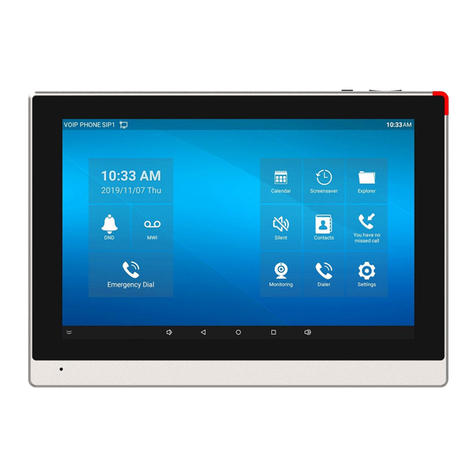
Fanvil i51W is a 4.3-inch indoor station and i52W is a 7-inch indoor station, which support 8-way alarm
input and industrial power socket input interface. It is mainly used in residential areas, villas, office buildings
and other places to receive calls from the door phone, and communicate with the door phone, and achieve the
remote access control. It provides reliable security and convenient access to door control, creating a safe and
comfortable living environment for the majority of users.
To help the users better understand the product details, this user manual can be used as a reference guide for
i51W&i52W. This document may not be applicable to the latest version of the software. If you have any
questions, you can use the i51W&i52W device's built-in help tips interface, or download and update your
user manual from the Official Fanvil website.
3.2 Product Introduction
Table 1 – Model Configuration
Model
Configuration
i51W
4.3-inch display,Support WiFi、RS-485
i52W
7-inch display,Support WiFi、RS-485

7
4Install Guide
4.1 Use PoE or external Power Adapter
i51W&i52W, called as ‘the device’ hereafter, supports two power supply modes, power supply from external
power adapter or over Ethernet (PoE) complied switch.
PoE power supply saves the space and cost of providing the device additional power outlet. With a PoE
switch, the device can be powered through a single Ethernet cable which is also used for data transmission.
By attaching UPS system to PoE switch, the device can keep working at power outage just like traditional
PSTN telephone which is powered by the telephone line.
For users who do not have PoE equipment, the traditional power adaptor should be used. If the device is
connected to a PoE switch and power adapter at the same time, the power adapter will be used in priority and
will switch to PoE power supply once it fails.
Please use the power adapter supplied by Fanvil and the PoE switch met the specifications to ensure the
device work properly.

8
5Appendix Table
5.1 Appendix I - Icon
Table 2 - Keypad Icons
Speed Dial
Live View
Open Door
Return/End
Answer
Table 3- Status Prompt and Notification Icons
Call out
Call in
Network Disconnected
Auto-answering activated
The Voice quality of calling
The Voice encryption of calling
Connecting WIFI
Open SIP Hotspot

9
6Introduction to the User
6.1 Instruction of Keypad
Picture 1 – Key Instruction
The image above shows the device's key layout. Each key provides its own specific function. The user may
refer to the key instructions in the illustrations in this section to operate the device.
Some keys can be long pressed. Users can hold down the button for 3 seconds to trigger the function.
Table 4 - Key Instruction
Key
Index
Key Name
Description
1
Management
Center
One press to call out the set number. If not set, press down and
the pop-up prompts
2
Video
Monitoring
One press to check the outdoor situation. If not set, press down
and the pop-up prompts
3
Unlock Key
One press to unlock the door. Press 3s to enter the menu
interface.
4
Return Key
Hang up when making a call
Other manuals for i51W
2
This manual suits for next models
1
Table of contents
Other Fanvil Intercom System manuals
Fanvil
Fanvil i16S User manual
Fanvil
Fanvil i10 User manual
Fanvil
Fanvil i51W User manual
Fanvil
Fanvil i12 User manual
Fanvil
Fanvil i23 User manual

Fanvil
Fanvil i10 User manual
Fanvil
Fanvil i30 User manual
Fanvil
Fanvil i10V Installation and user guide
Fanvil
Fanvil i12-01 User manual
Fanvil
Fanvil i33V User manual
