Fasep VIDEOTRONIC V653.G2 User manual

Fasep 2000 srl Rev. 1.3
Videotronic V653.G2: User’s Manual 02 april 2010
For any information, please contact: www.fasep.it
e-mail: [email protected]
FASEP 2000 srl
Via Faentina 96
50032 Ronta (Fi) Italy
Tel. #39 055 840 3126
Fax #39 055 840 3354 i
VIDEOTRONIC V653.G2
USER’S MANUAL

Fasep 2000 srl Rev. 1.3
Videotronic V653.G2: User’s Manual 02 april 2010
ii
WARNING
.This document contains information which is the property of FASEP 2000 rl and all rights are reserved. This manual shall not be
photocopied or reproduced in any way without the prior written consent of FASEP 2000 srl.
.FASEP 2000 srl reserves the right to revise products firmware, software or documentation without obligation to notify any person
or organization. The information contained in this document is subject to change without warning.
.Prior of the installation of the unit described in this manual, user should read this manual carefully to be instructed properly on
installation, use and maintenance of the unit.
.Failing to read this manual and operate accordingly may cause damage to the user or the unit.
.FASEP 2000 srl shall not be responsible for inconvenience, breakdown, accidents due to uncomplete knowledge of this manual
or uncomplete application of raccomendations described in this manual.
.FASP2000srlshallnotberesponsibleforinconvenience, breakdown, accidentsduetounauthorizedmodifications of the unit, use
ofnon-original or unauthorizedaccessories(see Accessories listingin this manual for alist oforiginal accessories available forthis
model).
.FASEP2000 srl shall not beresponsible for any inconvenience,breakdown, accidents caused directlyor indirectlyby not
qualified service. Service to any parts by not qualified persons will void warranty and will void any right of the owner of
the unit.
SYMBOLS AND CONVENTIONS
To speed the retrieval of main information and make easy to understand the instructions, this manual uses the following typing
conventions:
<NAME OF THE PUSH BUTTON> Used to indicate name of push-buttons on the control panel.
DISPLAY Used to indicate text or number visible on the displays on the control panel.
☺ADVICES Contain useful advices or solutions, evidence d with respect to the rest of the text.
NOTE Notes contain important information, evidenced to the rest of the text.
WARNING Warning messages appears corresponding to procedures that, if not properly observed,
may lead to loose of data or cause damage to the unit.
!CAUTION Caution messages appears corresponding to procedures that, if not properly observed,
may cause injuries to the user.

Fasep 2000 srl Rev. 1.3
Videotronic V653.G2: User’s Manual 02 april 2010
iii
ORIGINAL INSTRUCTIONS
TABLE OF CONTENTS
WARNING .......................................................................................... ii
SYMBOLSANDCONVENTIONS ........................................................................ ii
1 PRESENTATION ............................................................................1-1
1.0 Intended Use .......................................................................1-1
1.1 Definitions .........................................................................1-1
2 INSTALLATION .............................................................................2-1
2.1 Movingtheunit......................................................................2-1
2.2 Assemblingtheunit ..................................................................2-1
2.3 Installation .........................................................................2-1
2.4 ElectricalHookup....................................................................2-1
2.5 Compressed air Hookup (PL models only) ................................................2-1
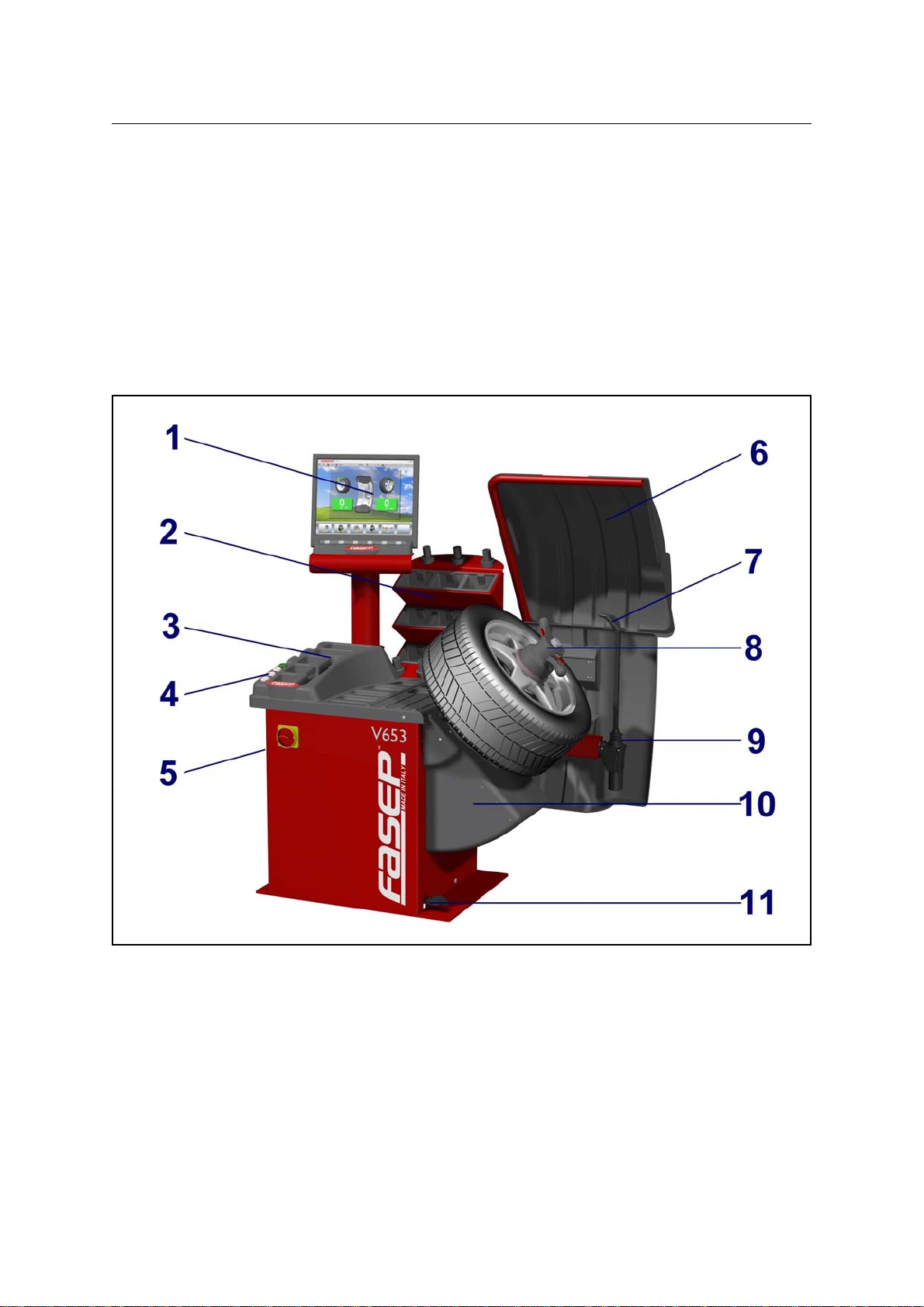
3 USEOFCONTROLPANEL....................................................................2-2
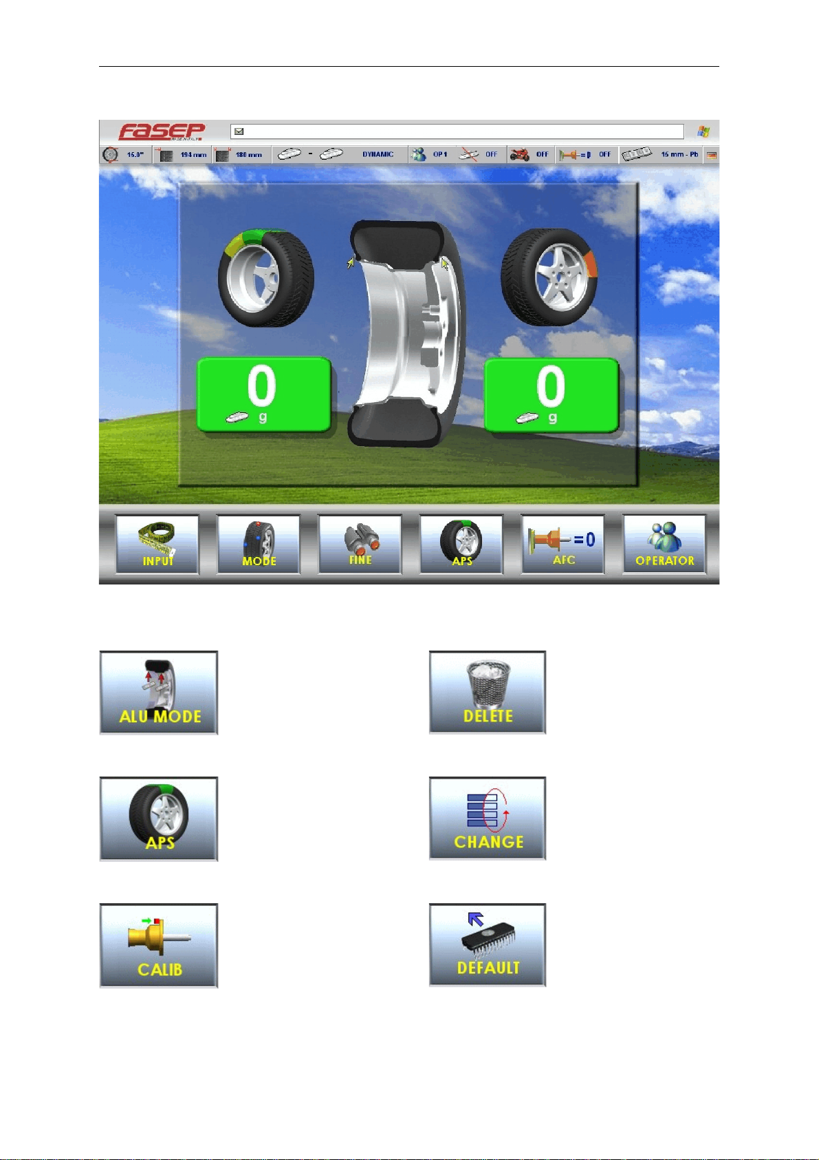
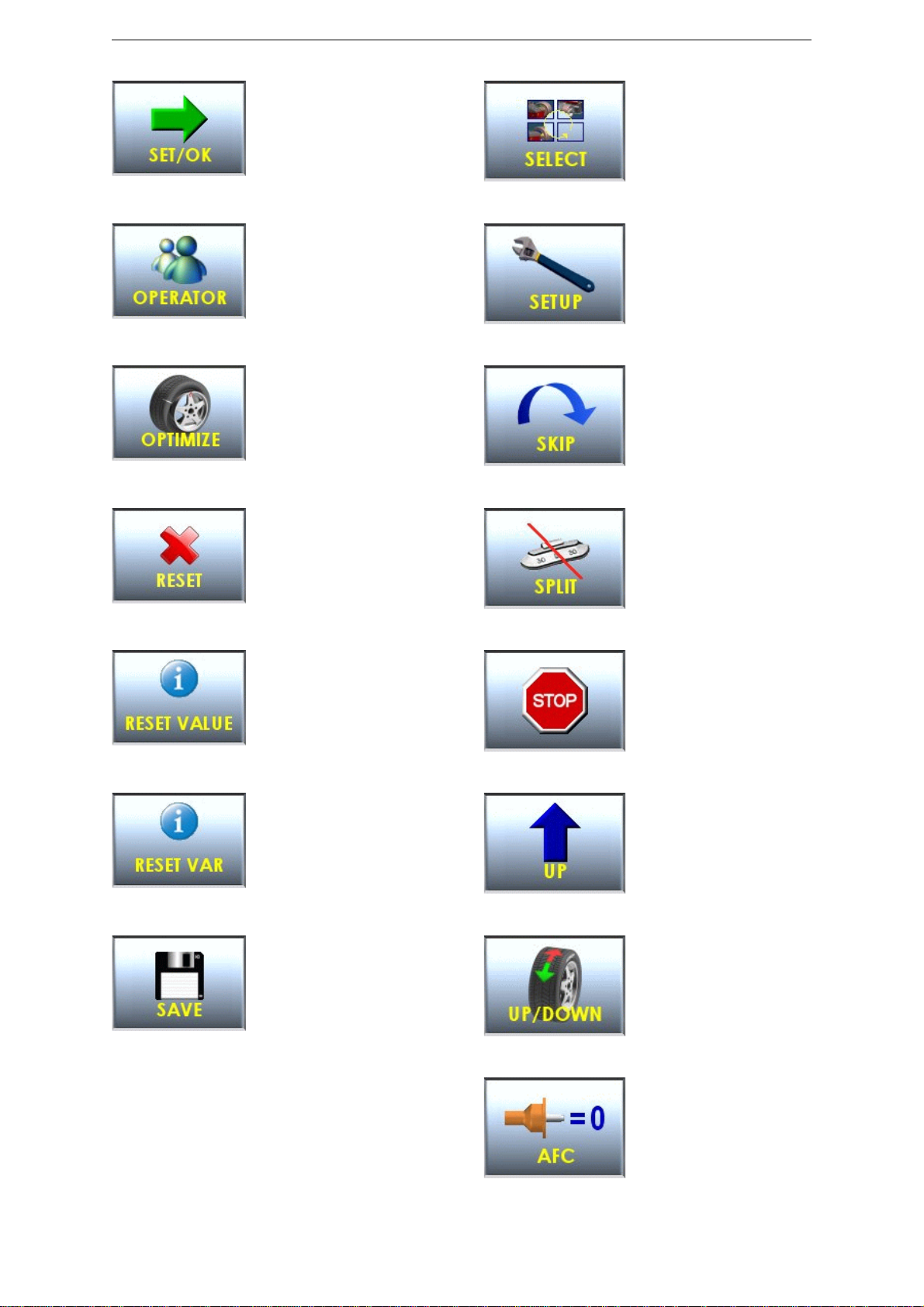
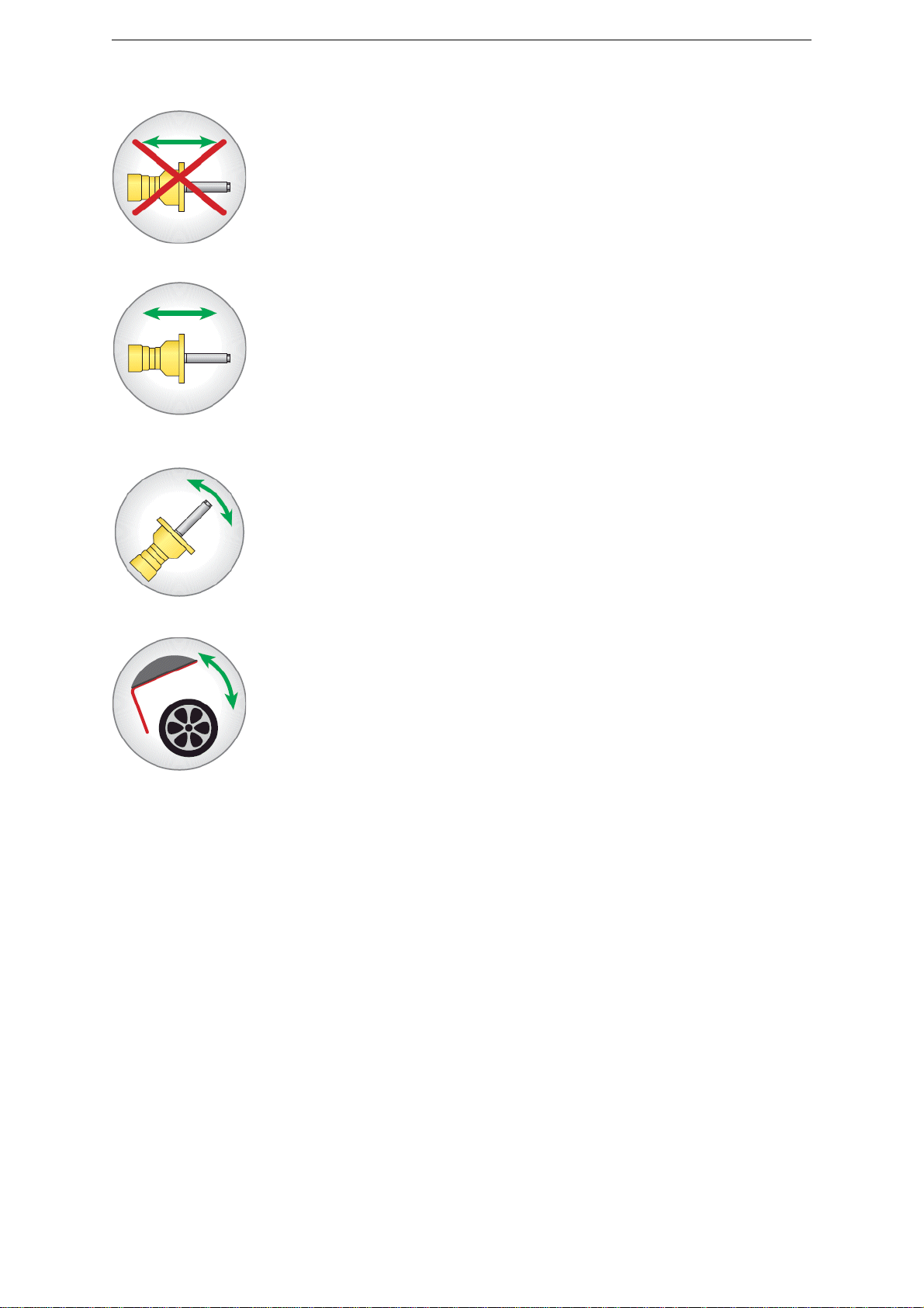
3.1 Meaning of the icons on the screen ......................................................2-2
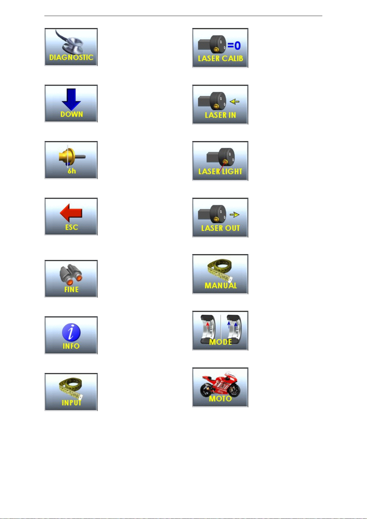
3.2 Meaning of the command keys .........................................................3-1
4 CALIBRATIONOFWHEELBALANCER..........................................................3-1
4.1 How to calibrate the wheel balancer .....................................................3-1
4.2 How to control the calibration of wheel balancer and position weight ............................3-2
5 CalibrationALU-SE ..........................................................................4-1
6 CalibrationSME .............................................................................4-2
7 MEASUREMENTANDCORRECTIONOFUMBALANCE ............................................4-3
7.1 Placing the wheel rim on the wheel balancer ...............................................4-3
7.2 Input of Rim Dimensions (external measuring system version) .................................4-3
7.3 Input of Rim Dimensions (ALU-SE or LASER version) .......................................4-4
7.4 Detecting and correcting umbalance .....................................................4-4
7.5 How to apply the weight using ALU-SE applicator ...........................................4-5
7.6 How to apply the weight using LASER ....................................................4-5
7.7 HowtouseSPLITProgram ............................................................4-5
8 HOWTOOPTIMIZEUNBALANCEOFTHEWHEEL ................................................5-1
9 SPECIAL FUNCTIONS .......................................................................6-1
9.1 Language selection ..................................................................6-1
9.2 Setup .............................................................................6-1
9.3 Personalization .....................................................................6-1
9.4 Run-outcheckprogram ...............................................................6-1
APPENDIX ........................................................................................ A-2
A: Technicaldata ..................................................................... A-2
B: Environmental Data, Safety Features and Requirements .................................... B-1
C: Errors and Malfunctions recognized by the Computer ....................................... B-4
D: How to remove the battery from the product safely. ........................................ B-5

Fasep 2000 srl Rev. 1.3
Videotronic V653.G2: User’s Manual 02 april 2010
1-1
1 PRESENTATION
1.0 Intended Use
This unit is designed to measure and correct static and dynamic unbalance of vehicle wheel, the dimension and weight
of which are within the working range of the machine (see “Technical Data”appendix for reference)
This unit is meant for a professional use. Operator shall be properly trained before use. Training Course is not included
in the price of the unit and must be purchased separately.
This unit is designed for indoor use only (see “Environmental Data”appendix for reference).
!CAUTION: This unit is designed to spin vehicle wheels only, within the range of dimensions and weight
approved (see “Technical Data”appendix for reference). Special adaptors suit this purpose. Do not
attempt to use the machine to spin anything else. Unproper locking may cause the part being
spinned to be ejected, causing damage to the unit itself, the operator or anything in the in the
neighboorhood.
1.1 Definitions
1. Monitor
2. Back-mounted weight-compartments
3. Weights and tools trays
4. Interface icons + buttons
5. Side flange-holders
6. Wheel guard
7. EMS External Measuring system
8. Quick lock + HD shaft
9. Lower wheel guard
10. Tilt-system
11. Foot-pedal electro-magnetic brake

Fasep 2000 srl Rev. 1.3
Videotronic V653.G2: User’s Manual 02 april 2010
2-1
2 INSTALLATION
2.1 Moving the unit
WARNING When the unit has to be moved: never lift
balancerbymotorshaft or byneighborhoodofit.
2.2 Assembling the unit
Foreaseoftransportation,thewheelbalancermightbedisassembled
into units. If necessary, assembling instruction are provided within
each package..
2.3 Installation
The wheel balancer must be installed on a firm and level ground.
NOTE:the machine must be secured to the floor. Using four holes
in the base and anchor bolts provided
2.4 Electrical Hookup
!CAUTION: Failure to follow these instructions can results in
damage to unit or create an electrical hazard and
will void warranty..
2.4.1 Electrical hookup is to be provided by a qualified electrician.
2.4.2 Afusiblewall-mountedswitchboxisrequiredattheinstallationsite.Thisswitchshouldprovideon-offcontrolandoverload
protection for your wheel balancer only. The switchbox should be fused with time-delay fuse(s) in accordance with the
power rating specified on your wheel balancer.
2.4.3 Electrical connection of the machine should be by plug connectors.
2.4.4 The balancer must be effectively connected to ground. The electric cord is regularly provided with a ground terminal.
2.4.5 Make sure that Power Rate Specifications for your wheel balancer (refer to nameplate on the wheel balancer) comply
with those provided by the external power source.
!CAUTION Afterelectricalhookuphasbeenperformedunitisreadytooperate. Alwaysobservepertinentsafety
precautions when operating the unit (see Appendix tables for an overview of relevant Safety
requirement).
2.5 Compressed air Hookup (PL models only)
!CAUTION Failure to follow these instructions can result in damage to unit or create a hazard and will void
warranty.
1. Compressed Air hookup is to be provided by a qualified technician, under the local safety
requirements, in line with relevant national standards and regulations. All fitting and hoses must
conform to local codes.
2. A wall-mounted lubricator and water-separator is required at the installation site.
3. Compressed Air circuit to the balancer shall be regulated to a maximum pressure of 7 atm.
Overpressure could compromise cylinder operation.
2.5.1 CONNECT TO AIR SUPPLY:
The machine is fitted with a universal connector and therefore no other special or additional fitting is required. Push all
the way onto the connector a high pressure rubber air-hose and secure it.

Fasep 2000 srl Rev. 1.3
Videotronic V653.G2: User’s Manual 02 april 2010
2-2
3 USE OF CONTROL PANEL
3.1 Meaning of the icons on the screen
Select balancing mode
APS Function
Calibration
Delete last character in input
activation code
Change selection
Set default values
Fig. 5 Panel V653
Fig. 6
Fig. 7
Fig. 8
Fig. 9
Fig. 10
Fig. 11

Fasep 2000 srl Rev. 1.3
Videotronic V653.G2: User’s Manual 02 april 2010
2-3
Diagnostic
Key down
Position calibration
Go to previous page
Fine resolution
Access to Information center
Access to page measures
Laser calibration
Put in the rod laser in rest
position
Start laser
Extract fully rod laser
Manul input measures
Set Dynamic/Static
Mode moto
Fig. 12
Fig. 13
Fig. 14
Fig. 15
Fig. 16
Fig. 17
Fig. 18
Fig. 19
Fig. 20
Fig. 21
Fig. 22
Fig. 23
Fig. 24
Fig. 25

Fasep 2000 srl Rev. 1.3
Videotronic V653.G2: User’s Manual 02 april 2010
2-4
Key SET/OK
Double operator
Optimize
Restart software
Reset partial statistics
Reset variation in page Sensor
Save
Set measures
Go to setup menù
Skip current operation
Split function
Stop turning wheel
Key up
View menù and selection
(UP/DOWN
Automatic flange calibration
Fig. 26
Fig. 27
Fig. 28
Fig. 29
Fig. 30
Fig. 31
Fig. 32
Fig. 33
Fig. 34
Fig. 35
Fig. 36
Fig. 37
Fig. 38
Fig. 39
Fig. 40

Fasep 2000 srl Rev. 1.3
Videotronic V653.G2: User’s Manual 02 april 2010
2-5
3.2 Meaning of the command keys
Disable open pneumatic lock (safety for flange use)
Open / close pneumatic lock
Tilting
Open / close wheel guard
Fig. 41
Fig. 42
Fig. 43
Fig. 44

Fasep 2000 srl Rev. 1.3
Videotronic V653.G2: User’s Manual 02 april 2010
3-1
Fig. 45
Fig. 46
Fig. 47
Fig. 48
4 CALIBRATION OF WHEEL BALANCER
4.1 How to calibrate the wheel balancer
NOTE:the following symptoms indicate need for calibration::
a) check calibration program fails. b) constant low or high weight readings.
c) indicated point of unbalance constantly wrong d) more than 2 spins required to balance wheels
repeatedly.
Switch on the wheel balancer.
Select SET UP > CALIBRATION > SET/OK >
CALIBRATION > SET/OK.
Spin with no wheel on shaft (Fig. 46)
Close the wheel guard or press <START>.
At the end of the spin, put a wheel (Fig. 47)
and close the wheel guard or press <START>.
At the end of the spin, put the calibration
weight (Fig. 48) and close the wheel guard or
press <START>.

Fasep 2000 srl Rev. 1.3
Videotronic V653.G2: User’s Manual 02 april 2010
3-2
Fig. 49
4.2 How to control the calibration of wheel balancer and position weight
Switch on the wheel balancer.
Select SET UP > CALIBRATION > SET/OK >
CHECK CALIBRATION > SET/OK.
Put a wheel on the shaft and press <START>
(Fig50).
Put the calibration weight (Fig.51) and press
<SET/OK>.
Close the wheel guard or press <START>.
At the end of the spin, 160-0 will show on the
video (tolerance allowed is ±10).
Put the weight at 6h o’clock: the weight
indicators of internal side must be both green.
If not, press <6h>.
Put the weight at 6h o’clock and press <SET
OK>.
Fig. 50
Fig. 51
Fig. 52

Fasep 2000 srl Rev. 1.3
Videotronic V653.G2: User’s Manual 02 april 2010
4-1
5 Calibration ALU-SE
Switch on the wheel balancer.
MAIN MENU > MENU > RESET > CALIB > ALU-SE
CALIBRATION > SET/OK (fig. 53).
Put the rod on rest position (fig.53) and press SET/ OK.
Put the rod on the flange (fig.54) and press SET/ OK.
Select width of wheel
Put the rod on internal side of the rim (fig.55) and press
SET/OK.
Press <ESC> to go back to standard use.
Fig. 53
Fig. 54
Fig. 55

Fasep 2000 srl Rev. 1.3
Videotronic V653.G2: User’s Manual 02 april 2010
4-2
6 Calibration SME
Switch on the wheel balancer.
MAIN MENU > MENU > RESET > CALIB > SME
CALIBRATION > SET/OK (fig. 56)
Put the rod on rest position (fig. 56) and press SET/ OK.
Put the rod (fig. 57) and press SET/OK.
Press <ESC> to go back to standard use.
Fig. 56
Fig. 57

Fasep 2000 srl Rev. 1.3
Videotronic V653.G2: User’s Manual 02 april 2010
4-3
Fig. 59: Distance
Fig. 60: Width
7 MEASUREMENT AND CORRECTION OF UMBALANCE
7.1 Placing the wheel rim on the wheel balancer
7.1.1 Select the cone or flange suitable for the wheel to be balanced. Specific mounting instructions are delivered with each
flange
NOTE: the operation of centering and tightening of the wheel on the flanges is of basic importance for correct
balancing. Good results depend on proper performance of these procedures.
To accurately clean up the superficial ones of connection before whichever operation.
!CAUTION: Always make sure flanges are correctly locked on the motor shaft and wheel is correctly locked on
the flange being used.
7.2 Input of Rim Dimensions (external measuring system version)
for V65x, V64x, V55x-D (automatic input of all data)
MAIN MENU > INPUT
Insert the distance (fig.59).
Insert the width (fig.60).

Fasep 2000 srl Rev. 1.3
Videotronic V653.G2: User’s Manual 02 april 2010
4-4
Fig. 61
Fig. 62
7.3 Input of Rim Dimensions (ALU-SE or LASER version)
!CAUTION: Laser installed on wheel balancer is of class 2, so special protection are not required. It is however
recommended to avoid the continuos view of the direct beam.
MAIN MENU > INPUT
Press ALU MODE untill the required position of weight is on the video (fig.61).
Insert the distance (IN1).
Insert the distance (IN2).
Press ALU MODE untill the required position of weight is on the video (fig.61).
Insert the distance (IN1).
Insert the distance (IN2).
7.4 Detecting and correcting umbalance
7.4.1 After setting wheel dimensions, press <START> or close the safety cover to spin the wheel and start the measurement
run.
!CAUTION: wheel start automatically when safety cover is closed.
7.4.2 At the end of the spin the wheel will brake automatically and the display will show the weight position and weight
requirement to correct the wheel’s umbalance.
7.4.3 Apply the weights (fig.63, fig.64). If umbalance shown is 0, press <FINE> to show residual umbalance.
Fig. 63 Fig. 64

Fasep 2000 srl Rev. 1.3
Videotronic V653.G2: User’s Manual 02 april 2010
4-5
Fig. 65
Fig. 68 Fig. 69
7.5 How to apply the weight using ALU-SE applicator
Place the weight as in the picture 66.
Turn the wheel until reach the application
position of the weight (fig. 65).
Move the rod until reach the application
position of the weight (fig. 66).
Apply the weight (fig. 67).
Repeat the procedure for the other side.
.
7.6 How to apply the weight using LASER
Turn the wheel until the position weight
indicators of one side are both green (fig. 68).
The laser come out to show the point of
application of the weight (fig. 69).
Apply the weight on the laser dot.
Repeat the procedure for the other side.
7.7 How to use SPLIT Program
After the measurement spin
Press <SPLIT> to select the program.
Turn the wheel until first spoke (green position) is at 12 0' clock.
Press <SET/OK> to confirm.
Turn the wheel until second spoke (red position) is at 12 o’ clock
Press <SET/OK> to confirm the red position.
Balance the wheel applying weight on green and red positions.
Fig. 66
Fig. 67

Fasep 2000 srl Rev. 1.3
Videotronic V653.G2: User’s Manual 02 april 2010
5-1
8 HOW TO OPTIMIZE UNBALANCE OF THE WHEEL
8.1.1 MAIN MENU > OPTIMIZE
Measure the unbalance of the rim only ( fig. 70).
Mount the tire on the rim and put the wheel on the shaft
(fig.71).
Spin the wheel
Select the optimization and follow the video instruction.
WARNING:Balancing with flanges, put the accessories assembled to the rim during the complete operations.
NOTE:Selection of optimization: the green solution is the advised from the machine. The user can be choose also
one of the other.
Fig. 70 first spin, rim only
Fig. 71 second spin, complete wheel

Fasep 2000 srl Rev. 1.3
Videotronic V653.G2: User’s Manual 02 april 2010
6-1
9 SPECIAL FUNCTIONS
9.1 Language selection
9.1.1 MAIN MENU >SET UP > USER SET UP > LANGUAGE > SET OK >.
9.1.2 Select the language and press SET OK.
9.2 Setup
9.2.1 MAIN MENU >SET UP > USER SET UP .
9.2.2 Select item and press SET OK.
9.3 Personalization
9.3.1 MAIN MENU > PERSONAL.
9.3.2 Follow the instruction on video to insert the personalization.
9.3.3 Press SAVE to memorize.
9.4 Run-out check program
9.4.1 Insert the wheel dimensions.
9.4.2 MENU > RUNOUT.
9.4.3 Put the rod (fig. 72) and turn slowly the wheel for 360/.
Fig. 72 Runout

Fasep 2000 srl Rev. 1.3
Videotronic V653.G2: User’s Manual 02 april 2010
A-2
Fig. 73: Measures
APPENDIX
A: Technical data
Power requirement 400W
Speed Balancing 98RPM
Measuring time 4-15 s.
Accuracy ±1grammo (±1/28 once)
Wheel Dimensions Diameter Rim diameter 8" (200 mm) - 26" (650 mm)
Rim Width (with wheel-guard) max 16" (415mm)
Wheel Weight max 90 Kg (198Lbs)
Wheel balancer dimensions
V653
L (mm) 1120
L1 (mm) 500
L2 (mm) 1230
P (mm) 1030
P1 (mm) 200
P2 (mm) 1450
H (mm) 1390
H1 (mm) 1440
Peso (kg) 167

Fasep 2000 srl Rev. 1.3
Videotronic V653.G2: User’s Manual 02 april 2010
B-1
B: Environmental Data, Safety Features and Requirements
Environmental Data
[Operating conditions]
This unit is designed for indoor use only.
Temperature: 0 to 45/C
Relative Humidity: 5 to 80% a 40/
[Storage conditions]
Package is designed for indoor storage only.
Temperature: -25/to 70/C
Relative humidity: 5 at 95% to40/C
Safety Features
1. TheBalanceWeightsHolder mayberemovedforservicing.It issecuredtothemachinebodythroughscrewssothatonly
voluntarily it may be removed. Removal of this protection is therefore restricted to Authorized Service Engineers.
2. TheControlPanelmayberemoved forservicing.Itissecuredtothemachinebodythroughscrewssothatonlyvoluntarily
it may be removed. Removal of this protection is therefore restricted to Authorized Service Engineers.
!CAUTION: The safety cover is anyway required when using the motorcycle adapter.
WARNING FASEP 2000 srl shall not be responsible for any inconvenience, breakdown, accidents caused
directlyorindirectlybyunauthorizedservice.Servicetoanypartsbyunauthorizedengineerswillvoid
warranty and will any right of the owner of the unit..
NOTE: As this unit runs at speed below 100rpm, a safety cover is not required. However a safety cover is
recomended when balancing wheels with diameter bigger then 20".
General Safety Requirement
[before using/servicing this unit]
1. Read this instruction sheet and the whole user’s manual before operating or servicing the wheel balancer.
2. Make sure electrical power source conforms to requirements shown on nameplate (see also model identification chart
for reference).
3. Make sure the unit has a stable position.
[when using the unit]
4. Protect power leading to the unit from damage.
5. When work area is being washed, make sure unit is adequately protected.
6. Remove all stones and mud lodged in tire treads before balancing the wheel.
7. Do not touch spinning wheel. Always use Safety Safety cover to be protected.
8. Make sure counterweights are securely attached before checking residual umbalance.
[when servicing the unit]
9. Make sure power sources are disconnected before service on the unit is performed.
10. Service to PCB, electrical and mechanical parts should be done only by an Authorized FASEP 2000 Service Center.
Table of contents
Other Fasep Wheel Balancer manuals

Fasep
Fasep B350.G3 User manual

Fasep
Fasep B222 User manual

Fasep
Fasep BALATRON B110 User manual

Fasep
Fasep RGU 56 XL Operation instructions

Fasep
Fasep BALATRON B150 User manual

Fasep
Fasep VIDEOTRONIC V644.G3 User manual

Fasep
Fasep VIDEOTRONIC V548.G4 User manual

Fasep
Fasep VIDEOTRONIC V788.G3 User manual

Fasep
Fasep VIDEOTRONIC V688.G3 User manual
Popular Wheel Balancer manuals by other brands

HENNESSY INDUSTRIES
HENNESSY INDUSTRIES Coats 885 Safety Instructions, Set Up Instructions, Operation Instructions, Maintenance Instructions

pela tools
pela tools U-800 manual

Sun Microsystems
Sun Microsystems SWB 300 Operator's manual

Cormach
Cormach TOUCH MEC 100 Use and maintenance manual

Coseng
Coseng SP711N Operation manual

BRIGHT
BRIGHT VULTURE BP46 manual