Fasep 2000 srl Rev. 1.0
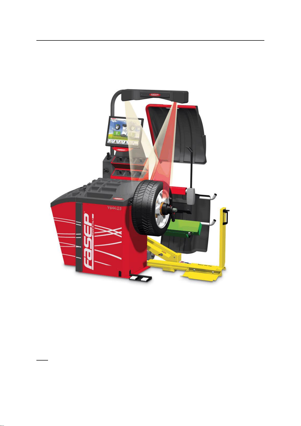
Videotronic V644.G3: User’s Manual 27 november 2013
iii
ORIGINAL INSTRUCTIONS
TABLE OF CONTENTS
WARNING ............................................................................................. ii
SYMBOLSANDCONVENTIONS........................................................................... ii
1 PRESENTATION ............................................................................. 1-1
1.0 IntendedUse......................................................................... 1-1
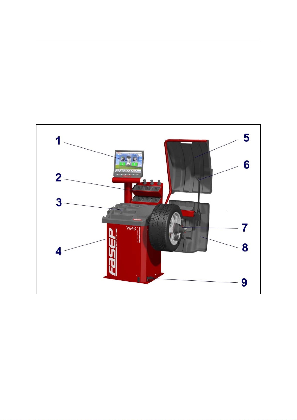
1.1 Definitions ........................................................................... 1-1
2 INSTALLATION............................................................................... 2-1
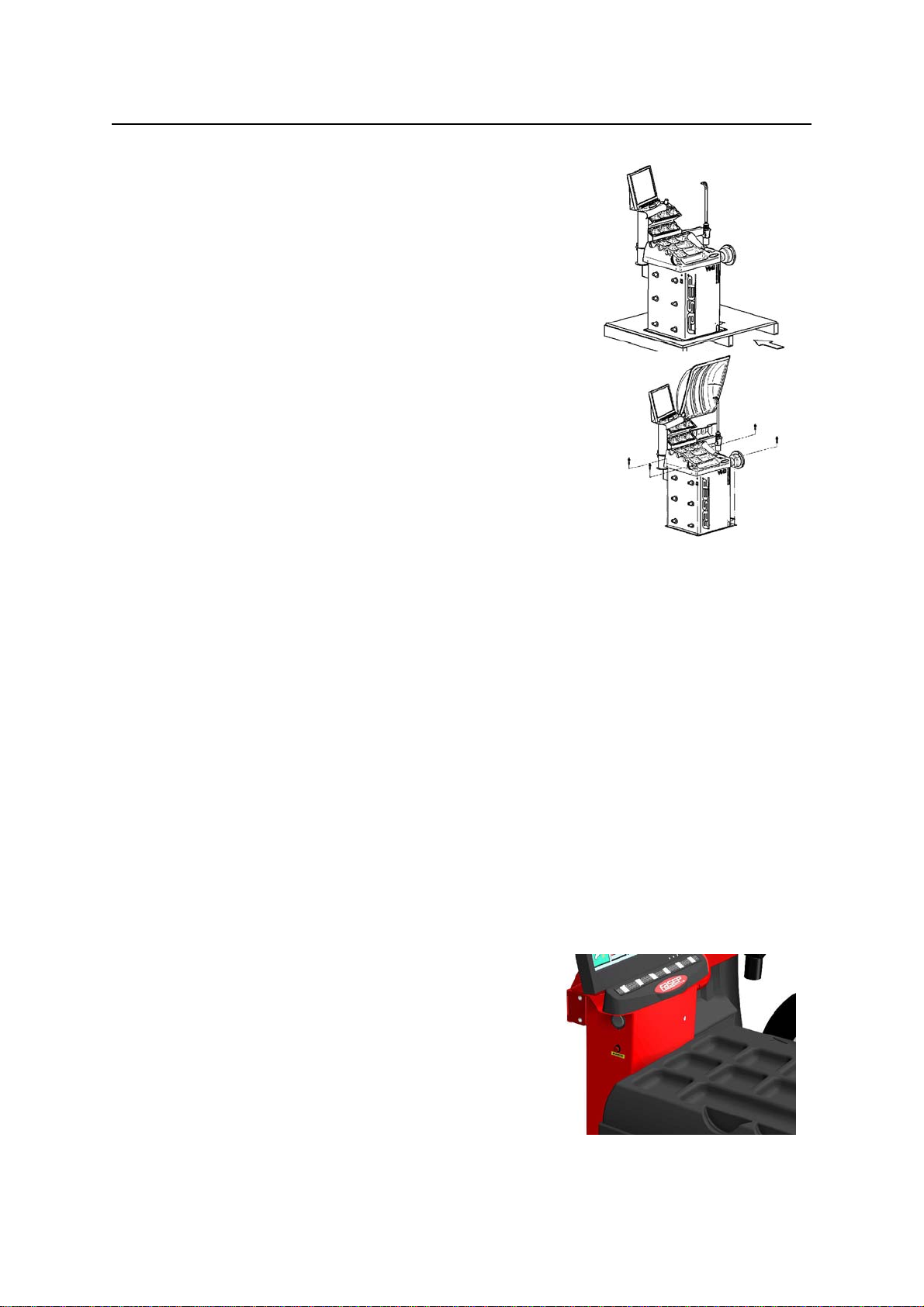
2.1 Movingtheunit ....................................................................... 2-1
2.2 Assemblingtheunit.................................................................... 2-1
2.3 Installation ........................................................................... 2-1
2.4 ElectricalHookup ..................................................................... 2-1
2.5 CompressedairHookup(PLmodelsonly) .................................................. 2-1
2.6 Power .............................................................................. 2-1
3 USEOFCONTROLPANEL..................................................................... 2-2
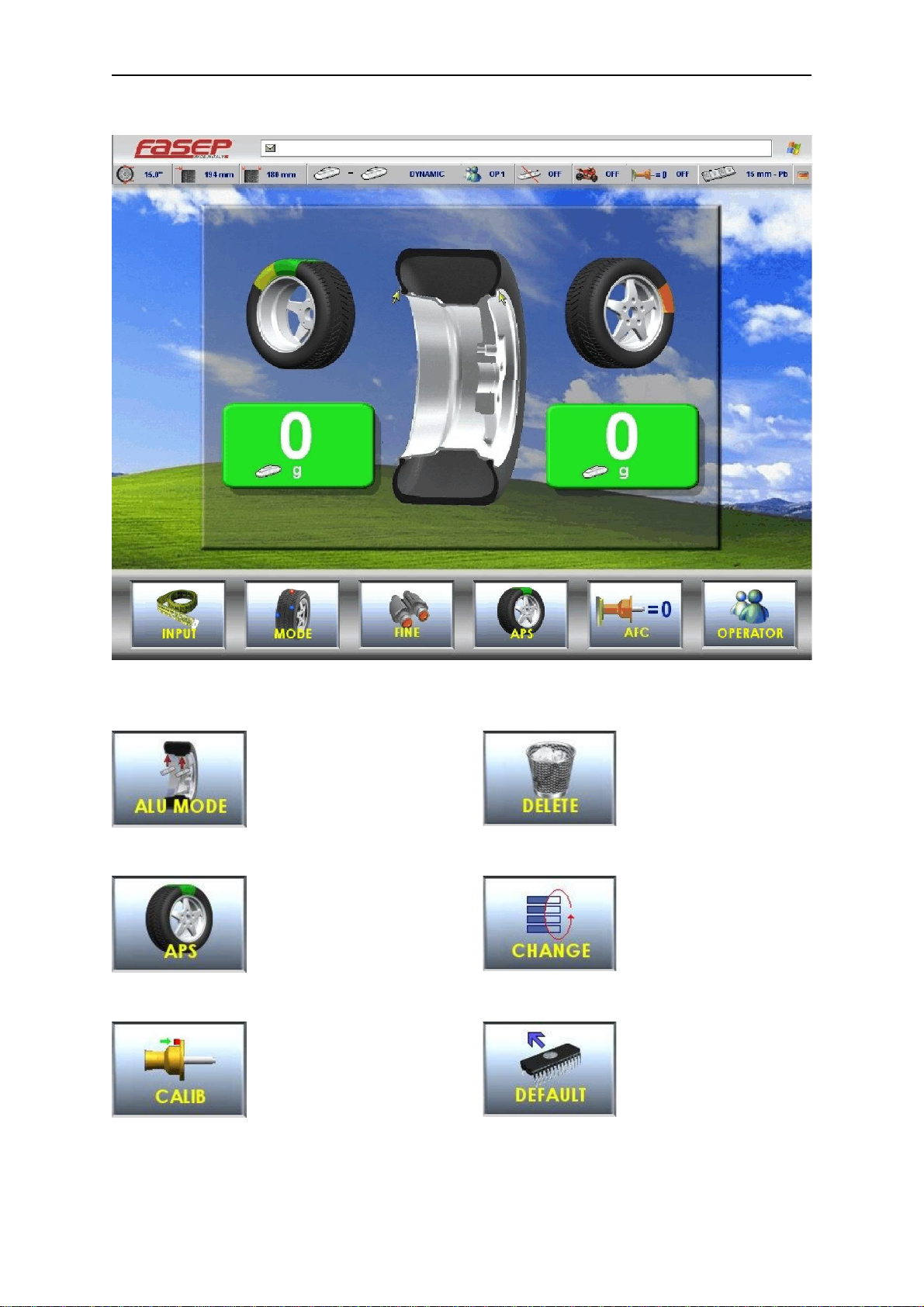
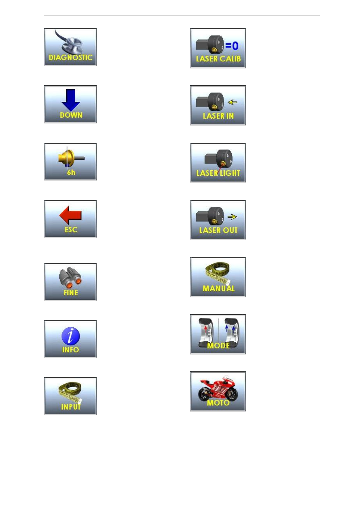
3.1 Meaningoftheiconsonthescreen........................................................ 2-2
4.0 CALIBRATIONOFWHEELBALANCER........................................................... 2-5
4.1 Howtocalibratethewheelbalancer ....................................................... 2-5
4.2 How tocontrol the calibration of wheel balancer and position weight . . . . . . . . . . . . . . . . . . . . . . . . . . . . . . . 2-6
5 CalibrationALU-SE ............................................................................ 3-5
6 CalibrationSME............................................................................... 3-6
7 MEASUREMENT AND CORRECTION OF UMBALANCE . . . . . . . . . . . . . . . . . . . . . . . . . . . . . . . . . . . . . . . . . . . . . 3-7
7.1 Placing the wheel rim on the wheel balancer . . . . . . . . . . . . . . . . . . . . . . . . . . . . . . . . . . . . . . . . . . . . . . . . . 3-7
7.2 Input of Rim Dimensions (external measuring system version) . . . . . . . . . . . . . . . . . . . . . . . . . . . . . . . . . . . 3-7
7.3 Input of Rim Dimensions (ALU-SE or LASER version) . . . . . . . . . . . . . . . . . . . . . . . . . . . . . . . . . . . . . . . . . 3-8
7.4 Detectingandcorrectingumbalance....................................................... 3-8
7.5 How toapply the weight using ALU-SE applicator . . . . . . . . . . . . . . . . . . . . . . . . . . . . . . . . . . . . . . . . . . . . . 3-9
7.6 HowtoapplytheweightusingLASER ..................................................... 3-9
7.7 HowtouseSPLITProgram.............................................................. 3-9
8 HOWTOOPTIMIZEUNBALANCEOFTHEWHEEL................................................. 4-1
9 SPECIALFUNCTIONS......................................................................... 5-1
9.1 Languageselection .................................................................... 5-1
9.2 Setup............................................................................... 5-1
APPENDIX........................................................................................... A-2
A: Technicaldata........................................................................ A-2
B: Environmental Data, Safety Features and Requirements . . . . . . . . . . . . . . . . . . . . . . . . . . . . . . . . . . . . . . . B-1
C: Errors and Malfunctions recognized by the Computer . . . . . . . . . . . . . . . . . . . . . . . . . . . . . . . . . . . . . . . . . . B-2
D: How toremove thebattery from the product safely. . . . . . . . . . . . . . . . . . . . . . . . . . . . . . . . . . . . . . . . . . . . . B-3