manuals.online logo
Brands
  1. Home
  2. •
  3. Brands
  4. •
  5. Festo
  6. •
  7. Control Unit
  8. •
  9. Festo EHMD-40-RE Series User manual

Festo EHMD-40-RE Series User manual

Translation of the original instructions
1 About this document
1.1 Applicable documents
All available documents for the product èwww.festo.com/pk.
Identifier Contents
Application note Application examples for connection and com
missioning
Tab. 1 Documentation for rotary gripper module
2 Safety
2.1 General safety instructions
– Only use the product in original status without unauthorised modifications.
– Only use the product if it is in perfect technical condition.
– Observe labelling on the product.
– Store the product in a cool, dry, UVprotected and corrosionprotected envir
onment. Ensure that storage times are kept to a minimum.
– Prior to mounting, installation and maintenance work: Switch off power sup
ply and secure it from being switched back on.
– Observe tightening torques. Unless otherwise specified, the tolerance
is±20%.
2.2 Intended use
The intended use of the product is to grip, hold and rotate payloads (workpieces).
2.3 Foreseeable misuse
Gripping where the point of application is on the inside is not intended.
EHMD...GE: In normal operation, hitting the stop when moving in the opening
direction is not intended.
2.4 Training of qualified personnel
Only qualified personnel may perform installation, commissioning, maintenance
and disassembly of the product.
The qualified personnel must be familiar with the installation and operation of
electrical and pneumatic control systems.
3 Additional information
– Accessories èwww.festo.com/catalogue.
4 Service
Contact your regional Festo contact person if you have technical questions
èwww.festo.com.
5 Product overview
5.1 Functional principle
Fig. 1 Functional principle
The product is a combined rotating and gripping module. Gripping occurs in the
closing direction of the gripper jaws (point of application on the outside).
The parallel gripper can be actuated electrically (EHMD...GE) or pneumatically
(EHMD...GP), depending on version.
In both versions, the parallel gripper can be continuously rotated by means of the
electric axis of rotation.
Gripping force backup
EHMD...GP: without gripping force backup. Backup for the gripping force can
only be ensured using additional measures (e.g. uninterruptible compressed air
supply).
EHMD...GE: with gripping force backup. If the power supply is interrupted, a min
imum gripping force is ensured by the mechanical design. However, the maximum
gripping force cannot be maintained.
5.2 Product design
EHMD-40-RE-GE|EHMD-40-RE-GP|EHMD-40-RE-GE-16
1Stepper motor for the gripper func
tion (installed in the housing)
2Warning  hot surface
3Pneumatic cylinder for gripper
function
4Rotatable gripper module
5Gripper jaw
6Product labelling
Fig. 2 Product design
6 Mounting
6.1 Mounting the gripper fingers (EHMD-40-RE-GE/-GP)
1Screw
2Centring sleeve
3Gripper jaw
4Gripper jaw blank (not in scope of
delivery)
Fig. 3 Mounting the gripper fingers
1. Press centring sleeves 2 into locating holes in the gripper jaws 3.
2. Apply mediumstrength screw locking agent to socket head screws 1.
3. Position gripper fingers 4 on the gripper jaws 3.
4. Screw in socket head screws 1. Comply with the tightening torque.
EHMD-40-RE-... -GE/-GP
Centring hole [mm] 5H9
Centring sleeve ZBH5
Threaded hole M3
Max. screwin depth in grip
per jaw
[mm] 8.3
Tightening torque [Nm] 1.2
Tab. 2 Mounting the gripper fingers
8108367
EHMD-40-RE-...
Rotary gripper module
8108367
201906a
[8108369]
Instructions|Use
Festo SE & Co. KG
Ruiter Straße 82
73734 Esslingen
Germany
+49 711 3470
www.festo.com
6.2 Mounting the gripper fingers (EHMD-40-RE-GE-16)
Fig. 4 Mounting the gripper fingers
Mounting with bracket
Gripper fingers should be manufactured to be as short and lightweight as pos
sible. Observe maximum permitted forces and torques on the gripper jaws.
1. Apply mediumstrength screw locking agent to screws 3.
2. Position gripper fingers on the bracket 1.
3. Tighten screws 3. Comply with the tightening torque.
4. Apply mediumstrength screw locking agent to screws 2.
5. Position bracket 1 on the gripper jaws.
6. Tighten screws 2. Comply with the tightening torque.
Direct mounting with centring sleeves
Gripper fingers should be manufactured to be as short and lightweight as pos
sible. Observe maximum permitted forces and torques on the gripper jaws.
1. Press centring sleeves 4 into the locating holes in the gripper jaws.
2. Apply mediumstrength screw locking agent to socket head screws 6.
3. Position gripper fingers 5 on the gripper jaws.
4. Screw in socket head screws 6. Comply with the tightening torque.
EHMD-40-RE-... -GE-16
Centring hole [mm] 5H9
Centring sleeve ZBH5
Threaded hole M3
Max. screwin depth in grip
per jaw
[mm] 4.6
Tightening torque [Nm] 1.2
Tab. 3 Mounting the gripper fingers
6.3 Attachment
Fig. 5 Dovetail slot
The product housing has a dovetail slot for mounting.
Accessories èwww.festo.com/catalogue.
7 Installation
7.1 Pneumatic installation
Pneumatic connections
Rotatable elbow connectors with fixed flow restrictors are provided for connecting
the tubing. The product must not be operated without flow restriction. If the grip
per speed needs to be reduced further, this must be executed by external means.
1Tubing connection (QS4) with
integrated fixed flow restrictor
"open gripper"
2Tubing connection (QS4) with
integrated fixed flow restrictor
"close gripper"
Fig. 6 Pneumatic connection
Adjusting the gripping force
The gripping force can be adjusted by means of the external operating pressure.
There is no pressure regulator within the product.
Stroke sensing
The magnet in the pneumatic cylinder can be interrogated to sense the gripper
stroke. For this purpose, magnetic proximity sensors can be mounted in 2 of the T
slots on the cylinder. Owing to the tolerance in the lever mechanism, there is a
hysteresis between the gripper jaw position and the cylinder magnet.
Accessories èwww.festo.com/catalogue.
7.2 Electrical installation
Electrical connection principle
1Motor cable NEBMF1W31... (not
in scope of delivery)
2Motor cable NEBMSF1W31...
(not in scope of delivery)
3Rotary gripping module
Fig. 7 Electrical connection
Connection of motor cable NEBM-F1W31-... to EHMD
Fig. 8
Fig. 9
1. Press and hold the top end of the cover EHMD. Slide upwards to remove.
2. The cover EHMD can also be released using a screwdriver via the two slots.
3. Insert the motor cable until it clicks into place.
Fig. 10
4. Reposition the cover EHMD and slide downwards.
ÄThe pushin connector is mechanically secured in place. Movements of
the cable will not be transmitted to the plug connector.
See the applicable assembly instructions for information on installing
cables.
Plug connector on EHMD
Connection Pin EHMD-…-GE
EHMD-…-GE-16
EHMD-…-GP
1 Encoder rotation I Encoder rotation I
2 Encoder rotation B Encoder rotation B
3 Encoder rotation A Encoder rotation A
4 Encoder gripper I –
5 Encoder gripper B –
6 Encoder gripper A –
7 Shield Shield
8 +5 V DC encoder gripper –
9 +5 V DC encoder rotation +5 V DC encoder rotation
10 Shield Shield
11 Motor rotation phase B Motor rotation phase B
12 Motor rotation phase B Motor rotation phase B
13 Motor rotation phase A Motor rotation phase A
14 Motor rotation phase A Motor rotation phase A
15 Motor gripper phase B –
16 Motor gripper phase A –
17 Motor gripper phase A/ –
18 Motor gripper phase B/ –
19 Motor rotation phase A/ Motor rotation phase A/
20 Motor rotation phase A/ Motor rotation phase A/
21 Motor rotation phase B/ Motor rotation phase B/
22 Motor rotation phase B/ Motor rotation phase B/
23 Shield Shield
24 GND encoder GND encoder
25 Shield Shield
26 Encoder gripper A/ –
27 Encoder gripper B/ –
28 Encoder gripper I/ –
29 Encoder rotation A/ Encoder rotation A/
30 Encoder rotation B/ Encoder rotation B/
31 Encoder rotation I/ Encoder rotation I/
Tab. 4 Pin allocation
8 Maintenance
8.1 Cleaning
When cleaning: observe protection class.
Permitted cleaning agents:
• Ethanol70 % or 95 %
• Hydrogen peroxide5 %
• Clean the outside of the product with a soft cloth.
8.2 Lubrication
The product is delivered with initial lubrication. Subsequent lubrication is not
required.
9 Disposal
Dispose of the product and packaging at the end of its useful life through environ
mentally friendly recycling in accordance with applicable regulations.
10 Technical data
10.1 Technical data, general
EHMD-40-RE-... GE GE-16 GP
Weights
Product weight [g] 681 724 577
Rated load1) [g] 250 250 250
Mounting position any any any
Corrosion resistance
CRC12) CRC12) CRC12)
Noise level
Continuous sound level
LpAeq (DIN 4563501Cl.2)
[dBA] < 60 < 60 < 60
Degree of protection
IP 20 IP 20 IP 20
Operating and environmental conditions
Ambient temperature [°C] 0…40 0…40 0…40
Relative humidity [%] 0…85 (noncon
densing)
0…85 (noncon
densing)
0…85 (noncon
densing)
Transport and storage condi
tions
[°C] –20…+70 –20…+70 –20…+70
EHMD-40-RE-... GE GE-16 GP
Materials
Housing top part Polymer Polymer Polymer
Housing bottom part Aluminium Aluminium Aluminium
Gripper housing Aluminium Aluminium Aluminium
Gripper jaws Polymer Polymer Polymer
Severity level (SL) for vibration and shock
Severity level 13) Severity level 13) Severity level 13)
1) Rated load = tool load (gripper finger) + payload
2) Low corrosion stress. Dry internal use or transport and storage protection. Also applies to parts behind
covers in nonvisible interior areas, and parts which are covered in the application (e.g. drive trunnions).
3) Specification for vibration and shock resistance applies to the product with rigid mounting kit; mounting
kit with Zneutralisation is not included.
Tab. 5 Technical data, general
Features of severity level (SL)
Vibration load
Frequency range [Hz] Acceleration [m/s2] Deflection [mm]
SL1 SL2 SL1 SL2 SL1 SL2
2…8 2…8 – – ±3.5 ±3.5
8…27 8…27 10 10 – –
27…58 27…60 – – ±0.15 ±0.35
58…160 60…160 20 50 – –
160…200 160…200 10 10 – –
Shock load
Acceleration [m/s2] Duration [ms] Shocks per direction
SL1 SL2 SL1 SL2 SL1 SL2
±150 ±300 11 11 5 5
Continuous shock load
Acceleration [m/s2] Duration [ms] Shocks per direction
±150 6 1000
Tab. 6 Features of severity level (SL)
10.2 Technical data, pneumatic
EHMD-40-RE-... GE GE-16 GP
Pneumatic gripper drive
Mode of operation of cylinder – – doubleacting
Operating medium – – Compressed air
to
ISO85731:201
0 [7:4:4]
Minimum operating pressure [bar] – – 1.5
Nominal operating pressure [bar] – – 6
Max. operating pressure [bar] – – 8
Nominal gripping force [N] – – 25
Nominal stroke 1) [mm] – – 5
1) Refers to movement of one gripper jaw
Tab. 7 Technical data, pneumatic
10.3 Technical data, electrical
EHMD-40-RE-... GE GE-16 GP
Electric rotary drive
Functional principle Hybrid stepper
motor, 2phase,
bipolar
Hybrid stepper
motor, 2phase,
bipolar
Hybrid stepper
motor, 2phase,
bipolar
Nominal voltage [VDC] 24 24 24
Nominal current per phase [A] 0.9 0.9 0.9
Holding torque at nominal
current
[Nm] 0.3 0.3 0.3
Max. output rotational speed [rpm] 240 240 240
Resistance per phase [W]5.8 ± 15% 5.8 ± 15% 5.8 ± 15%
Inductance per phase [mH] 11 ± 20% 11 ± 20% 11 ± 20%
Step angle 1.8° ± 5% 1.8° ± 5% 1.8° ± 5%
Insulation class B B B
Gear ratio Direct drive 1:1 Direct drive 1:1 Direct drive 1:1
Moment of inertia including
gripper
[kgm2] 1.25 x 105 2.34 x 105 1.25 x 105
Permissible shaft load, radial [N] 5 5 5
Permissible shaft load, axial [N] 5 5 5
Encoder, rotary drive
Operating voltage [VDC] 5 ± 10% 5 ± 10% 5 ± 10%
Pulses/rev [1/r] 500 500 500
Current consumption (typ.,
no load)
[mA] < 60 < 60 < 60
EHMD-40-RE-... GE GE-16 GP
Interface, rotor position
sensor
RS422, TTL
Incremental A, B
+ zero index
RS422, TTL
Incremental A, B
+ zero index
RS422, TTL
Incremental A, B
+ zero index
Electric gripper drive
Functional principle Hybrid stepper
motor, 2phase,
bipolar
Hybrid stepper
motor, 2phase,
bipolar
–
Nominal voltage [VDC] 24 24 –
Nominal current per phase [A] 0.5 0.5 –
Holding torque at nominal
current
[Nm] 0.043 0.043 –
Resistance per phase [W]5.6 ± 15% 5.6 ± 15% –
Inductance per phase [mH] 4.0 ± 20% 4.0 ± 20% –
Step angle 1.8° ± 5% 1.8° ± 5% –
Insulation class B B –
Moment of inertia1) [kgm2] 9 x 107 9 x 107 –
Feed constant2) [mm/rev] 1.478 4.4 –
Max. speed per gripper jaw [mm/s] 25 70 –
Permissible speed for hom
ing to stop2)
[mm/s] 2 5 –
Nominal stroke2) [mm] 5 15 –
Reversing backlash2) [mm] 0.3 <0.8 –
Max. gripping force (closed
loop operation)
[N] 35 14 –
Maximum gripping force
(openloop operation)
[N] 20…25 6…8 –
Minimum gripping force in
event of power failure
[N] > 10 > 4 –
Encoder, electric gripper drive
Operating voltage [VDC] 5 ± 10% 5 ± 10% –
Pulses/rev [1/r] 500 500 –
Current consumption (typic
al, no load)
[mA] 30 30 –
Interface, rotor position
sensor
RS422, TTL
Incremental A, B
+ zero index
RS422, TTL
Incremental A, B
+ zero index
–
1) Refers to motor shaft
2) Refers to movement of one gripper jaw
Tab. 8 Technical data, electrical

This manual suits for next models

3

Other Festo Control Unit manuals

Festo VZQA-C-M22U User manual

Festo

Festo VZQA-C-M22U User manual

Festo VPPM-6L-L-1-G18-0L6H-V1N-S1C1 User manual

Festo

Festo VPPM-6L-L-1-G18-0L6H-V1N-S1C1 User manual

Festo DADM-EP-G6 User manual

Festo

Festo DADM-EP-G6 User manual

Festo HSP-AE-IO Series Reference guide

Festo

Festo HSP-AE-IO Series Reference guide

Festo VOFA-L26-T52-M Series User manual

Festo

Festo VOFA-L26-T52-M Series User manual

Festo CPI-CL Series User manual

Festo

Festo CPI-CL Series User manual

Festo CPX-E-EP Parts list manual

Festo

Festo CPX-E-EP Parts list manual

Festo CPX-E-PN User manual

Festo

Festo CPX-E-PN User manual

Festo Compact Performance Series Owner's manual

Festo

Festo Compact Performance Series Owner's manual

Festo VZXF Series Parts list manual

Festo

Festo VZXF Series Parts list manual

Festo MPPES Series User manual

Festo

Festo MPPES Series User manual

Festo VZWM User manual

Festo

Festo VZWM User manual

Festo VPPM-6L-L-1-G18-0L6H-LK-S1 User manual

Festo

Festo VPPM-6L-L-1-G18-0L6H-LK-S1 User manual

Festo CPX-AP-A-8DO-M12-5P User manual

Festo

Festo CPX-AP-A-8DO-M12-5P User manual

Festo MS6(N)-SV-...-C User manual

Festo

Festo MS6(N)-SV-...-C User manual

Festo VYKB User manual

Festo

Festo VYKB User manual

Festo VZXA-C/W-M-V4 Series User manual

Festo

Festo VZXA-C/W-M-V4 Series User manual

Festo CP-FB8-E Parts list manual

Festo

Festo CP-FB8-E Parts list manual

Festo CPX-CMAX-C1-1 Parts list manual

Festo

Festo CPX-CMAX-C1-1 Parts list manual

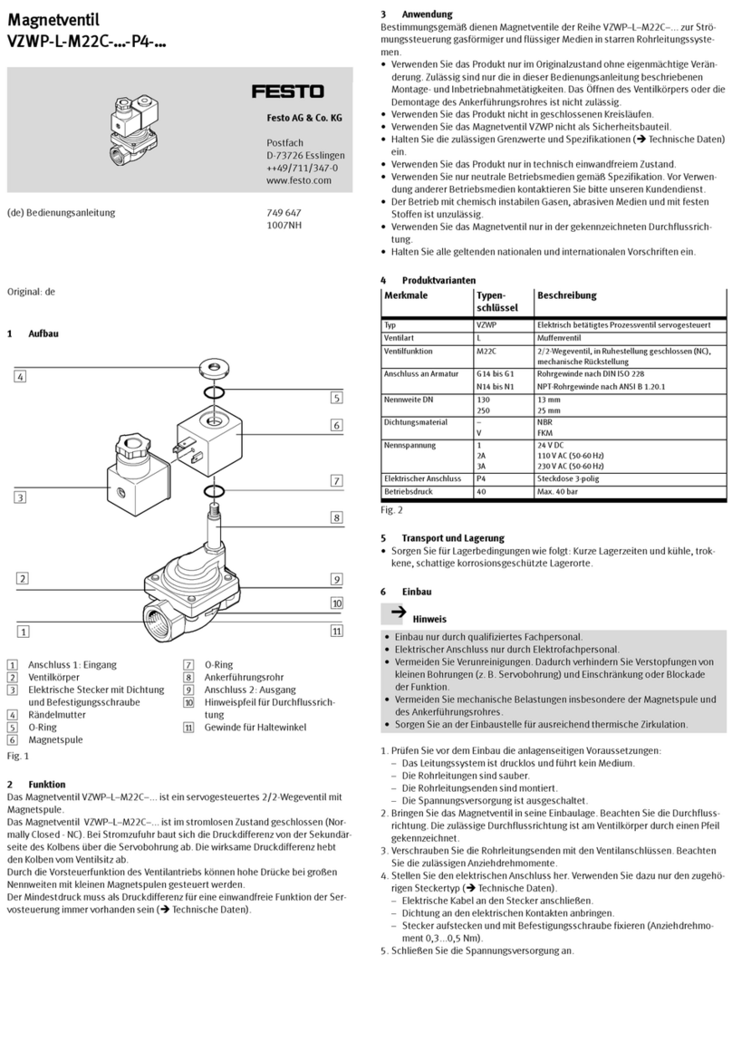
Festo VZWP-L-M22C-P4 Series User manual

Festo

Festo VZWP-L-M22C-P4 Series User manual

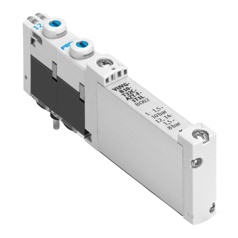
Festo VUVG 1T1L Series User manual

Festo

Festo VUVG 1T1L Series User manual

Festo HEL Series Instruction Manual

Festo

Festo HEL Series Instruction Manual

Festo DW Series User manual

Festo

Festo DW Series User manual

Festo CPX-E-4IOL User manual

Festo

Festo CPX-E-4IOL User manual

Popular Control Unit manuals by other brands

4D systems gen4-uLCD-32D quick start guide

4D systems

4D systems gen4-uLCD-32D quick start guide

AEG ELFAMATIC uC 3000 Operating and installation instructions

AEG

AEG ELFAMATIC uC 3000 Operating and installation instructions

Solaria PowerXT-R-AC quick start guide

Solaria

Solaria PowerXT-R-AC quick start guide

Honeywell Velociti Series Installation and maintenance instructions

Honeywell

Honeywell Velociti Series Installation and maintenance instructions

Rain Bird IQ-NCC Installation and user manual

Rain Bird

Rain Bird IQ-NCC Installation and user manual

AAON RSMZ Technical guide

AAON

AAON RSMZ Technical guide

Honeywell V5421C installation instructions

Honeywell

Honeywell V5421C installation instructions

Bosch Rexroth PSI 6500 Series technical information

Bosch

Bosch Rexroth PSI 6500 Series technical information

Digi XBee ZigBee S2C Getting started guide

Digi

Digi XBee ZigBee S2C Getting started guide

Argo-Hytos RPEX3-06 operating instructions

Argo-Hytos

Argo-Hytos RPEX3-06 operating instructions

Burkert 6013 operating instructions

Burkert

Burkert 6013 operating instructions

Veichi 300 Series Operation manual

Veichi

Veichi 300 Series Operation manual

National Instruments NI 9242 User manual and specifications

National Instruments

National Instruments NI 9242 User manual and specifications

MicroElektronika GSM click manual

MicroElektronika

MicroElektronika GSM click manual

Hyperdyne Labs Vortex 3 instructions

Hyperdyne Labs

Hyperdyne Labs Vortex 3 instructions

Kemper 145 2G Installation and operating instructions

Kemper

Kemper 145 2G Installation and operating instructions

ASAHI AV Series Installation, operation and maintenance manual

ASAHI

ASAHI AV Series Installation, operation and maintenance manual

Kessel Staufix SWA Installation and operating manual

Kessel

Kessel Staufix SWA Installation and operating manual

manuals.online logo
manuals.online logoBrands
  • About & Mission
  • Contact us
  • Privacy Policy
  • Terms and Conditions

Copyright 2025 Manuals.Online. All Rights Reserved.