manuals.online logo
Brands
  1. Home
  2. •
  3. Brands
  4. •
  5. Festo
  6. •
  7. Control Unit
  8. •
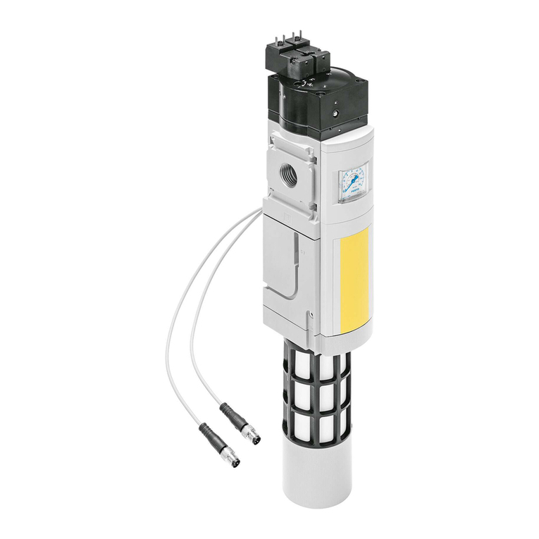
  9. Festo VPPM-6L-L-1-G18-0L6H-LK-S1 User manual

Festo VPPM-6L-L-1-G18-0L6H-LK-S1 User manual

Proportional pressure regulator valve
VPPM-…-LK-…
Festo AG & Co. KG
Ruiter Straße 82
73734 Esslingen
Germany
+49 711 347-0
www.festo.com
Operating instructions
(Translation of the original instructions)
8086184
2018-03b
[8086186]
For all available product documentation èwww.festo.com/pk
Proportional pressure regulator valve English.............................
IO-Link®is a registered trademark of the trademark holder in certain countries.
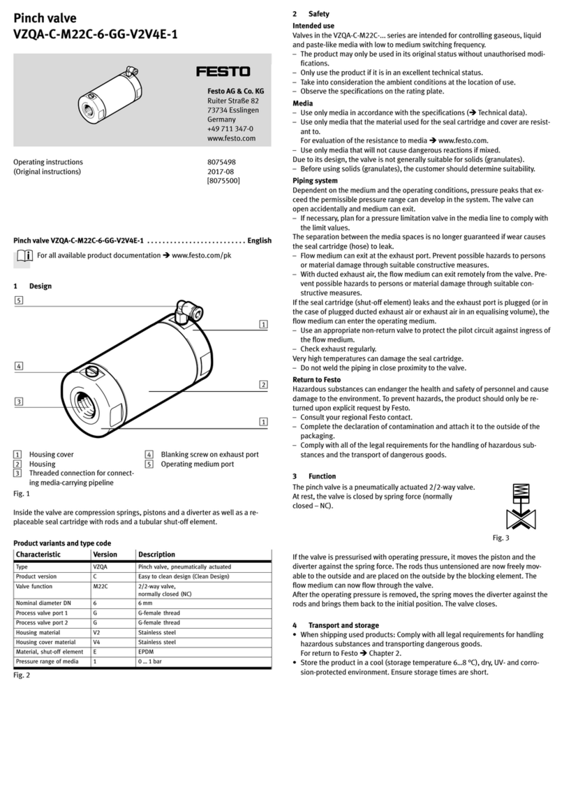
1 Application and function
The VPPM is intended for controlling a pressure
proportional to a specified setpoint value (input
word). A built-in pressure sensor records the
pressure at the working port and compares this
value with the setpoint value. If there are devi
ations between the actual value and the set
point value, the control valve is actuated until
the outlet pressure reaches the setpoint value. Fig. 1
2 Characteristics in the type code
Type code
1
23
56
4
7
VPPM - 6L - - - - - -L 1 G18 0L6H LK S1
Item Characteristics Significance
1Nominal width in [mm] 6, 8, 12
Valve type F (flange), L (sleeve)
2Dynamic response class L (Low)
3Valve function 1 (3-way pressure regulator, normally
closed)
4Pneumatic connection
– Flange/sub-base F6 (NW 6 mm), F8 (NW 8 mm)
– ISO thread G18 (x"), G14 (¼"), G12 (½")
5Control ranges
– Lower pressure value 0L (0 bar)
– Upper pressure value 2H (2 bar), 6H (6 bar), 10H (10 bar)
6– Setpoint specification IO-Link-specific
7Accuracy S1 (1 %)
Fig. 2
3 Requirements for product use
 Installation and commissioning is to be carried out only by qualified personnel,
in accordance with the documentation.
 Take into consideration the ambient conditions at the location of use.
 All applicable national and international regulations must be complied with.
 Use the product in its original status, without any unauthorised product
modifications.
 Ensure that the compressed air is properly prepared (èTechnical data).
 Pressurize your entire system slowly. There will then be no uncontrolled
movements.
Range of application and certifications
In combination with the UL mark on the product, the information included in this
section is also applicable for compliance with the certification requirements of
Underwriters Laboratories Inc. (UL) for USA and Canada.
UL approval information
Product category code QUYX, QUYX7
File number E322346
Standards taken into account UL 610101, CAN/CSAC22.2 No. 610101
UL identification
Fig. 3
The product must be powered by a power source that fulfills the requirements of
an energy-limited circuit in accordance with IEC/EN/UL/CSA 61010-1 or a power
source with limited power (LPS)in accordance with IEC/EN/UL/CSA 60950-1 or
IEC/EN/UL/CSA 62368-1 or a Class 2 circuit in accordance with NEC or CEC.
3.1 Connections and mounting holes (in-line valve)
12
3
54
3
1Electr. connecting plug (5-pin)
2Air (2), pressure output
3Through holes for mounting. For
size ½" in the manifold block
4Compressed air (1), supply port
5Exhaust (3)
Fig. 4
4 Installation
4.1 Mechanical
 Make sure there is sufficient space for the connecting cable and tubing connec
tions. In this way you will prevent the cable and tubes from being bent.
 Place the VPPM as close to the consumer as possible. This leads to improved
control precision and shorter response times.
Wall mounting
 Fasten the in-line valve of size x" and ¼"
at the intended position with two M4 screws.
If necessary, use bracket type VAME-P1-A
(èFig. 5) to do this. When using the bracket,
the VPPM may only be loaded statically.
 Fasten the in-line valve of size ½" at the
intended position with two M5 screws
(tightening torque 2.0 Nm).
 Mount the flange valve of size x" and ¼"
onto the manifold rail VEABM-P1-SF-G18…
(tightening torque approx. 1.5 Nm). Fasten
the manifold rail at the intended position
with two M6 screws.
Fig. 5
H-rail mounting
 Mount the H-rail adapter with the included screws (for size x": M4 x 65,
for size ¼": M4 x 77) to the in-line valve VPPM-6L/8L (tightening torque
approx. 1.5 Nm) èFig. 6.
1
2
3
ÓÓ
ÓÓ
ÓÓ
ÓÓ
ÓÓ
ÓÓ
Ô
Ô
4
5
1H-rail adapter VAME-P1-T
2In-line valve VPPM-6L/8L
3Mounting screws
4H-rail clamping unit
5H-rail
Fig. 6
 Hang the VPPM-6L/8L onto the H-rail.
 Secure the VPPM-6L/8L with the H-rail clamping (tightening torque 1.5 Nm).
4.2 Pneumatic (in-line valve)
 Attach the pneumatic tubing to the following connections: (èFig. 4):
– Supply port (1) item 4,pressure output (2) item 2
 Mount a silencer at the exhaust (3) item 5or remove the exhaust air with
ducts.
Operating medium
Note
Too much residual oil content in the compressed air will reduce the service life of
the valve.
 When using bio-oils (oils that are based on synthetic esters or native esters,
e.g. rapeseed oil methyl ester), the maximum residual oil content of
0.1 mg/m³ must not be exceeded (èISO 8573-1:2010 [-:-:2]).
4.3 Electrical
Warning
Risk of injury due to electric shock.
 For the electric power supply, use only PELV circuits that ensure a reliable
electric disconnection from the mains network.
 IEC 60204-1/EN 60204-1 to be screwed in.
Note
 Long signal lines pick up more interference. Make certain that the signal lines
are always shorter than 20 m (see also IO-Link specification IEC 61131-9).
 The IO-Link Master may have either port type A or port type B.
 On the device is a 5-pin plug, M12, port type A.
 Use the pre-assembled cable with socket from Festo (accessories
èwww.festo.com/catalogue). You can then guarantee that the specified
degree of protection IP 65 and EMC are fulfilled.
 The tightening torque of the M12 plug socket with cable must not exceed
0.5 Nm.
 The individual pins on the electrical connection are assigned as follows:
M12 socket,
(5-pin, A-coded)
Pin Assignment Function
124 V DC(UEL/SEN) Operating voltage supply (PS)
2n. c. Not connected
30 V DC (UEL/SEN)Operating voltage supply (PS)
4C/Q Data communication
5n. c. Not connected
Lug (on
the plug)
FE Functional earth
Fig. 7
5 Commissioning
Note
The VPPM interprets setpoint value specifications that are smaller than 1 % full
scale as 0.
 Connect the VPPM to an IO-Link master or an I-Port master.
– The VPPM communicates with the respective master via the corresponding
protocol. The setpoint and actual values are transferred cyclically, the dia
gnostic values acyclically.
– The valve has a 16-bit input word (setpoint value) and a 16-bit output word
(actual value).
– If the desired data rate is not set automatically with IO-Link, the data rate can
be forced through a write command to ISDU parameter 0x0048: COM3 = 03,
COM2 = 02. For I-Port, the data rate is always set to COM3.
– Power supply with 24 V DC is provided through the IO-Link master.
 Pressurize the VPPM with an input pressure at least 1 bar higher than the max
imum desired output pressure. An outlet pressure p2 proportionate to it is then
set. The following outlet pressure is then assigned to the setpoint value signal:
Type code Outlet pressure
with signal 1 % Full scale
Outlet pressure
with signal 100 % Full scale
VPPM-…-0L2H-… 0.02 bar 2 bar
VPPM-…-0L6H-… 0.06 bar 6 bar
VPPM-…-0L10H-… 0.1 bar 10 bar
Fig. 8
 Select a suitable parameter set (èChapter 6).
6 Parameterisation
Parameter
number
ISDU
index
Sub-
index
Parameter of the proportional pressure regulator
00x043 1Monitoring parameterisation errors
Activate limit monitoring for the output word
Monitoring of load voltage Uout/Uval
10x043 2ID (type selection) (read only)
20x043 3Unit for pressure specifications (limit value and current
pressure value)
30x043 4Control behaviour (presets)
Input signal
Measured value smoothing
8 ... 11 0x068 0Condition counter limit (switching cycle counter)
12 0x069 0Low byte lower limit value
13 High byte lower limit value
14 0x06A 0Low byte upper limit value
15 High byte upper limit value
16 ... 19 0x06B 0Condition counter actual value (updates all 256 steps) is
reset by writing a “0” to 0x68
Fig. 9
Valve parameter: Monitoring
Parameter no. 0
Description With the proportional pressure regulator, monitoring of individual errors can be
independently activated or deactivated (suppressed):
– Monitoring of parameterisation error: Monitors valve parameterisation. An er
ror message is generated for the following implausible settings:
Upper limit value ≤ lower limit value
Upper limit value < 0 or > control range (èFig. 17)
Lower limit value < 0
– Limit monitoring: Defines whether the limit values are monitored, and
a diagnostic message is generated when the limit values are exceeded or
fallen below.
– Monitoring of load voltage: Defines whether the load voltage Uout/UVal is
monitored. If the voltage drops too much (for values èTechnical data in
Fig. 25), a diagnostic message is generated.
Active monitoring causes the error to be sent to the IO-Link or I-Port master and
displayed through the Error LED of the VPPM
Bit Bit 7: Monitoring of parameterisation errors
Bit 6: Limit monitoring
Bit 2: Monitoring of load voltage Uout/val
Values Bit 76543210 Setting:
0xxxxxxx Monitoring of parameterisation errors
inactive
1 x x x x x x x Monitoring of parameterisation errors
active
x0x x x x x x Limit monitoring inactive
x 1 x x x x x x Limit monitoring active
xxxxx0x x Monitoring of Uout/Uval inactive
x x x x x 1 x x Monitoring of Uout/Uval active
Comment Bold = presetting, x = value is unimportant for this setting
Fig. 10
Valve parameter: ID
Parameter no. 1
Description Provides valve identification for I-Port
Values In-line valve Flanged valve
0x01: 1/8" 10 bar 0x31: F6 10 bar
0x02: 1/8" 6 bar 0x32: F6 6 bar
0x03: 1/8" 2 bar 0x33: F6 2 bar
0x11: 1/4" 10 bar 0x41: F8 10 bar
0x12: 1/4" 6 bar 0x42: F8 6 bar
0x13: 1/4" 2 bar 0x43: F8 2 bar
0x21: 1/2" 10 bar
0x22: 1/2" 6 bar
0x23: 1/2" 2 bar
Comment Read only
Fig. 11
Note
When changing the unit for pressure specifications, the parameters for the limit
values and the input word (setpoint value) are not automatically converted.
 When changing the unit, also change the parameters for the upper/lower limit
value and the input word (èFig. 17).
Valve parameter: Unit for pressure indications
Parameter no. 2
Description Defines the unit for pressure indications (limit values, pressure setpoint
specification and pressure actual value specification).
Bit Bit 1.0
Values Bit 1 0 Setting Resolution
0 0 mbar (preset) 1 mbar/bit
01kPa 1 kPa/bit
10psi 0.1 psi/bit
1 1 reserved
Comment To avoid accidental pressure fluctuations, set the input word before conversion
of the unit to zero.
Fig. 12
Valve parameters: Setting of the control behaviour (presets), output data type
and measured value smoothing
Parameter no. 3
Description Parameterised via this function number are:
– Control behaviour (presets): Defines the characteristic curve used for
controlling a setpoint pressure.
– Output data type: Offers 3 options for what is presented in the output word
(data format èFig. 16):
– Output of the current pressure value
– Output as comparator bit:
Bit 0 = 0: Pressure value is outside the control range
Bit 0 = 1: Pressure value is in the control range
– Combined output of current pressure value and comparator bit. Bit 0 is used
as the comparator bit, as above It is no longer used for representing
the pressure value.
– Measured value smoothing: Sets how strongly the measured values are
smoothed for limit monitoring. This can suppress possible malfunctions.
Bit Bit 1, 0: Control behaviour (presets)
Bit 3, 2: Output data type
Bit 5, 4: Measured value smoothing
Values Bit 543210
Control behaviour setting (presets):
x x x x 0 0 Reserved
x x x x 0 1 Fast
xxxx10 General (presetting)
xxxx11 Precise
Setting of output data type:
x x 0 0 x x Reserved
xx01x x Current pressure value in the output word
(presetting)
x x 1 0 x x Comparator bit (bit 0 in the output word)
x x 1 1 x x Current pressure value and comparator bit
Settings of measured value smoothing:
00x x x x No measured value smoothing (presetting)
0 1 x x x x Smoothing over 2 values
1 0 x x x x Smoothing over 4 values
1 1 x x x x Smoothing over 8 values
Comment Bold = presetting, x = value is unimportant for this setting
Fig. 13
Valve parameter: Condition counter solenoid coil
Parameter no. 8...11 Condition counter limit
Manual A limit value for a counter (condition counter) can be set for the internal
solenoid coil in the pilot control of the pressure regulator. A message is
displayed if the limit value is exceeded, which is sent to the IO-Link master.
Bytes 11 or 8: High byte or low byte of the limit value (32 bit values, hexadecimal)
Values FFFFFFFFh:Condition counter activated, but limit value inactive
(preset)
2DC6C0h:(Example) Condition counter activated and limit value
3,000,000dset.
0: Condition counter inactive (counter and diagnostic message
deactivated, counter reset, counter actual value can be read
through 0x6B.)
Fig. 14
Valve parameter: lower / upper limit
Parameter no. 12…13 Lower limit value
14…15 Upper limit value
Description The lower and upper limit values for the pressure and diagnostic messages are
set with these parameters. Undershooting or overshooting of limit values is only
signaled if the output word diagnostics is activated via the limit value
monitoring parameter (èFig. 10).
Byte 12 or 14 low byte
13 or 15 high byte
Values Presets
– Lower limit value = 0 (low byte = 0; high byte: 0)
– Upper limit value: Max. pressure value of the valve type (èFig. 17)
Remarks The upper limit value must always be greater than the lower limit value.
The limit values are checked for validity during parameterisation. If invalid
parameters are present and the module parameter “Monitoring of
parametrisation errors” is active, a corresponding error is signaled
(èChapter 12).
Fig. 15
Process Data
Input word (setpoint value, 16 bit)
Output word (pressure value, 16 bit)
LSB (bit 0) can be used as a comparator bit with parameterisation of output data.
Fig. 16
Proportional
pressure regulator
Control
range
Range of values 1)
input word (decimal)
Range of values 1)
input word (hex)
VPPM-...-0L2H-LK-S1 0 … 2 bar 0 … 2000/290/200 0h… 07D0h/0122h/00c8h
VPPM-…-0L6H-LK-S1 0 … 6 bar 0 … 6000/870/600 0h… 1770h/0366h//0258h
VPPM-...-0L10H-LK-S1 0 … 10 bar 0 … 10000/1450/1000 0h… 2710h/05AAh/03E8h
1) If mbar/psi/kPa is set as the pressure unit
Fig. 17
Recommended parameter sets VPPM size x" (presets èFig. 13)
Tube
length 1)
Open
system
Output volumes in ml
0 … 100 100 … 1000 > 1000
0 m 3 3 2 1
1 m 3 3 2 2
3 m 3 3 3 2
5 m 3 3 3 2
1) With tubing diameter 6 mm or 8 mm
Fig. 18
Recommended parameter sets VPPM ¼" and ½" (presets èFig. 13)
Tube
length 1) 2)
Open
system
Output volumes in ml
Size ¼"
0 … 500 500 … 2000 > 2000
Size ½"
0 … 2000 2000 … 10000 > 10000
0 m 3 1 2 3
1 m 3 1 2 3
3 m 3 2 3 3
5 m 3 3 3 3
1) With tubing diameter 8 mm or 10 mm (1/4")
2) With tubing diameter 12 mm or 16 mm (1/2")
Fig. 19
7 Operation
Note
When switching off the VPPM, first make sure that the setpoint value is set to 0,
then that the supply pressure and finally the supply voltage are switched off.
Display and operating components
2
11LED (green) POWER
2LED (red) ERROR
Fig. 20
8 Maintenance and care
For cleaning:
 Switch off the following energy sources before cleaning the exterior of the
device:
– operating voltage
– compressed air
 If the VPPM is dirty, clean the exterior with a soft cloth.
The permitted cleaning agents are mild soapy water (max. +50 °C) or all non-abras
ive media.
9 Disassembly
For disassembly:
 Switch off the following energy sources:
– operating voltage
– compressed air
 Disconnect the relevant connections from the VPPM
 Remove the VPPM from the mounting surface/H-rail.
10 Accessories
èwww.festo.com/catalogue
11 Safety setting
Wire break IO-Link
Data communication The last value is saved. In the medium term, the pressure at the
output can increase or diminish.
Supply voltage The last value is saved. The outlet pressure is maintained unregu
lated. In the medium term, the pressure at the output can increase
or diminish.
Fig. 21
12 Error messages
Cause Status of the LED indicators
LED (green) POWER LED (red) ERROR
Communication inactive Lights up Off
Communication active Flashes 1 Hz (9:1) Off
Error / diagnostics Off èFig. 23
Internal error Off Flashes (5 Hz)
Fig. 22
Error number Manual Status of the red LED indicators
ERROR
0x5100 Undervoltage < 18 V Lights up
0x8CA1 Lower limit undershot Off
0x8CA2 Upper limit exceeded Off
0x8C42 Condition counter limit value ex
ceeded
Off
0x6320 Error in parameterisation upper/
lower value
Lights up only if parameterised:
– Lower limit < 0
or
– Upper limit < lower limit
Fig. 23
Malfunction Possible cause Remedy
VPPM does
not react
Supply voltage not applied, POWER
LED does not light up
Check connection of the 24 V DC
supply voltage.
Data communication lacking Check control unit and connection.
Flow rate too low Restriction of the flow cross section
due to connection technology (swivel
fittings), POWER LED lights up
Use alternative connections.
Malfunction Possible cause Remedy
Pressure rise
too slow
Large cylinder volume and long tube
length
Select another parameter set.
Pressure
constant
despite
modified
setpoint
specification
Break in supply cable
The last outlet pressure set remains
unregulated. In the medium term, the
pressure at the output can increase or
diminish.
Replace supply cable.
Inlet pressure too low p1 Increase inlet pressure.
Failure of data communication Replace data transmission line.
Fig. 24
13 Technical data
VPPM 2 bar
29 psi
6 bar
87 psi
10 bar
145 psi
Design Propor tional pressure regulator
Mounting position Any, preferably flat (display components facing upwards)
Operating medium Compressed air in accordance with ISO 8573-1:2010 [7.4.4],
with use of ester oil, compressed air in accordance with
ISO 8573-1:2010 [-:-:2]
Inert gases
Pressure ranges
– Supply pressure p1 [bar] Max. 4 Max. 8 Max. 11
– Control range
(output pressure)
p2
[bar] 0.02 … 2 0.06 … 6 0.1 … 10
The inlet pressure p1 must be at least 1 bar higher than
the outlet pressure p2.
Total leakage when new [l/h] < 5
Ports Gx", G¼" , G½"
Nominal size
– Pressurisation [mm] Size x": 6
Size ¼": 8
Size ½": 12
– Venting [mm] 4.5 (at x"), 6 (at ¼"), 12 (at ½")
Degree of protection IP 65 when mounted, with tightened mounting screws,
in combination with plug socket according to accessories.
Permissible temperature range
– Environment [° C] 0 … +60
–Medium [° C] +10 … +50
– Storage [° C] –10 … +70
Electrical connection Pin contact M12x1, 5-pin
Permissible operating
voltage
[V DC] 18 … 30 (permissible residual ripple 1.3 Vpp (IEC61131-9)
Max. electrical power consumption
–Sizexand ¼[W] 7
–Size½[W] 12
Max. perm. supply and
signal line length
[m] 20
Overall accuracy
– Class S1
(1 %) +0.5 x hysteresis
[bar] 0.025 0.075 0.125
Hysteresis 0.5 % full scale
IO-Link type VPPM-...-LK-S1
– Cable characteristics
Observe IO-Link-specific data
IO-Link specification Associated IO-Link IODD (èwww.festo.com/sp)
– V1.0 V1.1
–V1.1 V1.1
Data rate Supports all IO-Link data transmission rates
Electromagnetic Compatibility 1)
– Emitted interference
– Interference immunity
See declaration of conformity èwww.festo.com
CE conformity for industrial installations fulfilled
Vibration and shock The following specifications do not apply for mounting
the VPPM in-line valve to the bracket VAME-P1-A.
– Vibration Tested in accordance with DIN/IEC 68/EN 60068 parts 2-6;
for wall mounting: Path 0.35 mm at 10 ... 60 Hz, 5 g
acceleration at 60 ... 150 Hz
– Shock Tested in accordance with DIN/IEC 68/EN 60068 parts 2-27;
for wall mounting: ±30 g at 11 ms duration; 5 shocks
per direction
Materials
– Housing Wrought aluminium alloy: PAXMD6 GF50/gr-P
– Seals Nitrile rubber
– Lubrication Silicone-free
Weight
–Sizex[g] 400
–Size¼[g] 560
–Size½[g] 2050
Data of the UL certification
– Altitude of use Up to 2000 m
1) The valve is intended for use in an industrial environment. Outside of industrial environments,
e.g. in commercial and mixed-residential areas, actions to suppress interference may have to be
taken.
Fig. 25

This manual suits for next models

1

Other Festo Control Unit manuals

Festo DSMI Series User manual

Festo

Festo DSMI Series User manual

Festo VAEM-V-S8EPRS2 User manual

Festo

Festo VAEM-V-S8EPRS2 User manual

Festo DRRD-PS1 Series User manual

Festo

Festo DRRD-PS1 Series User manual

Festo MPYE-5-***-B series User manual

Festo

Festo MPYE-5-***-B series User manual

Festo CPX-E-PN User manual

Festo

Festo CPX-E-PN User manual

Festo VIA 03-FB Series Parts list manual

Festo

Festo VIA 03-FB Series Parts list manual

Festo HEL Series Instruction Manual

Festo

Festo HEL Series Instruction Manual

Festo CPX-FB6 User manual

Festo

Festo CPX-FB6 User manual

Festo MSE6-D2M Parts list manual

Festo

Festo MSE6-D2M Parts list manual

Festo CPI-CL Series User manual

Festo

Festo CPI-CL Series User manual

Festo CPX-P-8DE-N Series Operating and installation instructions

Festo

Festo CPX-P-8DE-N Series Operating and installation instructions

Festo VIFB13 Series User manual

Festo

Festo VIFB13 Series User manual

Festo VPCB T22Series User manual

Festo

Festo VPCB T22Series User manual

Festo MX-2-1/4 User manual

Festo

Festo MX-2-1/4 User manual

Festo CPX-E-4IOL User manual

Festo

Festo CPX-E-4IOL User manual

Festo DSMI-***-B Series User manual

Festo

Festo DSMI-***-B Series User manual

Festo VMPA1-HS User manual

Festo

Festo VMPA1-HS User manual

Festo DADM-EP-G6 User manual

Festo

Festo DADM-EP-G6 User manual

Festo HSP AE Series User manual

Festo

Festo HSP AE Series User manual

Festo VZXA-K Operation and maintenance manual

Festo

Festo VZXA-K Operation and maintenance manual

Festo CTEU-DN Parts list manual

Festo

Festo CTEU-DN Parts list manual

Festo CPE PRS Series User manual

Festo

Festo CPE PRS Series User manual

Festo VZXA Series Setup guide

Festo

Festo VZXA Series Setup guide

Festo CPX-4AE-4AA-H Operating and installation instructions

Festo

Festo CPX-4AE-4AA-H Operating and installation instructions

Popular Control Unit manuals by other brands

Spirax Sarco SV615 Installation and maintenance instructions

Spirax Sarco

Spirax Sarco SV615 Installation and maintenance instructions

SYR STS 5 user manual

SYR

SYR STS 5 user manual

Elatec TWN4 MULTITECH LEGIC M user manual

Elatec

Elatec TWN4 MULTITECH LEGIC M user manual

Viessmann Vitotrol 350-C operating instructions

Viessmann

Viessmann Vitotrol 350-C operating instructions

eta G10.21A Technical Communication

eta

eta G10.21A Technical Communication

Graco CSP Series instructions

Graco

Graco CSP Series instructions

AWID SENTINEL-SENSE MPR-1510 Installation & operation manual

AWID

AWID SENTINEL-SENSE MPR-1510 Installation & operation manual

Waeco Switch200VTO Installation and operating manual

Waeco

Waeco Switch200VTO Installation and operating manual

Nortel 1100 Series user guide

Nortel

Nortel 1100 Series user guide

CLA-VAL CRL-60 Installation operation & maintenance

CLA-VAL

CLA-VAL CRL-60 Installation operation & maintenance

LOVATO ELECTRIC EXP10 02 instruction manual

LOVATO ELECTRIC

LOVATO ELECTRIC EXP10 02 instruction manual

Pilz PIT es Set10u-5ns (AIDA) basic operating manual

Pilz

Pilz PIT es Set10u-5ns (AIDA) basic operating manual

Vega VEGAKON 61 operating instructions

Vega

Vega VEGAKON 61 operating instructions

Cino FuzzyScan COMBO RM3230 user guide

Cino

Cino FuzzyScan COMBO RM3230 user guide

Moog D661K Series operating instructions

Moog

Moog D661K Series operating instructions

Leuze electronic AC-CPB quick start guide

Leuze electronic

Leuze electronic AC-CPB quick start guide

EHUOYAN YHY521X user manual

EHUOYAN

EHUOYAN YHY521X user manual

Lenovo ThinkServer TS430 user guide

Lenovo

Lenovo ThinkServer TS430 user guide

manuals.online logo
manuals.online logoBrands
  • About & Mission
  • Contact us
  • Privacy Policy
  • Terms and Conditions

Copyright 2025 Manuals.Online. All Rights Reserved.