manuals.online logo
Brands
  1. Home
  2. •
  3. Brands
  4. •
  5. Festo
  6. •
  7. Controllers
  8. •
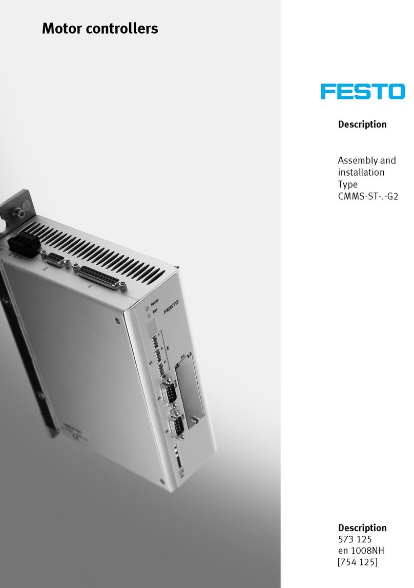
  9. Festo CMMS-AS G2 Series User manual

Festo CMMS-AS G2 Series User manual

CMMS-AS-...-G2
Festo AG & Co. KG
Postfach
73726 Esslingen
Germany
+49 711 347-0
www.festo.com
Brief description 8026148
1310NH
[8031346]
Original: de
Motor controller CMMS-AS-...-G2 English................................
Translation of the original instructions
You can find the complete documentation for the motor controller
CMMS-AS-...-G2 in PDF format on the CD-ROM accompanying the motor
controller or via the support portal www.festo.com/sp.
User documentation on the motor controller CMMS-AS-...-G2
Hardware description,
GDCP-CMMS-AS-G2-HW-...
Assembly, installation, pin allocations and error messages
Description of the safety function
STO, GDCP-CMMS-AS-G2-S1-...
Functional safety engineering for the motor controller with
the STO safety function
Description of function,
GDCP-CMMS-AS-G2-FW-...
Functional description and commissioning with FCT
Control interfaces and device profiles
Description of device profile FHPP,
P.BE-CMM-FHPP-SW-...
Control and parameterisation of the motor controller via
the device profile FHPP from Festo.
Description of device profile CiA 402,
P.BE-CMMS-FHPP-CO-SW-...
Description of the CAN interface of the motor controller.
Control and parameterisation via device profile CiA 402.
PROFIBUS description,
P.BE-CMM-FHPP-PB-SW-...
Description of PROFIBUS interface of the motor controller
DeviceNet description,
P.BE-CMMS-FHPP-DN-SW-...
Description of DeviceNet interface of the motor controller
Help on the FCT plug-in CMMS-AS User interface and functions of the CMMS-AS plug-in for
the Festo Configuration Tool www.festo.com
1 Safety and requirements for product use
1.1 Safety
Warning
Danger of electric shock
Touching live parts causes severe injuries and can lead to death:
– when the module or cover plate is not mounted on the card slot [EXT]
– when cables are not mounted to the plugs [X6] and [X9]
– when connecting cables are disconnected when powered.
The product must be installed in a control cabinet and may only be used if all
safeguarding has been initiated.
Before touching live parts during maintenance, repair and cleaning work and
when there have been long service interruptions:
1. Switch off power to the electrical equipment via the mains switch and secure
it against being switched on again.
2. After switch-off, wait at least 5 minutes discharge time and check that power
is turned off before accessing the controller.
Caution
Danger of burns from hot surfaces
Dependent on the load, housing temperatures > 80° C are possible in operation.
• Protect hot surfaces from contact in operation.
• Touch them only in a switched-off, cooled-off status.
Note
Danger from unexpected movement of the motor or axis
• Make sure that the movement does not endanger anyone.
• Perform a risk assessment in accordance with the EC Machinery Directive.
• Based on this risk assessment, design the safety system for the entire ma-
chine, taking into account all integrated components.
Intended use
The motor controller CMMS-AS-...-G2. is a digital positioning controller for servo
motors for
– supply and activation of the motor
– regulation of speed (current), torque and position.
The motor controller supports the following safety function:
– “Safe Torque Off ” (STO)
Category 3 / PL d in accordance with EN ISO 13849-1.
Use exclusively:
– in an excellent technical status
– in original status, without unauthorised modifications
– within the limits of the product defined through the technical data
–for the safety function within the specified service life of the switching elements
Section 9
– in an industrial environment
– as an installed device in a control cabinet.
Foreseeablemisuseofthesafetyfunction
– use outside or in a non-industrial area (residential area),
– use in applications where switching off can result in hazardous movements or
conditions.
Note
– The STO function is insufficient as the sole safety function for drives subject to
permanent torque or force (e.g. suspended loads).
– Bypassing of safety equipment is impermissible.
– Repairs to the motor controller are impermissible!
The STO (Safe Torque Off) function does not provide protection against
electric shock, only against hazardous movements!
In applications with extremely high requirement rates, the service life of the
switching elements must be taken into account in the design (replacement interval
for the motor controller) Section 9.
Attainable safety level in accordance with EN ISO 13849-1
The motor controller can be used in applications up to Cat. 3 / PL d in accordance
with EN ISO 13849-1. The achievable safety level depends on the other compon-
ents used to achieve a safety function.
1.2 Requirements for product use
For correct and safe use of the product:
• Comply with the connection and ambient conditions of the product and all con-
nected components specified in the technical data. Compliance with the limit
values and load limits permits operation of the product in compliance with the
relevant safety regulations.
• Observe the instructions and warnings in the documentation.
•For the safety function: For emergency stop applications, protection against
automatic restart must be achieved corresponding to the required safety cat-
egory, e.g. through an external safety switching device.
Qualification of the specialized personnel (requirements for the personnel)
The product may only be placed in operation by a qualified electrotechnician who
is familiar with:
– the installation and operation of electrical control systems,
– the applicable regulations for operating safety-engineering systems,
– the applicable regulations for accident protection and occupational safety, and
– the documentation for the product.
Diagnostic coverage (DC) for the safety function
Diagnostic coverage depends on the interconnection of the motor controller with
the control loop system as well as the implemented diagnostics measures.
If a potentially dangerous malfunction is recognised during the diagnostics, appro-
priate measures must be taken to maintain the safety level.
Note
Check whether a fault exclusion of cross circuits in the input circuit and connec-
tion wiring is possible in your application.
If necessary, use a safety switching device with short-circuit detection.
Range of application and certifications
The motor controller with integrated STO safety function is a safety-related part of
the control systems. The motor controller carries the CE mark.
Certificates and the declaration of conformity for this product can be
found www.festo.com.
2 Product overview
2.1 Device view
123
4
5
6
7
8
9
aJ
aA
aB
aC
aD
aE
aF
aG
aH
aE
1Front view
2Bottom view
3Top view
4Earthing screw (central PE
connection)
5LED status display
67-segments display
7[S1]: DIP switch
8[X5]: RS232/RS485
9[EXT]: Slot for CAMC-...
aJ [X4]: CAN bus
aA [M1]: SD memory card
aB [X3] STO interface
aC [X2] Encoder
aD [X6] Motor
aE Shield connection terminal
aF [X9] Power supply
aG [X10] Master/Slave
aH [X1] I/O interface
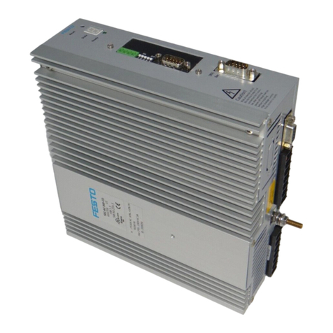
Fig. 1 Motor controller CMMS-AS-...-G2
2.2 Display and control elements
7-segments display
1)
Rotating outside
segments
Speed mode (speed adjustment):
Display changes corresponding to rotor position and speed.
Middle segment Controller enable active (motor is energised).
I Force mode (current control).
Pxxx Positioning mode, record number x x x
PHx Homing phase x
HTwo-channel safety function requested (DIN4 [X1.21] and Rel [X3.2]).
Point Start program (Bootloader) active.
Flashing point – Firmware file (memory card) is being read.
– Display of errors through the start program.
Exxy Error (E = error)
Number: Two-position main index (x x), single-position subindex (y)
Example: E 0 1 0 section 7.
–xxy– Warning
Number: Two-position main index (x x), single-position subindex (y).
Example:-170-section 7.
1) Several characters are displayed one after the other.
LED display
Ready Green Operating status/controller enable
Flashing green Parameter file (memory card) is being red/written
CAN Yellow Status display: CAN bus active
DIP switch
S1.1 … 7 CAN bus address or MAC-ID
S1.8 Automatic loading of new firmware and parameter files from memory card
S1.9 … 10 Setting the CAN-bus transmission rate
S1.11 Activation of the CAN-bus interface
S1.12 Terminating resistor for CAN-bus
3 Mechanical installation
3.1 Assembly
Observe the information on the installation dimensions and free spaces in
the hardware description GDCP-CMMS-AS-G2-HW-...
For vertical mounting onto a control cabinet mounting plate:
• Mount the accompanying mounting bracket to the motor controller.
• Use the motor controller exclusively in a control cabinet:
– The mounting position is vertical with the power supply lines [X9] leading
upwards.
– Mounting to the mounting brackets with M5 screws.
4 Electrical installation
Caution
Danger from unexpected movement
Faulty pre-assembled lines may destroy the electronics and trigger unexpected
movements of the motor.
• When wiring the system, use only the supplied plug connectors and preferably
the cables listed in the catalogue as accessories.
www.festo.com/catalogue
• Lay all flexible lines so that they are free of kinks and free of mechanical
stress; if necessary use chain link trunking.
Note
ESD (electrostatic discharge) can cause damage to the device or other system
parts at plug connectors that are not used.
• Before installation: Earth the system parts and use appropriate ESD equip-
ment (e.g. shoes, earthing straps etc.).
• After installation: Seal unassigned D-sub plug connectors with protective caps
(available at authorized dealers).
• Observe the handling specifications for electrostatically sensitive devices.
Warning
Danger of electric shock
Motor controllers are devices with increased leakage current (>10 mA). If wiring
is incorrect or the device is defective, high voltage can occur on the housing,
which can result in serious injury or even death if the housing is touched.
• Before commissioning, also for brief measuring and test purposes, connect
the PE protective conductor:
– to the earthing screw of the controller housing,
– to pin PE [X9.5], power supply. The cross section of the protective conduct-
or at PE [X9.5] must correspond at least to the cross section of the external
conductor L [X9.1].
• Observe the regulations of EN 50178 and IEC 60204-1.
Observe the information on safe and EMC-suitable installation and on
protective earthing in the Hardware description GDCP-CMMS-AS-G2-HW-...
4.1 I/O interface [X1]
Pin Value Assignment in 0 mode – positioning
1SGND 0V Screening for analogue signals
2DIN12/AIN0 –Mode bit 0/setpoint input 0
2)
3DIN 10 –Record selection bit 4 (high active)
4+VREF +10 V ±4 % Reference output for setpoint value potentiometer
5 – – –
6GND24 –Reference potential for digital I/O modules
7DIN 1 –Record selection bit 1 (high active)
8DIN 3 –Record selection bit 3 (high active)
9DIN 5 –Controller enable (high active)
10 DIN 7 –Limit switch 1
11 DIN 9 –Mode bit 1
12 DOUT1 24 V 100 mA Motion complete (high active)
1)
13 DOUT3 24 V 100 mA Common error (low active)
1)
14 AGND 0V Reference potential for analogue signals
15 DIN13/#AIN0 –/Ri = 20 kΩ Stop (low active)/reference potential AIN0
2)
16 DIN 11 –Record selection bit 5 (high active)
2)
17 AMON0 0…10V±4% Output: analogue monitor 0
18 +24VDC 24 V 100 mA Output: 24 V DC, looped through from [X9.6]
19 DIN 0 –Record selection bit 0 (high active)
20 DIN 2 –Record selection bit 2 (high active)
21 DIN 4 –Output stage enable (high active)
22 DIN 6 –Limit switch 0
23 DIN 8 –Start for the positioning procedure (high active)
24 DOUT0 24 V 100 mA Output: Controller ready for operation (high active)
25 DOUT2 24 V 100 mA Start acknowledged (low active)
1)
1) Default setting, configurable in the Festo Configuration Tool (FCT).
2) Pin allocation with control via analogue input
4.2 Encoder [X2]
[X2] Pin Value Description
1
2
3
4
5
6
7
8
9
10
11
12
13
14
15
1 M
T+
+3.3 V / 3 mA Temperature sensor, motor temperature.
2–U_SENS 0V Connected internally with pin 3
3GND 0V Reference potential US and M
T+
5#DATA U
SS
=5V RS485 data transmission line (differential)
6#SCLK U
SS
=5V Cycle output RS485 EnDat interface
9+U_SENS 5V(–0%…+5%) Connected internally with pin 10
10 US 5V(–0%…+5%) Operating voltage for EnDat encoder
12 DATA U
SS
=5V RS485 data transmission line (differential)
13 SCLK U
SS
=5V Cycle output RS485 EnDat interface
4.3 STO interface [X3]
Interface [X3] (Circuitry without use of the STO safety function)
[X3] Pin Value Description
1
2
3
4
5
6
124 V 24 V DC 24 V DC supply carried out
2REL 0V/24VDC Setting and resetting the relay for
interrupting the driver supply
30V 0V(GND24VDC) Reference potential for PLC (24 V DC)
4 – – –
5NC1 Max. 25 V AC,
30 V DC, 2 A
Potential-free feedback contact for driver
supply, NC contact
6NC2
Circuitry without use of the STO safety function
If you do not need the integrated safety function STO in your application,
to operate the motor controller you must bridge Pin 1 and Pin 2 at the X3
interface.
This deactivates the integrated safety function!
With this circuitry, safety in the application must be ensured through other
appropriate measures.
Use of the STO safety function
For intended use of the safety function STO – “Safe Torque Off ”, observe
the information in the STO description GDCP-CMMS-AS-G2-S1-...
Use the “Safe Torque Off” function (STO) whenever you have to reliably disconnect
the energy supply to the motor in your particular application. To ensure the func-
tion STO “Safe Torque Off”, the control ports DIN4 [X1.21] and Rel [X3.2] must be
connected in two channels through parallel wiring. This interface can be part of an
emergency stop circuit or a protective door arrangement, for example.
Recommendation for initial start-up without safety equipment:
Minimum circuitry with emergency stop switching device and two-channel switch-
off via the control ports REL [X3.2] and DIN4 [X1.21].
Note
Loss of the safety function.
Lack of the safety function can result in serious, irreversible injuries, e.g. due to
uncontrolled movements of the connected actuator technology.
– The STO function request must always run over X3.2 and X1.21 (end stage
enable).
– If uncontrolled coasting can result in a hazard or damage, additional meas-
ures are required.
– A clamping unit is actuated by the non-safety-relevant firmware of the CMMS-
AS-...-G2 motor controller.
• Make sure that no jumpers or the like can be inserted parallel to the safety
wiring, e.g. through the use of the maximum wire cross section of 1.5 mm² or
suitable wire end sleeves with insulating collars.
• Use twin wire end sleeves for looping through lines between neighbouring
devices.
• Comply with the specified environmental and connection conditions, in partic-
ular the input voltage tolerances.
• Place the motor controller in operation only if all safeguarding, including the
safety function, has been installed and checked.
• The safety function must be checked and, prior to the intended use, a corres-
ponding validation must be carried out.
4.4 CAN [X4]
[X4] Pin Value Description
5
1
2
3
4
6
7
8
9
2CANL 5V,Ri=60Ω CAN low, signal line
3GND –CAN GND, not galvanically isolated
5Screening –Connection for the cable screening
6GND –CAN GND, not galvanically isolated
7CANH 5V,Ri=60Ω CAN high signal line
4.5 Serial interface RS232/RS485 [X5]
[X5] RS232 Pin
1)
Value Description
5
1
2
3
4
6
7
8
9
2RS232_RxD 10 V, Ri >2kΩ Receive signal
3RS232_TxD 10 V, Ra <2kΩ Transmission signal
4RS485_A Positive transmission and receive signal
5GND 0V Reference potential 0 V DC
9RS485_B Negative transmission and receive signal
1) Connect only the pins for RS232 or RS485, dependent on the interface used!
4.6 Motor [X6]
[X6] Pin
1)
Value Description
1
2
3
4
5
6
7
8
1BR– 0V For motors EMMS-AS-…- TSB/TMB:
holding brake (motor)
2BR+ 24 V
3 M
T–
0V Temperature sensor (N/C contact, N/O
contact, PTC or KTY)
4 M
T+
+3.3V,5mA
5PE –PE connection of the motor cable
6 W Hardware
description
Connection of the three motor phases
7 V
8 U
1) In the motor and connecting cable, reliable separation of the motor temperature sensore from the motor
circuit must be ensured.
If third-party cables are used: Place the complete screening of the motor-
side cable flat on the plug or motor housing. Length ≤40 mm.
• Place the complete screening of the motor cable at the screening con-
nection terminal of the related motor controller so that the leaked cur-
rent can flow back into the controller causing it
• Do not use the complete screening as strain relief.
Connection of a holding brake
Holding brakes are not appropriate for braking the motor. They only serve
functional holding of the motor shaft. Additional measures are required for
use in safety-oriented applications.
4.7 Power supply [X9]
Protection against electric shock through protective extra-low voltage (PELV):
Warning
Danger of electric shock
• Only use PELV circuits in accordance with IEC/EN 60204-1 (protective
extra-low voltage, PELV) for the electrical power supply.
Also observe the general requirements for PELV circuits as per
IEC/EN 60204-1.
• Only use voltage sources which guarantee reliable electrical isolation of the
operating voltage in accordance with IEC/EN 60204-1.
The use of PELV circuits ensures protection from electric shock (protection from
direct and indirect contact) in accordance with IEC/EN 60204-1 (Electrical equip-
ment of machines, General requirements). A 24 V power supply unit used in the
system must satisfy the requirements of EN 60204-1 for DC power supply (beha-
viour during power interruptions, etc.).
[X9] Pin Value Description
1
2
3
4
5
6
7
1L1 1-phase
95 ... 250 V AC
Mains voltage connection for intermediate
circuit voltage
2 N
3IC + 320 V DC
(max 400 V DC)
Connection for external braking resistor
Hardware description
Not short-circuit proof against L1, N, PE
4BR-CH 0 V/400 V, max. 4 A
5PE PE Mains-side PE connection
624 V +24 V/1.7 A Supply of the control section, DOUT..., etc.
70V GND Common reference potential L1/24 V
4.8 Master/slave interface [X10]
[X10] Pin Description
6
7
8
9
2
1
3
4
5
1A/CLK/CW Tracking signal A/pulse CLK/steps CW
2B/DIR/CCW Tracking signal B/direction DIR/steps CCW
3 N Incremental encoder zero pulse N
4GND
1)
Reference GND for incremental encoder
5VCC Auxiliary supply, maximum load 100 mA
6#A/#CLK/#CW Tracking signal A/pulse CLK/steps clockwise CW
7#B/#DIR/#CCW Tracking signal B/direction DIR/steps CCW
8#N Zero pulse N
9GND
1)
Screening for the connecting cable
1) Pin 4 and pin 9 are connected internally
5 Commissioning
Note
Danger from unexpected movement of the motor or axis
• Make sure that the movement does not endanger anyone.
• Parameterise the motor controller with the Festo Configuration Tool (FCT)
before enabling the controller via DIN5 [X1.9].
– Bypassing of safety equipment is impermissible
Recommendation for first commissioning without safety equipment
section 4.3
Note
Damage to the motor controller
The motor controller is damaged in case of
– excessive operating voltage
– polarity reversal of the operating voltage connections
– interchange of operating voltage and motor connections
– short circuits in the motor circuit between the motor phases and PE
• Comply with the specified values for the supply voltage.
• Before switching on, check the connections [X9] and [X6].
• Check that no PE short circuit is present in the motor connection circuit.
Before switching on the power supply:
Check installation of the motor controller:
• Check all connections.
• Connect all PE protective conductors, even for brief measuring and test pur-
poses.
• Mounted module or cover plate on the card slot [EXT]. Mounted line on [X9] and
[X6].
Check operating status
1. Make sure that the controller enable is switched off (controller enable: DIN 5
[X1.9] ).
2. Switch on the power supplies of all devices. The READY LED on the front of the
device should now light up.
If the READY LED is not lit, there is a malfunction. If an “E” appears in the 7-seg-
ments display followed by a sequence of numbers, this is an error message and
you must eliminate the cause of the error.
Additional steps for preparation of commissioning can be found in the
Function description GDCP-CMMS-AS-G2-FW- ...
6 Obligations of the operator for the safety function
The operational capability of the safety device is to be checked at adequate inter-
vals. It is the responsibility of the operator to choose the type of check and time
intervals in the specified time period. The check is to be conducted so the flawless
functioning of the safety device in interaction with all the components can be veri-
fied.
Recommendation: Carry out a performance test at least every 24 hours.
7 Diagnostics and fault clearance
No. Message group Cause/measure
01-x Internal error – stack overflow Load approved firmware.
02-x Undervoltage in intermediate
circuit
Check power supply, intermediate circuit voltage,
undervoltage monitoring (threshold value).
03-x Temperature monitoring, motor Check parameterisation (current regulator, limits).
04-x Temperature monitoring,
electronics
Check installation conditions and cylinder sizing.
05-x Internal voltage supply Check 24 V logic supply. If error is present without
connected peripheral equipment repair.
06-x Intermediate circuit
(over-current)
Check motor, cable and motor controller.
07-x Intermediate circuit
(overvoltage)
Check design and connection of the braking resistor.
08-x Angle encoder Check encoder and encoder signals.
11-x Homing Check homing, switch arrangement.
12-x CAN Re-start CAN controller. Check CAN configuration in the
controller. Check wiring.
14-x Motor identification Check intermediate circuit voltage, encoder cable.
Motor blocked, e.g. holding brake does not release?
16-x Initialization Load firmware again. Hardware defective?
17-x Following error monitoring Enlarge error window. Parameterise acceleration to be
less. Motor overloaded?
18-x Temperature monitoring Check installation conditions.
19-x I²t monitoring Motor/mechanics blocked or sluggish?
21-x Current measurement If the error occurs repeatedly hardware defective.
22-x PROFIBUS Check slave address, bus termination, cabling.
25-x Firmware Update the firmware.
26-x Data flash Load factory setting. Hardware defective?
29-x SD card Check SD card.
31-x I²t monitoring Check motor and mechanical system.
32-x Intermediate circuit Check mains voltage/power supply, braking resistor.
35-x Fast stop Check parameterisation.
40-x Software end position Check target data and positioning range.
41-x Travel program Check parameterisation.
No. Message group Cause/measure
42-x Positioning Parameterisation/sequence control, homing?
43-x Limit switch error Check parametrisation, wiring and limit switches.
45-x STO error Check activation; the error must not recur.
64-x DeviceNet error Check configuration and network.
65-x DeviceNet error Check configuration and network.
70-x Operating mode error Check factor group and impermissible change.
79-x RS232 error Check wiring and transferred data.
8 Repair and disposal
Repair or maintenance of the motor controller is not permissible. If re-
quired, replace the motor controller.
Observe the local regulations for environmentally friendly disposal of elec-
tronic components.
9Technicaldata
The complete technical data on CMMS-AS-...-G2 can be found in the
Hardware description GDCP-CMMS-AS-G2-HW-...
When using the safety function, observe the special technical data and
restrictions on environmental conditions in dependence on required out-
put nominal power in the description STO GDCP-CMMS-AS-G2-S1-...
General technical data
Approvals
CE marking (see declaration of
conformity)
in accordance with EU Machinery Directive 2006/42/EC
in accordance with EU Low Voltage Directive
in accordance with EU EMC Directive
The device is intended for use in an industrial environment. Measures may need to be
implemented in residential areas for interference suppression.
Operating and environmental conditions
Permissible setup altitude above sea level
with nominal power [m] 1000
with power reduction [m] 1000 … 2000
Air humidity [%] 0 … 90 (non-condensing)
Protection class IP20
Degree of contamination 2
Ambient temperature
with nominal power [°C] 0…+40
with power reduction [°C] +40 … +50
Storage temperature [°C] –25 … +70
Vibrationandshockresistance
Operation in accordance with EN 61800-5-1, section 5.2.6.4
Transport in accordance with EN 61800-2, section 4.3.3
Power supply/braking resistor [X9]
Load voltage
Input voltage [V AC] 95 … 250 (single-phase)
Input current [A] 4…5
Mains frequency [Hz] 50 … 60
Logic supply
Nominal voltage [V DC] 24 ± 20 %
Nominal current (outputs unloaded, without holding
brake)
[A] 0.35
Max. current (incl. holding brake) [A] 1.7
Connection for external braking resistor
Braking resistor [Ω]≥100
Pulse power (for 500 ms) [W] ≤1600
Nominal power [W] ≤100
Operating voltage [V] 400
Safety reference data and safety specifications
Safety function STO Safe restart interlock (STO, Safe Torque Off)
Category 3Grading in categories as per EN ISO 13849-1
Performance Level PL d Performance level as per EN ISO 13849-1
T[Years] 20 Proof test interval
duration of use as per EN ISO 13849-1
MTTFd [Years] 528 Mean time to dangerous failure.
Due to the service life of the internal switching relay, the safety data for the STO function apply
for an annual actuation rate of Die nop = 500,000 / a (CMMS-AS-…G2 from Rev. 02).
Type test The functional safety engineering of the product has been
certified by an independent testing authority in accordance with,
see certificate www.festo.com
Certificate issuing authority MFS 09030
Reliable component Yes, for the STO safety function

Other manuals for CMMS-AS G2 Series

1

Other Festo Controllers manuals

Festo CMMP-AS-C2-3A User manual

Festo

Festo CMMP-AS-C2-3A User manual

Festo MPPES Series User manual

Festo

Festo MPPES Series User manual

Festo CMMB-AS-0x User manual

Festo

Festo CMMB-AS-0x User manual

Festo VPPM Series User manual

Festo

Festo VPPM Series User manual

Festo SEC-AC-305 Operating and installation instructions

Festo

Festo SEC-AC-305 Operating and installation instructions

Festo MS2-LFR Parts list manual

Festo

Festo MS2-LFR Parts list manual

Festo s CMMD-AS-C8-3A Guide

Festo

Festo s CMMD-AS-C8-3A Guide

Festo DFPD-Series Setup guide

Festo

Festo DFPD-Series Setup guide

Festo SFC-LACI Reference guide

Festo

Festo SFC-LACI Reference guide

Festo CMMP Series User manual

Festo

Festo CMMP Series User manual

Festo 03-B User manual

Festo

Festo 03-B User manual

Festo CECX-X-C1 Series User manual

Festo

Festo CECX-X-C1 Series User manual

Festo CPX Series User manual

Festo

Festo CPX Series User manual

Festo CMMO-ST-C5-1-DIOP User manual

Festo

Festo CMMO-ST-C5-1-DIOP User manual

Festo FEC-FC640 User manual

Festo

Festo FEC-FC640 User manual

Festo LRP-1/8-6 User manual

Festo

Festo LRP-1/8-6 User manual

Festo SEC-ST-48-6-P01 User manual

Festo

Festo SEC-ST-48-6-P01 User manual

Festo CMMS-ST-C8-7-G2 Guide

Festo

Festo CMMS-ST-C8-7-G2 Guide

Festo VPPI S1BT Series User manual

Festo

Festo VPPI S1BT Series User manual

Festo VEAB User manual

Festo

Festo VEAB User manual

Festo CMMS-ST-C8-7-G2 User manual

Festo

Festo CMMS-ST-C8-7-G2 User manual

Festo CPX-AP-I-4IOL-M12 User manual

Festo

Festo CPX-AP-I-4IOL-M12 User manual

Festo CPX-E-CEC-C1-EP Parts list manual

Festo

Festo CPX-E-CEC-C1-EP Parts list manual

Festo CMMO-ST-C5-1-DIOP User manual

Festo

Festo CMMO-ST-C5-1-DIOP User manual

Popular Controllers manuals by other brands

Motortech MIC3+ installation instructions

Motortech

Motortech MIC3+ installation instructions

Pentair ACU-TROL AK600 Installation and user guide

Pentair

Pentair ACU-TROL AK600 Installation and user guide

ero electronic ELK Series user manual

ero electronic

ero electronic ELK Series user manual

Emerson Dixell XM668D Installing and operating instructions

Emerson

Emerson Dixell XM668D Installing and operating instructions

Tech Controllers EU-28 SIGMA user manual

Tech Controllers

Tech Controllers EU-28 SIGMA user manual

Zeagle Razor Service manual

Zeagle

Zeagle Razor Service manual

Koganei Flow FSU manual

Koganei

Koganei Flow FSU manual

Deep Sea Electronics Plc DSE8810 Operator's manual

Deep Sea Electronics Plc

Deep Sea Electronics Plc DSE8810 Operator's manual

Vacon 100 INDUSTRIAL installation manual

Vacon

Vacon 100 INDUSTRIAL installation manual

Sharper Image 206172 owner's guide

Sharper Image

Sharper Image 206172 owner's guide

Onyx 80A instructions

Onyx

Onyx 80A instructions

SNT ACLE 101 Installation, operation and maintenance

SNT

SNT ACLE 101 Installation, operation and maintenance

Nexigo GripCon user manual

Nexigo

Nexigo GripCon user manual

Blichmann BrewCommander Assembly operation maintenance

Blichmann

Blichmann BrewCommander Assembly operation maintenance

POLA HD38 Handbook

POLA

POLA HD38 Handbook

Sacher Lasertechnik Pilot PC user manual

Sacher Lasertechnik

Sacher Lasertechnik Pilot PC user manual

artisan PMAC2-Lite Hardware reference manual

artisan

artisan PMAC2-Lite Hardware reference manual

nekos KATO 253 instruction manual

nekos

nekos KATO 253 instruction manual

manuals.online logo
manuals.online logoBrands
  • About & Mission
  • Contact us
  • Privacy Policy
  • Terms and Conditions

Copyright 2025 Manuals.Online. All Rights Reserved.