manuals.online logo
Brands
  1. Home
  2. •
  3. Brands
  4. •
  5. Festo
  6. •
  7. Controllers
  8. •
  9. Festo LFR EX4 Series Parts list manual

Festo LFR EX4 Series Parts list manual

Translation of the original instructions
1 Identification EX
Identification mark
II 2G Ex h IIC T6 Gb X
II 2D Ex h IIIC T85°C Db X
Tab. 1
2 Further applicable documents
NOTICE!
Technical data for the product can have different values in other documents. For
operation in an explosive atmosphere, the technical data in this document always
have priority.
All available documents for the product èwww.festo.com/pk.
3 Safety
3.1 Safety instructions
– The device can be used under the stated operating conditions in zone 1,
explosive gas atmospheres, and in zone 21, explosive dust atmospheres.
– The product may only be used in its original status without unauthorised
modifications.
– Only use the product if it is in perfect technical condition.
– All work must be carried out outside of potentially explosive areas.
– Observe the specifications on the product labelling.
– Earth the device via the earthing screw.
– Only use media in accordance with the specifications è 11 Technical data.
3.2 Intended use
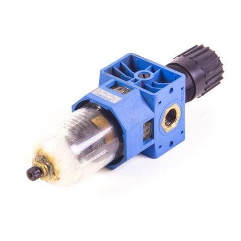
The filter regulating valve LFR regulates the compressed air in the subsequent
string to the set output pressure. The LFR thereby smoothes out pressure fluctu
ations.
3.3 Identification X: special conditions
– Danger of electrostatic discharge.
–Ambient temperature T18: -20 °C£Ta£+80°C
–Ambient temperature T3: -40 °C£Ta£+80°C
4 Further information
– Accessories èwww.festo.com/catalogue.
– Spare parts èwww.festo.com/spareparts.
5 Service
Contact your regional Festo contact person if you have technical questions
èwww.festo.com.
6 Product overview
6.1 Function
The filter regulating valve LFR removes dirt particles and condensate. The output
pressure can be adjusted within the pressure range.
6.2 Product variants
Ambient temperature T18: -20°C…+80°C
Connection Type Part number
LFR1/4D5MOMIDIT18EX4 4772764
LFR1/4DOMIDIT18EX4 4772765
LFR1/4D165MOMIDIT18EX4 4772766
LFR1/4D16OMIDIT18EX4 4772767
LFRN1/4D5MOMIDIT18EX4 4772772
LFRN1/4DOMIDIT18EX4 4772773
LFRN1/4D165MOMIDIT18EX4 4772774
¼"
LFRN1/4D16OMIDIT18EX4 4772775
LFR1/2D5MOMIDIT18EX4 4772768
LFR1/2DOMIDIT18EX4 4772769
LFR1/2D165MOMIDIT18EX4 4772770
LFR1/2D16OMIDIT18EX4 4772771
LFRN1/2D5MOMIDIT18EX4 4772776
LFRN1/2DOMIDIT18EX4 4772777
LFRN1/2D165MOMIDIT18EX4 4772778
½"
LFRN1/2D16OMIDIT18EX4 4772779
Tab. 2
Ambient temperature T3: -40°C…+80°C
Connection Type Part number
LFR1/4D5MOMIDIT3EX4 5271792
LFR1/4DOMIDIT3EX4 5271793
LFR1/4D165MOMIDIT3EX4 5271794
LFR1/4D16OMIDIT3EX4 5271795
LFRN1/4D5MOMIDIT3EX4 5271800
LFRN1/4DOMIDIT3EX4 5271801
LFRN1/4D165MOMIDIT3EX4 5271802
¼"
LFRN1/4D16OMIDIT3EX4 5271803
LFR1/2D5MOMIDIT3EX4 5271796
LFR1/2DOMIDIT3EX4 5271797
LFR1/2D165MOMIDIT3EX4 5271798
LFR1/2D16OMIDIT3EX4 5271799
LFRN1/2D5MOMIDIT3EX4 5271804
LFRN1/2DOMIDIT3EX4 5271805
LFRN1/2D165MOMIDIT3EX4 5271806
½"
LFRN1/2D16OMIDIT3EX4 5271807
Tab. 3
7 Assembly and installation
1Indication of flow direction 2Plug screw
Fig. 1
7.1 Filter regulator
1. Observe the flow direction 1 after 2.
2. Place the device at least 80mm below the filter bowl.
3. Position the device vertically (_5°).
When assembling filter combinations, observe the sequence along the flow direc
tion.
7.2 Pressure gauge
1. Remove the plug screw 2.
2. Turn pressure gauge with seal to the stop.
8107996
LFR-...-EX4-...
Filter regulator
8107996
201902b
[8107185]
Instructions| Operating
Festo SE & Co. KG
Ruiter Straße 82
73734 Esslingen
Germany
+49 711 3470
www.festo.com
7.3 Assembly with a service unit component of the same size
NOTICE!
If nonEx products are used, certification is revoked.
1Subbase
2Existing service unit component
(nonEx product)
3Spacer bolt
4Seal
5Filter bowl
6Earthing screw
7Threaded bolt FRBD (not in scope
of delivery)
Fig. 2
1. Remove subbase 1 from both devices on the sides to be fitted together.
2. Screw the threaded bolt 7 into the device.
3. Remove the subbase from the respective addon device and drive out the
corresponding spacer bolts 3 (drive out in the flow direction).
4. Mount the addon device with the subbase. Insert a seal 4 between the indi
vidual devices and the subbase.
7.4 Installation on pneumatic actuators
• Screw the connectors into the pneumatic connections using a suitable sealing
material.
8 Commissioning
WARNING!
The discharge of electrostatically charged parts can lead to ignitable sparks.
• Prevent electrostatic charging by taking appropriate installation and cleaning
measures.
• Include the device in the system equipotential bonding.
• Operation without the rotary knob is not permissible.
• Use the knurled nut only for installation with an earthed mounting bracket.
When using other mounting components, remove the knurled nut.
NOTICE!
The input pressure p1 is at least 1bar higher than the output pressure p2.
NOTICE!
Strong chargegenerating processes can charge nonconductive layers and coat
ings on metal surfaces.
NOTICE!
Escaping exhaust air can swirl up dust and create an explosive dust atmosphere.
NOTICE!
Particulate matter in the compressed air can cause electrostatic charges.
NOTICE!
Related type of ignition protection: c (constructional safety)
1. Unlock the rotary knob. To do this, pull the rotary knob away from the hous
ing.
2. Turn the rotary knob closed (direction "–").
3. Pressurise the system slowly.
4. Open the rotary knob (direction "+") until the desired pressure is displayed
on the pressure gauge.
5. Lock the rotary knob. To do this, press the rotary knob towards the housing.
9 Service
The condensate can be drained using the screw in regular intervals, depending on
the application.
Replacing the filter cartridge
1. Exhaust the device.
2. Unscrew the filter bowl.
3. Unscrew the filter plate.
4. Remove the used filter cartridge.
5. Place a new filter cartridge on the filter plate and secure it in place.
6. Tighten the filter bowl.
7. Recommissioning è 8 Commissioning.
Cleaning
• Clean the device, if required, with a soft cloth.
Permissible cleaning agents:
–Soap suds (max. +60°C)
– Petroleum ether (free of aromatic compounds)
10 Malfunctions
Malfunction Remedy
Replace the filter cartridge.Low flow rate (operating pressure breaks down
with air consumption) Control the cable between shutoff valve and ser
vice unit.
Pressure increases above the set working pres
sure
Blowing noise can be heard at the rotary knob
Replace device.
Blowing noise can be heard at the drain screw. Tighten the drain screw or replace the device.
Tab. 4
11 Technical data
Operating conditions
Operating medium Compressed air to ISO 85731:2010:[:9]
Mounting position Vertical _5°
Flow direction See direction of arrow on the device
Operating pressure p1 [bar] 1…20
[MPa] 0.1…2
Pressure regulation range p2
[bar] 0.5…12LFR…D…OMIDI…EX4…
[MPa] 0.05…1.2
[bar] 0.5…16 (p2 = max. 12)LFR…D16…OMIDI…EX4…
(at +60°C…+80°C) [MPa] 0.05…1.6 (p2 = max. 1,2)
Temperature of medium/ambient temperature/storage temperature:
LFR…D…OMIDIT18EX4… [°C] –20…+80
LFR…D…OMIDIT3EX4… [°C] –40…+80
Materials
Housing Zn
Seal NBR
Filter cartridge PE
Plug screw, rotary knob POM
Knurled nut, outlet, filter bowl Al, coated (CRC 3)
Tab. 5

Other Festo Controllers manuals

Festo SPC200 Series User manual

Festo

Festo SPC200 Series User manual

Festo VMPA-B8-R Series User manual

Festo

Festo VMPA-B8-R Series User manual

Festo CMMP-AS M3 Series Parts list manual

Festo

Festo CMMP-AS M3 Series Parts list manual

Festo LR G Series User manual

Festo

Festo LR G Series User manual

Festo CMMS-AS Reference guide

Festo

Festo CMMS-AS Reference guide

Festo VZXA Series User manual

Festo

Festo VZXA Series User manual

Festo DFPI-ND2P Series Setup guide

Festo

Festo DFPI-ND2P Series Setup guide

Festo SFC-LAC-IO Series Reference guide

Festo

Festo SFC-LAC-IO Series Reference guide

Festo ELGE-TB User manual

Festo

Festo ELGE-TB User manual

Festo VOFA-L26-T32C-M-G14-1C1 Series User manual

Festo

Festo VOFA-L26-T32C-M-G14-1C1 Series User manual

Festo SFC-LACI Reference guide

Festo

Festo SFC-LACI Reference guide

Festo DAPS Series User manual

Festo

Festo DAPS Series User manual

Festo CMMB-AS-0x User manual

Festo

Festo CMMB-AS-0x User manual

Festo VPPI S1D Series User manual

Festo

Festo VPPI S1D Series User manual

Festo LRP-1/4 Series User manual

Festo

Festo LRP-1/4 Series User manual

Festo CMMS-ST-C8-7-G2 User manual

Festo

Festo CMMS-ST-C8-7-G2 User manual

Festo 03-B User manual

Festo

Festo 03-B User manual

Festo SPC200 Series User manual

Festo

Festo SPC200 Series User manual

Festo CMXR-C1 User guide

Festo

Festo CMXR-C1 User guide

Festo VPPM User manual

Festo

Festo VPPM User manual

Festo SPC11 Series User manual

Festo

Festo SPC11 Series User manual

Festo CMXR-C2 Instruction Manual

Festo

Festo CMXR-C2 Instruction Manual

Festo GRLZ Series User manual

Festo

Festo GRLZ Series User manual

Festo CMMP Series User manual

Festo

Festo CMMP Series User manual

Popular Controllers manuals by other brands

KOHJINSHA VERSA Beam instruction manual

KOHJINSHA

KOHJINSHA VERSA Beam instruction manual

LEGRAND Pass & Seymour LightSense PSHCF Installation instruction

LEGRAND

LEGRAND Pass & Seymour LightSense PSHCF Installation instruction

Adtech CNC4620 Service manual

Adtech

Adtech CNC4620 Service manual

FASTRON. VISION Series Programming guide

FASTRON.

FASTRON. VISION Series Programming guide

SyxthSense SRC-P-700 Series Connection instruction

SyxthSense

SyxthSense SRC-P-700 Series Connection instruction

Honeywell ML4105 Product data

Honeywell

Honeywell ML4105 Product data

halstrup-walcher PSD4 Series instruction manual

halstrup-walcher

halstrup-walcher PSD4 Series instruction manual

Murphy EMS547 Specifications

Murphy

Murphy EMS547 Specifications

AUMA PROFOX PF-Q80 manual

AUMA

AUMA PROFOX PF-Q80 manual

SOLOMON SYSTECH SSD1331 Technical data

SOLOMON SYSTECH

SOLOMON SYSTECH SSD1331 Technical data

Milwaukee MC740 user manual

Milwaukee

Milwaukee MC740 user manual

Seada G4K user guide

Seada

Seada G4K user guide

Xante Accel-a-Graphix CT4 user guide

Xante

Xante Accel-a-Graphix CT4 user guide

LEUCHTWURM 43LED/528-W manual

LEUCHTWURM

LEUCHTWURM 43LED/528-W manual

marklin Central Station Series manual

marklin

marklin Central Station Series manual

D+H RZN 4402-K V2 Original instructions

D+H

D+H RZN 4402-K V2 Original instructions

Smartec HPSC1 user manual

Smartec

Smartec HPSC1 user manual

MOTECK FD60 user guide

MOTECK

MOTECK FD60 user guide

manuals.online logo
manuals.online logoBrands
  • About & Mission
  • Contact us
  • Privacy Policy
  • Terms and Conditions

Copyright 2025 Manuals.Online. All Rights Reserved.