manuals.online logo
Brands
  1. Home
  2. •
  3. Brands
  4. •
  5. Festo
  6. •
  7. Controllers
  8. •
  9. Festo MS6-LRE Parts list manual

Festo MS6-LRE Parts list manual

Translation of the original instructions
1 Applicable documents
All available documents for the product èwww.festo.com/pk.
Document Product Contents
Instructions Module connector MS6-MV Assembly
Instructions Mounting bracket MS6-WPB Assembly
Tab. 1 Documentation on the product
2 Safety
2.1 Safety Instructions
– Only use the product in original status without unauthorised modifications.
– Only use the product if it is in perfect technical condition.
– Observe labelling on the product.
– Take into consideration the ambient conditions at the location of use.
– Prior to mounting, installation and maintenance work: Switch off power sup-
ply and secure it from being switched back on.
– The manipulation of signal statuses can cause serious injury to people or
material damage.
– Observe tightening torques. Unless otherwise specified, the tolerance
is±20%.
2.2 Intended Use
The product regulates the compressed air in the subsequent string to the set out-
let pressure.
The product is intended for installation in a machine or automated system and
must be used exclusively as follows:
– In an industrial environment
– In its original condition, without unauthorised modifications
– In perfect technical condition
2.3 Foreseeable Misuse
– Use with other media,e.g. liquids or gases
– Construction of electrical control loops
2.4 Training of qualified personnel
Installation, commissioning, service and disassembly should only be conducted
by skilled personnel. The skilled personnel must be familiar with the installation
of electrical and pneumatic control systems.
3 Additional information
– Accessories èwww.festo.com/catalogue.
– Spare parts èwww.festo.com/spareparts.
4 Service
Contact your regional Festo contact person if you have technical questions
èwww.festo.com.
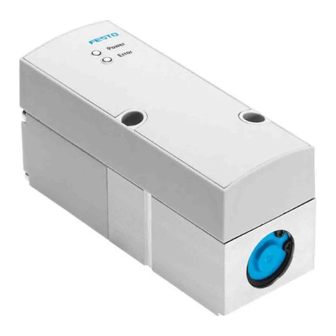
5 Product Overview
5.1 Structure
5.1.1 Product Design
1Pneumatic connection 1:
Input for compressed air
2Exhaust valve
3Drive unit
4Pneumatic connection 2:
Outlet for compressed air
5Pressure gauge
For MSE6-LRE-...-OP: with operat-
or unit
Fig. 1 Product Design
5.2 Function
The product smoothes out pressure fluctuations in pneumatic systems. The elec-
tric drive unit enables the output pressure to be adjusted in the pneumatic
closed-loop controller. The product is controlled via digital input signals. This
determines the direction of rotation of the drive unit and enables the output pres-
sure to be adjusted in an increasing (UP) or decreasing (DOWN) direction. The
pressure control works mechanically.
6 Assembly
1. Observe the flow direction from 1 to 2 è 5.1.1 Product Design.
2. Mount the product using the mounting accessories provided. The opening of
the exhaust valve 2 must not be blocked.
Assembly of module connectors and mounting brackets
è Tab. 1 Documentation on the product.
7 Installation
7.1 Pneumatic Installation
If using fittings with width across flats greater than 24:
• Push the cover cap upwards and remove it.
If using fittings with width across flats up to 24:
• Note the screw-in depth of the connector thread.
Product Screw-in depth
Thread ISO 228
MS6-LRE-1/4 £ 11mm
MS6-LRE-3/8 £ 12mm
MS6-LRE-1/2 £ 14mm
Thread NPT
MS6N-LRE-1/4 £ 10mm
MS6N-LRE-3/8 £ 10.3mm
MS6N-LRE-1/2 £ 13.6mm
Tab. 2 Maximum Screw-in Depth of the Connector Thread
• Screw the connectors into the pneumatic connections using a suitable sealing
material.
7.2 Electrical Installation
WARNING!
Risk of injury due to electric shock.
• For the electrical power supply, use only PELV circuits in accordance with IEC
60204-1/EN 60204-1 (Protective Extra-Low Voltage, PELV).
• Observe the general requirements of IEC 60204-1/EN60204-1 for PELV cir-
cuits.
• Only use voltage sources that ensure a reliable electric separation from the
mains network in accordance with IEC 60204-1/EN 60204-1.
Protection against electric shock (protection against direct and indirect contact) is
guaranteed in accordance with IEC/DIN EN 602041 by using PELV circuits (elec-
trical equipment of machines, general requirements).
Plug Pin Cable colours Function
Plug M12 supply voltage/input signals1)
1 Brown 24VDC supply voltage
2 White 24V input signal UP
3 Blue 0VDC
4 Black 24V input signal DOWN
5 Grey FE - functional earth
1) Tightening torque: £ 0.5Nm
Tab. 3 Pin Allocation of Plug M12
8118305
MS6-LRE
Electrical pressure regulator
8118305
2019-09a
[8118307]
Instructions| Operating
Festo SE & Co. KG
Ruiter Straße 82
73734 Esslingen
Germany
+49 711 347-0
www.festo.com
Plug Pin Cable colours Function
Plug sensor M8 - only MS6-LRE-...-PI/PU1)
1 Brown Not assigned
3 Blue GND/0V
4 Black Analogue output
1) Tightening torque: £ 0.3Nm
Tab. 4 Pin Allocation of Plug Sensor M8
8 Commissioning
The output pressure can be set via the digital inputs on plug M12 or via the oper-
ator unit (MSE6-LRE-...-OP) è 9 Operation.
With simultaneous control, the operator unit has higher priority than the signal
lines at plug M12.
1. Switch on the operating voltage.
2. Close product. Control the drive unit in the direction DOWN.
3. Pressurise the system slowly.
4. Control the product in the direction UP up to the desired output pressure. The
pressure regulation range must not be exceeded
è 13.2 Technical Data, Pneumatic.
Correctly pressurised, the input pressure is 0.5bar higher than the output
pressure.
9 Operation
A new output pressure must always be set in a pressure rising direction. During
control, observe the ratio between the control duration and pause.
The desired output pressure is lower than the current output pressure:
1. Control the product in the direction DOWN until a value of at least 0.3bar
lower than the desired output pressure is reached.
During the control in the direction DOWN, take into account that the product
has a lower exhausting capacity
– The product adjusts faster than the output pressure is reduced.
This may result in the output pressure not corresponding to the desired
control pressure when electrically querying and evaluating the output
pressure. This must be taken into account when exhausting larger initial
volumes.
2. Control the product in the direction UP up to the desired output pressure.
In the event of a power failure, the last setting of the output pressure remains
stored èFail-safe mode.
The pneumatic pressure control is guaranteed.
9.1 With Operator Unit for MSE6-LRE-...-OP
1Display
2Pushbutton [DOWN]
3Edit button
4Pushbutton [UP]
Fig. 2 Operator unit MS6-LRE-...-OP
5Adjustment bar
6Digits
7[kPa], [psi], [bar]
8Segments
9[lock]
Fig. 3 Display MS6-LRE-...-OP
Elements dis-
play
Function Description
Not illu-
minated
Electric drive unit cannot be controlled with pushbutton [DOWN]
2or pushbutton [UP] 4.
Adjustment bar 5
Flashing Electric drive unit can be controlled with pushbutton [DOWN]
2or pushbutton [UP]4.
Elements dis-
play
Function Description
Illuminated Current output pressure is displayed.Digits 6
Flashing Current output pressure has exceeded the pressure regulation
range.
Illuminated Active pressure unit. The output pressure is displayed in these
units.
Not illu-
minated
Pressure unit is inactive.
[kPa]
[psi]
[bar] 7
Flashing Pressure unit can be set.
Segments 8Illuminated Graphical display of the current output pressure, related to the
current value of the pressure regulation range.
Illuminated Active safety lock. For blocking against unauthorised changes to
the output pressure.
Not illu-
minated
Security lock is inactive. Value 0 is set.
[lock] 9
Flashing The security code can be set.
Tab. 5 Elements Display MS6-LRE-...-OP
Overview of Menu Structure
Fig. 4 Overview of Menu Structure
RUN Mode
The default state of the product is called RUN mode. It indicates the current out-
put pressure.
Change from EDIT mode to RUN mode:
– Press EDIT button for 3s or
– Expiration of monitoring time/timeout of 75 s
EDIT Mode
Adjust output pressure and pressure unit:
1. Press the EDIT button 3.
Only when the safety lock is activated:
– The display element [lock] 9flashes
– Press the [DOWN] 2 pushbutton or the [UP] 4 pushbutton until the
selected security code is set.
– To confirm, press the Edit button 3. If the correct entry is made, the
safety lock is released. If an incorrect entry is made, the safety lock
remains in effect. The unit returns to RUN mode. The procedure must be
repeated.
2. The adjustment bars 5 flash. Press the [DOWN] pushbutton or the [UP] push-
button until the desired output pressure is set. Exceeding the pressure regu-
lation range is possible and is indicated by a flashing value in the display.
3. Confirm with Edit button
4. The display elements [kPa], [psi] or [bar] 7 flash. Set the desired pressure
unit with the [DOWN] and [UP] pushbuttons.
5. Confirm with Edit button
6. The display element [lock] flashes. Use the [DOWN] pushbutton or the [UP]
pushbutton to set the desired security code (0…1999). The value 0 deactiv-
ates the safety lock.
7. Confirm with Edit button. The product is back in RUN mode.
9.2 Resetting MS6-LRE-...-OP to Factory Settings
This procedure can also be performed if the security code does not exist.
By resetting to the factory settings, the current settings are lost.
1. Switch off operating voltage.
2. Press the [DOWN] pushbutton, [UP] pushbutton and Edit button simultan-
eously. Switch on the operating voltage again.
10 Maintenance
10.1 Cleaning
1. Switch off energy sources:
– Operating voltage
– Compressed air
2. Clean the outside of the product as required. Approved cleaning agents are
soap solutions (max. +50°C), petroleum ether and all non-abrasive cleaning
agents.
11 Disassembly
1. Switch off energy sources
– Operating voltage
– Compressed air
2. Separate the applicable connections from the product.
12 Disposal
ENVIRONMENT!
Send the packaging and product for environmentally sound recycling in accord-
ance with the current regulations èwww.festo.com/sp.
13 Technical Data
13.1 Technical Data, Mechanical
MS6-LRE-…-D5-…-D6-…-D7-…-D8-…
Mounting position Any
Control time at 25 °C [s] £90
Temperature
Environment [°C] 0…+50
Medium [°C] 0…+50
Immission/Emission
Degree of protection IP65
Immunity to interference EN 61000-6-2:2005
Interference emission EN 61000-6-4:2006 + A1:2010
Vibration/shock resistance
Vibration resistance Severity level 2 as per EN 60068
Shock resistance Severity level 2 as per EN 60068
Tab. 6 Technical Data, Mechanical
Type of Severity Level (SL)
Vibration load
Frequency range [Hz] Acceleration [m/s2] Deflection [mm]
SG1 SG2 SG1 SG2 SG1 SG2
2…8 2…8 – – ±3.5 ±3.5
8…27 8…27 10 10 – –
27…58 27…60 – – ±0.15 ±0.35
58…160 60…160 20 50 – –
160…200 160…200 10 10 – –
Shock load
Acceleration [m/s2] Duration [ms] Shocks per direction
SG1 SG2 SG1 SG2 SG1 SG2
±150 ±300 11 11 5 5
Continuous shock load
Acceleration [m/s2] Duration [ms] Shocks per direction
± 150 6 1000
Tab. 7 Type of Severity Level (SL)
13.2 Technical Data, Pneumatic
MS6-LRE-…-D5-…-D6-…-D7-…-D8-…
Ratio control duration:pause 1:3
Operating pressure
Input pressure [MPa] 0.08…2
[bar] 0.8…20
Pressure regulation range1) [MPa] 0.03…0.4 0.03…0.7 0.05…1.2 0.05…1.6
[bar] 0.3…4 0.3…7 0.5…12 0.5…16
Medium
Operating medium Compressed air according to ISO 8573-1:2010 [7:4:4]
Inert gases
1) If the pressure regulation range is exceeded, the output value may increase proportionally.
Tab. 8 Technical Data, Pneumatic
13.3 Technical Data, Electrical
MS6-LRE-…-D5-…-D6-…-D7-…-D8-…
Nominal operating voltage [VDC] 24
MS6-LRE-…-D5-…-D6-…-D7-…-D8-…
Permissible voltage fluctu-
ations
[%] ±10
Current consumption [A] £3.5 at 24 VDC
Outputs
Analogue with MS6-LRE-…-
PU
[V] 0…10
Analogue for MS6-LRE-…-PI [mA] 4…20
Inputs
Version Inputs According to IEC 61131-2, no galvanic isolation
Tab. 9 Technical Data, Electrical

Other Festo Controllers manuals

Festo SPC200 Series User manual

Festo

Festo SPC200 Series User manual

Festo EPCO-16 User manual

Festo

Festo EPCO-16 User manual

Festo MS2-LFR Parts list manual

Festo

Festo MS2-LFR Parts list manual

Festo CMMP-AS-***-M0 Series Operating and installation instructions

Festo

Festo CMMP-AS-***-M0 Series Operating and installation instructions

Festo VPPM-6TA-L-1-F-0L10H User manual

Festo

Festo VPPM-6TA-L-1-F-0L10H User manual

Festo CMMS-AS G2 Series User manual

Festo

Festo CMMS-AS G2 Series User manual

Festo SEC-AC-305 Operating and installation instructions

Festo

Festo SEC-AC-305 Operating and installation instructions

Festo LFR-B Series User manual

Festo

Festo LFR-B Series User manual

Festo VIFB16 Series User manual

Festo

Festo VIFB16 Series User manual

Festo CECC-X-M1 series Parts list manual

Festo

Festo CECC-X-M1 series Parts list manual

Festo Controller CECC User manual

Festo

Festo Controller CECC User manual

Festo VMPA-B8-R Series User manual

Festo

Festo VMPA-B8-R Series User manual

Festo SPC200 Series User manual

Festo

Festo SPC200 Series User manual

Festo VPPM C1 Series User manual

Festo

Festo VPPM C1 Series User manual

Festo VEAB User manual

Festo

Festo VEAB User manual

Festo CMMS-ST-C8-7 Guide

Festo

Festo CMMS-ST-C8-7 Guide

Festo CMMS-ST Series User manual

Festo

Festo CMMS-ST Series User manual

Festo CMMP-AS-***-M3 Series Operating and installation instructions

Festo

Festo CMMP-AS-***-M3 Series Operating and installation instructions

Festo EduTrainer 571849 User manual

Festo

Festo EduTrainer 571849 User manual

Festo CDSA-D1-VX User manual

Festo

Festo CDSA-D1-VX User manual

Festo CPX-CEC-C1-V3 User manual

Festo

Festo CPX-CEC-C1-V3 User manual

Festo VPPM-...TA-L Series User manual

Festo

Festo VPPM-...TA-L Series User manual

Festo CP-FB11-E Owner's manual

Festo

Festo CP-FB11-E Owner's manual

Festo CPX-CMAX Operating and installation instructions

Festo

Festo CPX-CMAX Operating and installation instructions

Popular Controllers manuals by other brands

Episode EVC-100R owner's manual

Episode

Episode EVC-100R owner's manual

ELPRO ULTIMA LLC-2 operating manual

ELPRO

ELPRO ULTIMA LLC-2 operating manual

Vimar Elvax EKKO ART 200D Installation and operation manual

Vimar

Vimar Elvax EKKO ART 200D Installation and operation manual

Contemporary Research ICC1-232 product manual

Contemporary Research

Contemporary Research ICC1-232 product manual

Autonics TZ Series product manual

Autonics

Autonics TZ Series product manual

Henry Engineering MIXER MATE manual

Henry Engineering

Henry Engineering MIXER MATE manual

Magnimage MIG-CL9600 Series user manual

Magnimage

Magnimage MIG-CL9600 Series user manual

White WHI-SK20PPHS2 manual

White

White WHI-SK20PPHS2 manual

Smartgen HGM410E user manual

Smartgen

Smartgen HGM410E user manual

INVT SV-DA200 Series Operation manual

INVT

INVT SV-DA200 Series Operation manual

Siemens RLU2 Series operating instructions

Siemens

Siemens RLU2 Series operating instructions

Zhiyun MasterEye VC100 user guide

Zhiyun

Zhiyun MasterEye VC100 user guide

CBM LUMIX user manual

CBM

CBM LUMIX user manual

Halma ALICAT SCIENTIFIC PC quick start guide

Halma

Halma ALICAT SCIENTIFIC PC quick start guide

Mircom OpenBAS-LC-NX12R installation manual

Mircom

Mircom OpenBAS-LC-NX12R installation manual

Hitachi ATW-YCC-03 Installation and operation manual

Hitachi

Hitachi ATW-YCC-03 Installation and operation manual

Allen-Bradley PowerFlex 700S quick start

Allen-Bradley

Allen-Bradley PowerFlex 700S quick start

Tense DT-96EM quick start guide

Tense

Tense DT-96EM quick start guide

manuals.online logo
manuals.online logoBrands
  • About & Mission
  • Contact us
  • Privacy Policy
  • Terms and Conditions

Copyright 2025 Manuals.Online. All Rights Reserved.