manuals.online logo
Brands
  1. Home
  2. •
  3. Brands
  4. •
  5. Festo
  6. •
  7. DC Drive
  8. •
  9. Festo DFPD-Series User manual

Festo DFPD-Series User manual

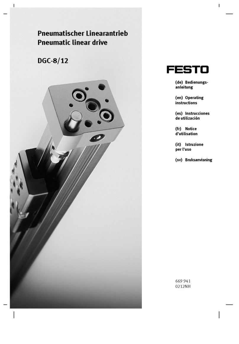
Quarter-turn actuator
DFPD-700 ... 2300
Festo AG & Co. KG
Ruiter Straße 82
73734 Esslingen
Germany
+49 711 347-0
www.festo.com
Operating instructions
(Translation of the original instructions)
8079454
2017-10
[8079456]
Quarter turn actuator DFPD-700 … 2300 English...........................
1 About this document
This document describes the use of the above-mentioned product.
1.1 Further applicable documents
– Certification documents
– Operating conditions EX
For all available product documentation èwww.festo.com/pk
1.2 Target group
The document is targeted towards persons who mount and operate the product.
It is additionally targeted towards individuals who are entrusted with the planning
and application of the product in a safety-related system.
2 Safety
General safety information
– The product may only be used in its original status without unauthorized modi
fications.
– Only use the product if it is in perfect technical condition.
– Take the ambient conditions into consideration at the location of use. Corrosive
environments reduce the service life of the product.
– Observe product labelling.
– Prior to all work, switch off compressed air supply and secure it against acci
dental restarting.
– Exhaust actuator prior to mounting, installation and dismantling.
Operating medium
– Only use compressed air in accordance with the specifications èTechnical data.
– Use only unlubricated compressed air under normal conditions. Once the
product has been used with lubricated compressed air, it must continue to be
operated with compressed air only.
– Protect the device from pressure fluctuations. Use overpressure valves and
pressure regulators.
Return to Festo
Hazardous substances can endanger the health and safety of personnel and cause
damage to the environment. To prevent hazards, the product should only be re
turned upon explicit request by Festo.
– Consult your regional Festo contact.
– Complete the declaration of contamination and attach it to the outside of
the packaging.
– Comply with all legal requirements for handling hazardous substances and con
veying dangerous goods.
3 Intended use
The DFPD quarter turn actuator is intended to actuate process valves, such as ball
valves and butterfly valves with a rotation angle from 0° (valve closed) to 180°
(depending on design).
Note
The operating torque of the actuator must not be higher than the maximum
permissible torque listed in ISO 5211 related to the size of the mounting flange
and coupling.
4 Additional information
– Accessories èwww.festo.com/catalogue
– Spare parts èwww.festo.com/spareparts
– Documents and literature èwww.festo.com/sp
5 Service
 Consult your regional Festo contact if you have technical questions
èwww.festo.com.
6 Product overview
6.1 Configuration
1234
5
6
aB aA
8
7
9
aJ
aC
1Mounting thread for limit switch or
position sensor
2Transmission shaft (shaft groove
shows the process valve position –
here closed)
3Mounting thread for pneumatic
NAMUR switching valve
4Mounting thread for coding pin
5Compressed air supply port (4)
6Mounting thread for pneumatic
NAMUR switching valve
7Mounting thread for coding pin
8Compressed air supply port (2)
9Threaded hole for transport lugs
(DFPD-2300)
aJ End-position adjustment on both
sides
aA Mounting thread for process valve
to ISO 5211
aB Coupling for process valve
aC Leakage slot
Fig. 1
A shaft is guided outward on both sides through the housing. Through this,
the reaction torque is transmitted to a process valve (èFig. 1, aB ) and, if applic
able, a limit switch or position sensor (èFig. 1, 2).
The end stops can be adjusted in the range ± 5° through the end-position adjust
ment on both sides (èFig. 1, 9).
6.2 Product variants and type code
Fig. 2 explains selected product characteristics that are necessary
to understand the instructions.
Description of the complete type code: èwww.festo.com/catalogue.
Characteristic Value Description
Type code DFPD Quarter turn actuator
System of units –
N
Metric
Imperial
Size 700, 900, 1200,
2300
Swivel angle 90, 180 Swivel angle specification in [°]
Closing direction L
R
Closes to the left
Closes to the right
Mode of operation D
S
Double-acting
Single-acting
Spring configuration –, 20, 25, 30, 35,
40, 45, 50, 55, 60
Not for double-acting drive,
for connection pressure with single-acting drive
Flange hole pattern 1 F10, F12, F14 Flange hole pattern according to ISO 5211
Flange hole pattern 2 F12, F16 Flange hole pattern according to ISO 5211
Temperature range T4, T5, T6 èTechnical data
Fig. 2
7 Function
The piston movement of the DPFD is converted through a rack & pinion kinematics
(rack and pinion principle) into a swivel motion of the transmission shaft.
– Single-acting quarter turn actuators: Return is
through spring force.
Fig. 3
– Double-acting quarter turn actuators: Through
pressurising and exhausting of the cylinder cham
bers, the shaft turns back and forth.
Fig. 4
Symbol on the rating plate
Type code Mode of operation Symbol
DFPD-...-RD-...
DFPD-...-LD-...
Double-acting
Closes to the right / left
DFPD-...-RS-... Single-acting (spring return)
Closes to the right
DFPD-...-LS-... Single-acting (spring return)
Closes to the left
Fig. 5
8 Conveying and storage
Warning
Danger of crushing! Danger of shearing!
The product without accessories weighs up to 80 kg, depending on the product
version.
Body parts can be crushed or severed if the product falls.
 Use appropriate load handling equipment.
 For DFPD-2300: Use additional threaded holes (èFig. 1, 9) for transport lugs.
 When dispatching used products: Comply with all legal requirements for hand
ling hazardous substances and conveying dangerous goods.
For return to Festo èChapter 2.
 Remove all attachments.
 Store the product in a cool, dry, UV-protected and corrosion-protected environ
ment. Ensure that storage times are kept to a minimum.
9 Mounting and installation
Note
Mounting and installation should only be carried out by qualified personnel.
9.1 Mounting without adapter bridge
1. Prepare process valve.
– Adjust the switching shaft of the process valve
so that the desired operating method for open
ing and closing is implemented.
2. Place the quarter turn actuator on the switching
shaft of the process valve. The square of the pro
cess valve must sit in the coupling of the quarter
turn actuator (èFig. 1, aB ) without tilting.
3. Fasten the quarter turn actuator to the connecting
flange of the process valve with 4 corrosion-resist
ant screws and retaining rings (material: CI).
4. Tighten the screws crosswise.
– Tightening torque èFig. 8
Fig. 6
9.2 Mounting with adapter bridge
1. Have suitable adapter bridge and shaft extension
ready.
– Accessories èwww.festo.com/catalogue
2. Mount the adapter bridge (èFig. 7, 1)
to the quarter turn actuator.
– Align studs of the adapter bridge lengthwise
to the actuator.
– Align open side of the adapter bridge
on the process valve.
– Tighten screws, but not yet fully tight.
3. Prepare process valve.
– Adjust the switching shaft of the process valve
so that the desired operating method for open
ing and closing is implemented.
4. Insert shaft extension (èFig. 7, 2). The square
of the shaft extension must sit in the coupling of
the quarter turn actuator (èFig. 1, aB ) without
tilting.
5. Place the quarter turn actuator with adapter
bridge and shaft extension onto the switching
shaft of the process valve. The square of the pro
cess valve must sit in the coupling of the shaft
extension without tilting.
6. Mount the adapter bridge to the connecting flange
of the process valve with 4 corrosion-resistant
screws and retaining rings (material: CI).
7. Tighten the screws at both the actuator and
process valve crosswise.
– Tightening torque èFig. 8
Fig. 7
1
2
Flange type F10 F12 F14 F16
Tightening torque [Nm] 46 … 50 80 … 84 190 … 200 370 … 390
Fig. 8
9.3 Pneumatic port
Single-acting quarter turn actuators
Prevent corrosive atmosphere in spring space. In a corrosive atmosphere,
use a rebreather block.
 Mount a filter element to the exhaust port 4 (A) to prevent ingress of dirt.
Type code Compressed
air supply port
Effect
DFPD-...-RS-...,
DFPD-...-LS-...
2Air supply; always connected
4Pressurisation of spring space
Fig. 9
Double-acting quarter turn actuators
Type code Compressed
air supply port
Effect
DFPD-...-RD-... 2 Air supply direction of rotation anti-clockwise1)
4Air supply direction of rotation clockwise1)
DFPD-...-LD-... 2 Air supply direction of rotation clockwise1)
4Air supply direction of rotation anti-clockwise1)
1) Viewed from the connection point of the accessory
Fig. 10
10 Commissioning
Note
Commissioning should only be carried out by qualified personnel.
Prerequisites
– The actuator is fully mounted and connected.
Commissioning the actuator
1. Pressurise actuator slowly.
2. Check correct function at low travel speed.
– Direction of rotation of actuator
– Process valve position
11 Malfunctions
Note
Repairs to the product are not permissible. In the event of malfunctions or failure,
replace the product and let Festo know about the failure. Return defective products
to Festo.
Malfunction Possible cause Remedy
Actuator does not move in
the desired direction
Compressed air supply ports
connected incorrectly
 Correct the tubing connection
Fig. 11
12 Maintenance
With intended use, the product is maintenance-free.
13 Dismounting
Note
Disassembly only by qualified personnel.
13.1 Disassembly
1. Switch off the energy supply (compressed air, electricity)
2. Loosen the pneumatic connections.
3. Remove external attachments.
4. Loosen the mounting screws of the actuator at the process valve and remove
the actuator.
13.2 Replacement of spring package
1
2
3
4
5
1Screws
2Cover
3Seal
4Springs
5End position screws
Fig. 12
Requirements
– Mounting position is vertical. Actuator is secured against tilting.
– Actuator is removed èChapter 13.1.
1. Unscrew end position screws (èFig. 12, 5).
– Actuator is in neutral position
2. Loosen screws (èFig. 12, 1) crosswise until the gap width is reached.
èCover (èFig. 12, 2) is no longer under spring force. The gap width
between cover and actuator is 6 mm.
Warning
Risk of injury due to unexpected movement of components.
A defective spring package can result in the cover remaining under pressure
while it is being dismounted.
If the gap width exceeds the specified value, stop dismounting and dispose of
the actuator èChapter 14.
3. Unscrew screws completely.
4. Remove cover.
èSpring package can now be replaced.
5. Remove springs.
6. Insert new springs in the desired configuration èChapter 13.3.
7. Mount cover.
– Observe correct position of the seal (èFig. 12, 3).
8. Insert screws and tighten them crosswise.
– Tightening torque: èFig. 13
Actuator Diameter Tightening torque [Nm]
DFPD-700 M10 40
DFPD-900 M12 65
DFPD-1200 M14 75
DFPD-2300 M16 120
Fig. 13
13.3 Configuration of spring package
Configuration of the spring package differs, depending on the size.
3
12
1Left
2Right
3Spring position
Fig. 1
Spring
configuration
Spring position Number
of springs
Left Right
[]   0
[20] 25 25 4
[25] 25 246 5
[30] 246 246 6
[35] 246 1346 7
[40] 1346 1346 8
[45] 1346 13456 9
[50] 13456 13456 10
[55] 13456 123456 11
[60] 123456 123456 12
Fig. 2
14 Disposal
 Observe the local regulations for environmentally friendly disposal.
 Dispose of the product in an environmentally friendly manner. When doing this,
also take residual media into account (potential recycling of hazardous waste).
15 Technical data
DFPD-... DFPD DFPD-...-T4 DFPD-...-T6
Standard connection to the process valve ISO 5211
Cushioning None
Mounting position Any
Design Rack and pinion principle
Valve connection conforms to standard VDI/VDE 3845 (NAMUR)
Swivel angle
DFPD-...-700 [°] 0…180
DFPD-...-900
DFPD-...-1200
DFPD-...-2300
[°] 0…90
End position adjustment range 0° [°] ± 5
End position adjustment range
90° / 180°
[°] ± 5
Operating pressure [bar] 2…8 3…8 3…8
Nominal operating pressure
DFPD-...-RD, DFPD-...-LD
DFPD-...-...S-20
DFPD-...-...S-25
DFPD-...-...S-30
DFPD-...-...S-35
DFPD-...-...S-40
DFPD-...-...S-45
DFPD-...-...S-50
DFPD-...-...S-55
DFPD-...-...S-60
[bar]
[bar]
[bar]
[bar]
[bar]
[bar]
[bar]
[bar]
[bar]
[bar]
5.5
2.0
2.5
3.0
3.5
4.0
4.5
5.0
5.5
6.0
Operating medium Compressed air according to ISO8573-1:2010
[7:4:4]
Note on the operating medium Pressure dew point at least 10 °C below outside
temperature, lubricated operation possible
(required in further operation)
Ambient temperature [°C] 20 … +80 0 … +150 50 … +60
CE marking (declaration of conformity
èwww.festo.com/sp)
In accordance with EU Explosion Protection
Directive (ATEX)1)
Material
Housing Anodised wrought aluminium alloy
Cover Coated die-cast aluminium
Shaft Steel, nickel-plated
Stainless steel (only R3 variant)
Screws Stainless steel
Seal NBR FPM FVMQ
1) Take into account certification-specific documentation èwww.festo.com/sp
Fig. 3

Other manuals for DFPD-Series

5

This manual suits for next models

3

Other Festo DC Drive manuals

Festo DGO-xxx-A-B series User manual

Festo

Festo DGO-xxx-A-B series User manual

Festo DRRD-12 User manual

Festo

Festo DRRD-12 User manual

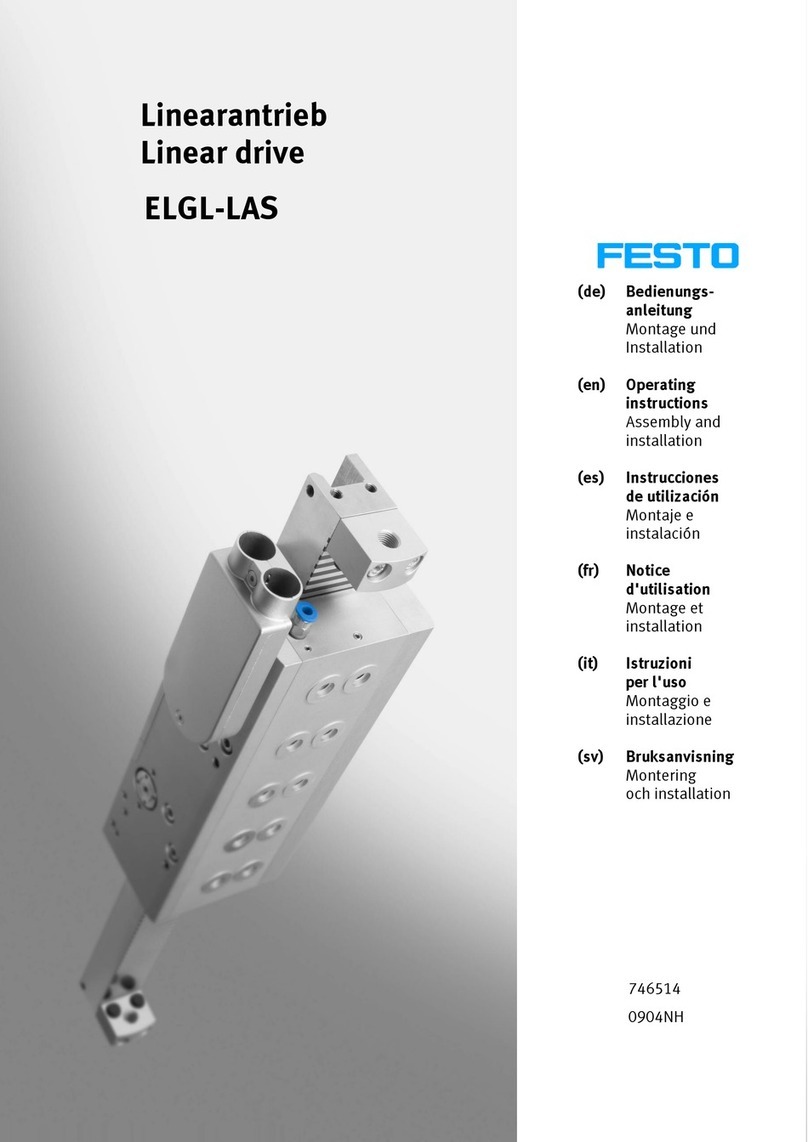
Festo ELGL-LAS User manual

Festo

Festo ELGL-LAS User manual

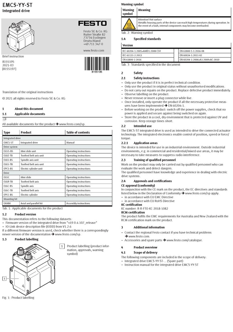
Festo EMCS-ST User manual

Festo

Festo EMCS-ST User manual

Festo DLGF User manual

Festo

Festo DLGF User manual

Festo DAPS..R..-F Series User manual

Festo

Festo DAPS..R..-F Series User manual

Festo FKP Series User manual

Festo

Festo FKP Series User manual

Festo EGC-50-TB Parts list manual

Festo

Festo EGC-50-TB Parts list manual

Festo DDLI-25 User manual

Festo

Festo DDLI-25 User manual

Festo DFPI-***-***-ND2P-E-P-G2 User manual

Festo

Festo DFPI-***-***-ND2P-E-P-G2 User manual

Festo EMCS-ST User manual

Festo

Festo EMCS-ST User manual

Festo DGC-HD Series User manual

Festo

Festo DGC-HD Series User manual

Festo Type SLM-Series-KF-A User manual

Festo

Festo Type SLM-Series-KF-A User manual

Festo ESBF-BS-32 Parts list manual

Festo

Festo ESBF-BS-32 Parts list manual

Festo EMCA-EC-67 CO Series Operating and installation instructions

Festo

Festo EMCA-EC-67 CO Series Operating and installation instructions

Festo EMCA-EC-67-DIO Series Parts list manual

Festo

Festo EMCA-EC-67-DIO Series Parts list manual

Festo DFPD-HD S Series User manual

Festo

Festo DFPD-HD S Series User manual

Festo DNCM POT Series User manual

Festo

Festo DNCM POT Series User manual

Festo DFPI-***-ND2P-C1V-***-A User manual

Festo

Festo DFPI-***-ND2P-C1V-***-A User manual

Festo ERMS Parts list manual

Festo

Festo ERMS Parts list manual

Festo DSM-6 User manual

Festo

Festo DSM-6 User manual

Festo DFPI-...D2P-C1V-NB3P series User manual

Festo

Festo DFPI-...D2P-C1V-NB3P series User manual

Festo DFPI Series User manual

Festo

Festo DFPI Series User manual

Festo EMCA-EC-67 CO Series Reference guide

Festo

Festo EMCA-EC-67 CO Series Reference guide

Popular DC Drive manuals by other brands

Rockwell Automation PowerFlex 7000 instructions

Rockwell Automation

Rockwell Automation PowerFlex 7000 instructions

SOMFY Oximo 40 io instructions

SOMFY

SOMFY Oximo 40 io instructions

VERITAS HSP 157 manual

VERITAS

VERITAS HSP 157 manual

SOMFY Sonesse 28 WireFree RTS Li-ion instructions

SOMFY

SOMFY Sonesse 28 WireFree RTS Li-ion instructions

SOMFY Altus RTS installation guide

SOMFY

SOMFY Altus RTS installation guide

Afag BF10 Translation of original operating instructions

Afag

Afag BF10 Translation of original operating instructions

Ketterer Drive System 3062 Assembly instructions

Ketterer

Ketterer Drive System 3062 Assembly instructions

LS ELECTRIC LSLV-L100 Series user manual

LS ELECTRIC

LS ELECTRIC LSLV-L100 Series user manual

SOMFY Roll Up 28 WireFree RTS instructions

SOMFY

SOMFY Roll Up 28 WireFree RTS instructions

Danfoss VLT 2800 manual

Danfoss

Danfoss VLT 2800 manual

WEG CFW-11 Series Programming manual

WEG

WEG CFW-11 Series Programming manual

Lenze EYF Mounting instructions

Lenze

Lenze EYF Mounting instructions

TECHTOP TOPDRIVE20 Series installation guide

TECHTOP

TECHTOP TOPDRIVE20 Series installation guide

Danfoss VLT AQUA Drive FC 200 instruction manual

Danfoss

Danfoss VLT AQUA Drive FC 200 instruction manual

Moons' MSST5-S user manual

Moons'

Moons' MSST5-S user manual

Eaton Crouse-hinds series Installation & maintenance information

Eaton

Eaton Crouse-hinds series Installation & maintenance information

NI P7000 Series Getting started

NI

NI P7000 Series Getting started

Danfoss VLT AutomationDrive FC 360 operating guide

Danfoss

Danfoss VLT AutomationDrive FC 360 operating guide

manuals.online logo
manuals.online logoBrands
  • About & Mission
  • Contact us
  • Privacy Policy
  • Terms and Conditions

Copyright 2025 Manuals.Online. All Rights Reserved.