manuals.online logo
Brands
  1. Home
  2. •
  3. Brands
  4. •
  5. Festo
  6. •
  7. Industrial Equipment
  8. •
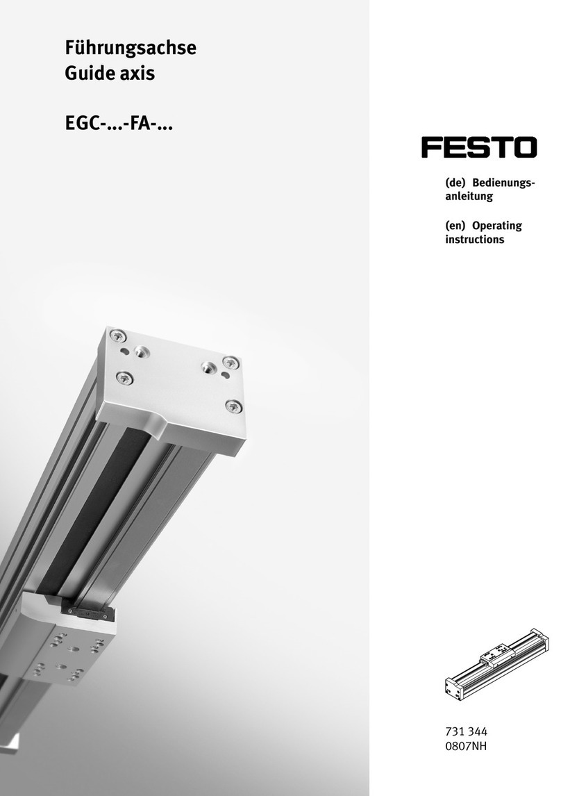
  9. Festo EGC FA Series User manual

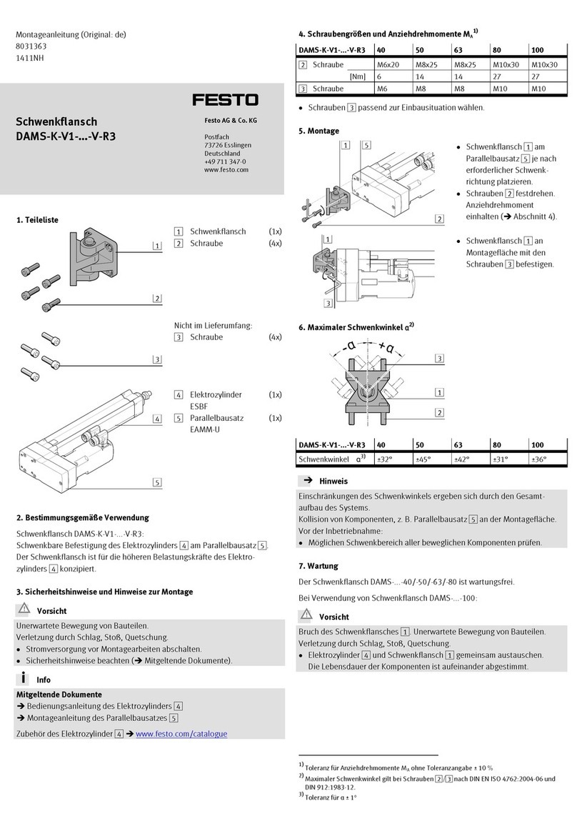
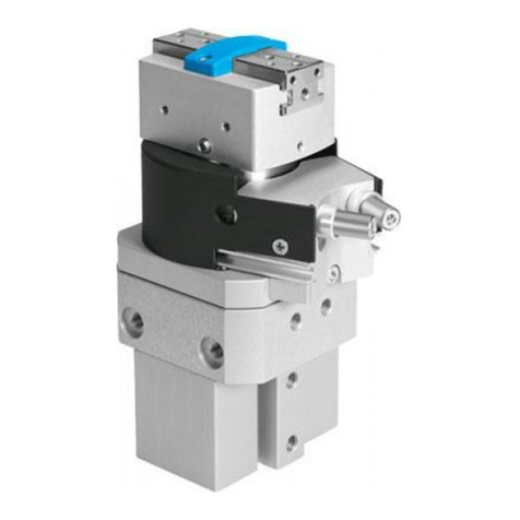
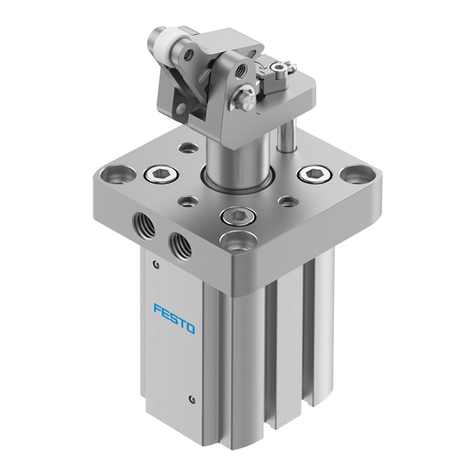
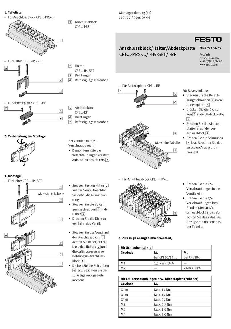
Festo EGC FA Series User manual

Translation of the original instructions
© 2020 all rights reserved to Festo SE & Co. KG
1 Applicable Documents
All available documents for the product èwww.festo.com/sp.
2 Safety
2.1 Safety instructions
– Observe labelling on the product.
– Prior to assembly, installation and maintenance work: Switch off power sup
ply, ensure that it is off and secure it against being switched back on.
– Store the product in a cool, dry, UVprotected and corrosionprotected envir
onment. Ensure that storage times are kept to a minimum.
– Observe tightening torques. Unless otherwise specified, the tolerance
is±20%.
2.2 Intended use
The axis is intended for use in combination with a drive axis for moving payloads
in multiaxis applications (e.g.planar surface gantries).
The axis is only approved for slide operating mode.
Fig. 1 Slide mode
2.3 Training of skilled personnel
Installation, commissioning, maintenance and disassembly should only be con
ducted by qualified personnel.
3 Further information
– Accessories èwww.festo.com/catalogue.
– Spare parts èwww.festo.com/spareparts.
4 Service
Contact your regional Festo contact person if you have technical questions
èwww.festo.com.
5 Product overview
5.1 Function
The slide of the axis follows the movement of the parallel mounted drive axis via
the mechanical coupling. The linear movement of the slide is precisely guided by
the guide. Sensors enable the monitoring of end positions, reference position and
intermediate position.
5.2 Product design
1End cap
2Guide rail
3Cover profile
4Guide lubrication point
5Threaded and centring hole for
attachment element
6Threaded hole for switch lug
7Slide
8Slot for sensor
9Slot for profile mounting, slot nut
and sensor bracket
10 Slot for slot nut
11 Profile
12 Threaded hole for foot mounting
Fig. 2 Product design EGCFA
6 Transport and storage
NOTICE!
Unexpected and unbraked movement of components
• Secure moving components for transport.
Transport and Storage Conditions
– Take product weight into account è 14 Technical data.
Weight>25kg: transport with a suitable hoist (crossbrace) or with two per
sons.
– Take the product centre of gravity into consideration.
– Comply with maximum permitted support clearances when attaching trans
portation aids è 14 Technical data.
– Store and transport the product in its original packaging.
– Store product in a cool, dry, shaded and corrosion protected environment.
– Store product in ambient conditions without oils, greases and degreasing
vapours.
– Ensure short storage times.
7 Assembly
7.1 Safety
WARNING!
Risk of Injury due to Unexpected Movement of Components
For vertical or slanted mounting position: when power is off, moving parts can
travel or fall uncontrolled into the lower end position.
• Bring moving parts of the product into a safe end position or secure them
against falling.
7.2 Unpack product
1. Open packaging.
2. Remove all transport materials (e.g.foils, caps, cardboard boxes)
3. Remove the product from the packaging and place it on the mounting surface.
Comply with maximum permitted support clearances when attaching trans
portation aids è 14.2 Characteristic curves.
4. Dispose of packaging and transport materials è 13 Disposal.
7.3 Fasten axis
High mechanical loads on the mounting connections
If high parallel torques are applied to the drive system at the same time, this
leads to high mechanical loads at the mounting interfaces.
• The foot mountingHPE should only be used in combination with the profile
mountingMUE or the slot nutsNST.
Requirement
– No collision in the movement space of the attachment component with
mounting and sensor components.
– Sufficient space to reach maintenance interfaces.
– Flatness of the mounting surface of 0.05%of the stroke length or max.
0.5mm over the stroke length of the bearing surface.
– Required support points lie within the specified support
distancesè 14.2 Characteristic curves.
– No distortion or bending when installing the product.
1. Select mounting attachments èwww.festo.com/catalogue.
2. Place the mounting attachments on the support points.
8119099
EGC-...-FA
Guide axis
8119099
202001c
[8119101]
Instructions| Operating
Festo SE & Co. KG
Ruiter Straße 82
73734 Esslingen
Germany
+49 711 3470
www.festo.com
3. Tighten retaining screws.
Observe max. tightening torque and max. screwin depth.
In the case of planar and 3dimensional gantries, pay attention to parallelism,
product height and alignment of the axes.
For additional information, contact your local Festo Service.
Profile mountingMUE
(EGC-...-...M)
Slot nutNST For mount-
ing slot
(EGC-...-...Y)
Foot mountingHPE
(EGC-...-F)
Mounting via profile groove Mounting via profile groove Mounting via thread
Tab. 1 Overview of mounting components
EGC-FA
Size 70 80 120 185
Profile mountingMUE
Screw Instruction manual èwww.festo.com/sp.
Slot nutNST
Screw (side/bottom) M5 M5 M6 M6
max. screwin depthtmax [mm] 6 6 12 12
Foot mountingHPE
Screw M5 M5 M8 M10
max. tightening torque [Nm] 5.9 5.9 24 47
max. screwin depthtmax [mm] 10 10 16 20
Tab. 2 Information on mounting attachments
7.4 Mounting the attachment component
Collision-free Flat Centre of gravity
and tilting
moment
Max. screw-in
depth
Tab. 3 Requirements for attachment component
Requirement
– No collision in the movement space of the attachment component with
mounting and sensor components.
– Flatness of the mounting surface of the attachment component of 0.01mm
above the slide surface.
– Position of the centre of gravity and tilting moment (force F parallel to the axis
of motion) of the attachment component centrally on the slide and close to
the slide surface (short lever arm a).
– The maximum screwin depth of the retaining screws is not exceeded.
1. Select accessories èwww.festo.com/catalogue.
2. Place centring components in centring holes.
3. Position the attachment component on the slide.
4. Tighten retaining screws.
Observe max. tightening torque and max. screwin depth.
When using an additional external guide, ensure exact parallelism and alignment
of the axes and guide.
Recommendation: use guide fixings with tolerance compensation.
Direct mounting
Mounting via thread
Tab. 4 Overview of attachment component
EGC-FA
Size 70 80 120 185
Direct mounting
Screw (side/top) M5 M5; M6 M6; M8
Max. tightening torque [Nm] 5.9 5.9; 9.9 9.9; 24
Max. screwin depthtmax [mm] 8.4 9.5 10 15
Centring (bore tolerance H7)
Centring pins (side/top) [mm] Æ5–
Centring sleeve (side/top) [mm] – Æ7/Æ9Æ9
Tab. 5 Information on attachment component
7.5 Mounting accessories
Requirement
– No collision in the movement space of the attachment component with
mounting and sensor components.
– Protection against uncontrolled overtravel of the end positions.
– Homing to reference switch or end position.
– Query of end positions or intermediate positions.
– Avoidance of hard impacts at the end positions.
– Prevention of contamination in the slots.
1. Select accessories èwww.festo.com/catalogue.
2. Mount mechanical end position protection:
– Mount shock absorber retainer.
– Mount shock absorber or emergency buffer.
3. Mount the sensor (reference or query):
– Mount the sensor bracket and switch lug (depending on the type of
mounting).
– Mount the sensor.
– Fasten the cable with clips.
4. Mount the slot cover.
Instruction manuals èwww.festo.com/sp.
Profile groove Sensor bracket
– Switch lug: mounting on slide
– Sensor: mounting via profile groove
– Switch lug: mounting on slide
– Sensor bracket: mounting via profile groove
– Sensor: mounting on the sensor bracket
– Protect the sensor from external magnetic or ferritic influences (e.g.min. 10 mm distance to
slot nuts).
– Preferably use hardware limit switches with normally closed function (protection guaranteed
even in case of sensor failure).
– Query switching lug only with inductive sensor.
Instruction manual èwww.festo.com/sp.
Tab. 6 Overview of Sensor Mountings
8 Commissioning
8.1 Safety
WARNING!
Risk of injury due to unexpected movement of components.
• Protect the positioning range from unwanted intervention.
• Keep foreign objects out of the positioning range.
• Perform commissioning with low dynamic response.
8.2 Performing commissioning
Running noises during operation
Identical axes can generate different running noises depending on the paramet
erisation, mode of operation, type of mounting, installation environment and com
ponents.
Requirement
– Mounting of the drive system checked.
– No foreign objects in the movement space of the propulsion system.
– No mechanical overload of the axis and dynamic setpoint deviation not
exceeded (e.g.overrunning the end position) due to force and torque peaks.
• Commissioning of the drive system (e.g. control and homing) èInstruction
manual for drive axis, www.festo.com/sp.
9 Operation
WARNING!
Risk of injury due to unexpected movement of components.
• Protect the positioning range from unwanted intervention.
• Keep foreign objects out of the positioning range.
• Perform commissioning with low dynamic response.
10 Maintenance
10.1 Safety
WARNING!
Unexpected movement of components
Injury due to impact or crushing.
• Before working on the product: secure the slide to prevent unintentional
movement.
CAUTION!
For vertical or slanted mounting position: when power is off, moving parts can
travel or fall uncontrolled into the lower end position.
Injury due to impacts or crushing.
• Bring moving parts of the product into a safe end position or secure them
against falling.
10.2 Cleaning
1. Clean the product with a soft cloth. Do not use aggressive cleaning agents.
2. If necessary, clean the guide rail with a soft lintfree cloth without detergent.
Then apply a thin layer of lubricant to the guide rail.
10.3 Lubrication
Lubrication interval and accessories
NOTICE!
The lubrication interval Sint is dependent on the load acting on the product.
Load factors include e.g.:
• Dusty and dirty environment
•Nominal stroke > 2000mm or < 300mm
•Speed > 2m/s
•Ambient temperature > +40°C
•Service age of product > 3years
• Travel profile matches triangular operation (frequent acceleration and brak
ing)
If one of these factors applies:
• Halve lubrication interval Sint.
If several factors apply at the same time:
• Divide service interval Sint by four.
Lubrication Recirculating ball bearing guide Guide rail
Lubrication interval – Calculate the comparative loading factor fv
using the formula for combined loads
è Tab. 10 General data,
EGC70/80/120/185FA.
– Lubrication intervals Sint as a function of the
load comparison factor fv can be taken from
the diagram.
If required, e.g.if the
grease layer is insuffi
cient.
Accessories èwww.festo.com/spareparts
Lubrication point Lubrication hole Surface
Lubricant Roller bearing grease LUBKC1
Lubrication Recirculating ball bearing guide Guide rail
Pressure grease gun with pinpoint nozzle LUB1, 647958Grease gun
– Lubrication adapter, axial output,
LUB1TRI, 647959
– Lubrication adapter, radial output,
LUB1TRL, 647960
–
Tab. 7 Overview of lubrication intervals and accessories
Lubricate guide
Recirculating ball bearing guide (EGC-…-GK/GV)
Lubrication hole, both sides
Grease quantity per lubricating hole:
EGC ... GK/GV (size), 2 lubrication holes, lateral (left and right)
– 70: 0.3g
– 80: 0.6g
– 120: 1.2g
– 185: 3.6g
Tab. 8 Lubrication overview
1. Inject lubricant into all lubrication holes.
2. During the lubrication process, travel the entire distance in order to distribute
the lubricant evenly inside the machine.
11 Malfunctions
11.1 Fault clearance
WARNING!
Unexpected movement of components
Injury due to impact or crushing.
• Before working on the product: secure the slide to prevent unintentional
movement.
WARNING!
Risk of injury due to unexpected movement of components.
• Protect the positioning range from unwanted intervention.
• Keep foreign objects out of the positioning range.
• Perform commissioning with low dynamic response.
CAUTION!
For vertical or slanted mounting position: when power is off, moving parts can
travel or fall uncontrolled into the lower end position.
Injury due to impacts or crushing.
• Bring moving parts of the product into a safe end position or secure them
against falling.
Malfunction Possible cause Remedy
Torsional stresses – Install axis without tension. Note the flat
ness of the contact surface
è 7.3 Fasten axis.
– Change the layout of the attachment com
ponent (e.g.payload).
– Align axes parallel to one another.
Resonance oscillation
of the axis
Change the travel velocity.
Wear on guide – Contact local Festo Service.
– Replace axis èwww.festo.com/catalogue.
Loud running noises,
vibrations or rough
running of the axis
Insufficient lubrication
of guide
Lubricate the guide è 10.3 Lubrication.
Vibrations on the slide Operation at the reson
ant frequency of the
axis
– Change the travel velocity.
– Change the acceleration.
– Increase axis stiffness (e.g.shorter support
distances).
– Change the payload geometry.
Long oscillations of the
profile
The resonant fre
quency from the profile
and useful load are too
low
– Increase axis stiffness (e.g.shorter support
distances).
– Change the payload geometry.
Loads too high Reduce forces and torques. Consider dynamics.Slide does not move
Screws too long for fix
ing the attachment
component (e.g.pay
load)
Observe the screwin depth
è 7.4 Mounting the attachment component.
Overruns the end posi
tion
Sensor does not switch Check sensor, installation and parameterisation.
Tab. 9 Overview of fault clearance
11.2 Repair
– Observe the instructions for dismantling è 12 Disassembly.
– Send axis to Festo repair service.
– Information about spare parts and accessories
èwww.festo.com/spareparts.
12 Disassembly
WARNING!
Unexpected movement of components
Injury due to impact or crushing.
• Before working on the product: secure the slide to prevent unintentional
movement.
WARNING!
Risk of Injury due to Unexpected Movement of Components
For vertical or slanted mounting position: when power is off, moving parts can
travel or fall uncontrolled into the lower end position.
• Bring moving parts of the product into a safe end position or secure them
against falling.
1. Disconnect electrical installations. (if applicable)
2. Remove the attached accessories. (if applicable)
3. Remove the mounted attachment component.
4. Remove the mounted connecting component to the drive axis.
5. Remove the mounting attachments.
6. Observe transport information è 6 Transport and storage.
13 Disposal
Dispose of the product and packaging according to the valid provisions of envir
onmentally sound recycling.
14 Technical data
14.1 Technical data, mechanical
To size the axis, use the PositionDrives engineering software
èwww.festo.com/sp.
EGC-70/80/120/185-FA
Size 70 80 120 185
Design Mechanical axis
Guide Recirculating ball bearing guide
Mounting position Any
Max. velocity
– EGC ... GK 5
– EGC ... GP
[m/s]
5 3
Max. acceleration [m/s2] 50
Ambient temperature [°C] –10…+60
Degree of protection IP40
Max. permissible forces and torques on the slide
EGCGK, EGCGP
Fy [kN] 1.85 3.05 6.89 15.2
Fz [kN] 1.85 3.05 6.89 15.2
Mx [Nm] 16 36 144 529
My [Nm] 51 97 380 1157
Mz [Nm] 51 97 380 1157
EGCGV, EGCGQ
Fy [kN] 1.85 3.05 6.89 15.2
Fz [kN] 1.85 3.05 6.89 15.2
Mx [Nm] 16 36 144 529
My [Nm] 132 228 680 1820
Mz [Nm] 132 228 680 1820
Calculating the load comparison factor
fv
Tab. 10 General data, EGC70/80/120/185FA
EGC-70/80/120/185-FA
EGC-FA
Size 70 80 120 185
Materials
Note on materials RoHScompliant
Contains PWIS
Profile
End cap
Slide
Anodised aluminium
Guide
Screws
Steel
Cover profile Acrylonitrile butadiene styrene
Buffer Nitrile rubber
Weight
Basic weight at 0mm stroke [kg] 1.2 2 7.3 20.8
Additional weight per
1000mm stroke
[kg] 4.2 6.2 15 29
Tab. 11 Materials and weight
14.2 Characteristic curves
Support distance EGC-70/80/120/185-FA
Maximum permissible support distance L (without profile mounting MUE/central
support EAHF) as a function of force Fy/Fz with a maximum deflection of 0.5mm.
Support spacing Force load
Tab. 12 Overview of support spacing and force load
EGC-...-FA
L [mm]
Fy [N]
500 1000 1500 2000 2500 3000 3500 4000
10
20
50
100
200
500
1000
2000
4000
EGC70FA
EGC80FA
EGC120FA
EGC185FA
Fig. 3 Support distances L as a function of force Fy
EGC-...-FA
L [mm]
Fz [N]
500 1000 1500 2000 2500 3000 3500 4000
10
20
50
100
200
500
1000
2000
4000
EGC70FA
EGC80FA
EGC120FA
EGC185FA
Fig. 4 Support distances L as a function of force Fz

Other manuals for EGC FA Series

1

This manual suits for next models

4

Other Festo Industrial Equipment manuals

Festo YXCA User manual

Festo

Festo YXCA User manual

Festo EXCH User manual

Festo

Festo EXCH User manual

Festo STAF-...-P-A-R series User manual

Festo

Festo STAF-...-P-A-R series User manual

Festo ELCC-TB-KF-60 F1 Series Setup guide

Festo

Festo ELCC-TB-KF-60 F1 Series Setup guide

Festo HGPL-B Series User manual

Festo

Festo HGPL-B Series User manual

Festo EXCH-40-...-W Series User manual

Festo

Festo EXCH-40-...-W Series User manual

Festo MPS 8033591 User manual

Festo

Festo MPS 8033591 User manual

Festo CPX-AB-1-7/8-DN User manual

Festo

Festo CPX-AB-1-7/8-DN User manual

Festo YXCS User manual

Festo

Festo YXCS User manual

Festo CPX-F8DE-P User manual

Festo

Festo CPX-F8DE-P User manual

Festo EHPS-16 Parts list manual

Festo

Festo EHPS-16 Parts list manual

Festo HGP A-B Series User manual

Festo

Festo HGP A-B Series User manual

Festo DHWS User manual

Festo

Festo DHWS User manual

Festo Checkbox Compact CHB-C-F Owner's manual

Festo

Festo Checkbox Compact CHB-C-F Owner's manual

Festo YJKP-NGS User manual

Festo

Festo YJKP-NGS User manual

Festo FBS-SUB-9-GS-IB-B User manual

Festo

Festo FBS-SUB-9-GS-IB-B User manual

Festo ELGT-BS User manual

Festo

Festo ELGT-BS User manual

Festo ELGA-BS-KF-70 Setup guide

Festo

Festo ELGA-BS-KF-70 Setup guide

Festo HGPM-xxx-G series User manual

Festo

Festo HGPM-xxx-G series User manual

Festo DNCE User manual

Festo

Festo DNCE User manual

Festo DFPI ND2P-C1V A Series User manual

Festo

Festo DFPI ND2P-C1V A Series User manual

Festo DHPS User manual

Festo

Festo DHPS User manual

Festo DGEA Series User manual

Festo

Festo DGEA Series User manual

Festo EHPS LK Series User manual

Festo

Festo EHPS LK Series User manual

Popular Industrial Equipment manuals by other brands

Tolomatic TC07SS Repair Parts Sheet

Tolomatic

Tolomatic TC07SS Repair Parts Sheet

Power Fist 8885048 user manual

Power Fist

Power Fist 8885048 user manual

Z.I.P.P.ER MASCHINEN ZI-MHK2 user manual

Z.I.P.P.ER MASCHINEN

Z.I.P.P.ER MASCHINEN ZI-MHK2 user manual

Alfalaval Contherm 6X3 instruction manual

Alfalaval

Alfalaval Contherm 6X3 instruction manual

JackRabbit CO-JACK 197+ Owner's/operator's manual

JackRabbit

JackRabbit CO-JACK 197+ Owner's/operator's manual

Cold Jet PR750H user manual

Cold Jet

Cold Jet PR750H user manual

tricab M50 user guide

tricab

tricab M50 user guide

System air SAVE VTC 300 user manual

System air

System air SAVE VTC 300 user manual

Spraying Systems AutoJet VC10 owner's manual

Spraying Systems

Spraying Systems AutoJet VC10 owner's manual

Aero-motive Woodhead BF Series Service manual

Aero-motive

Aero-motive Woodhead BF Series Service manual

Power Tec 71392 owner's manual

Power Tec

Power Tec 71392 owner's manual

Cold Jet COMBI PCS 110 DUAL Operator's manual

Cold Jet

Cold Jet COMBI PCS 110 DUAL Operator's manual

KEBCO COMBINORM instruction manual

KEBCO

KEBCO COMBINORM instruction manual

HIK VISION DS-K3Y501 quick start guide

HIK VISION

HIK VISION DS-K3Y501 quick start guide

aquamundus GreaseShield 1850-F installation guide

aquamundus

aquamundus GreaseShield 1850-F installation guide

systectherm FWT Instructions for installation and use

systectherm

systectherm FWT Instructions for installation and use

Alfalaval Mini City F2 Installation and operating

Alfalaval

Alfalaval Mini City F2 Installation and operating

Alfalaval Pharma-line 1 instruction manual

Alfalaval

Alfalaval Pharma-line 1 instruction manual

manuals.online logo
manuals.online logoBrands
  • About & Mission
  • Contact us
  • Privacy Policy
  • Terms and Conditions

Copyright 2025 Manuals.Online. All Rights Reserved.