Festo EMCA-EC-67 CO Series User manual

Description
FHPP device profile
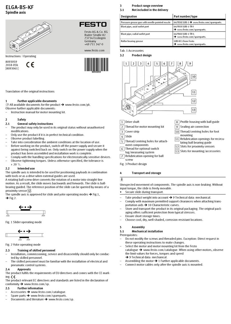
For fieldbus:
– CANopen
– EtherNet/IP
8066844
1611b
[8066846]
EMCA-EC-67-...-CO/-EP
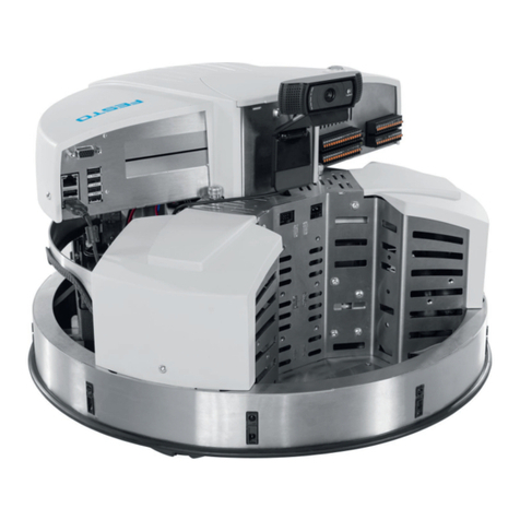
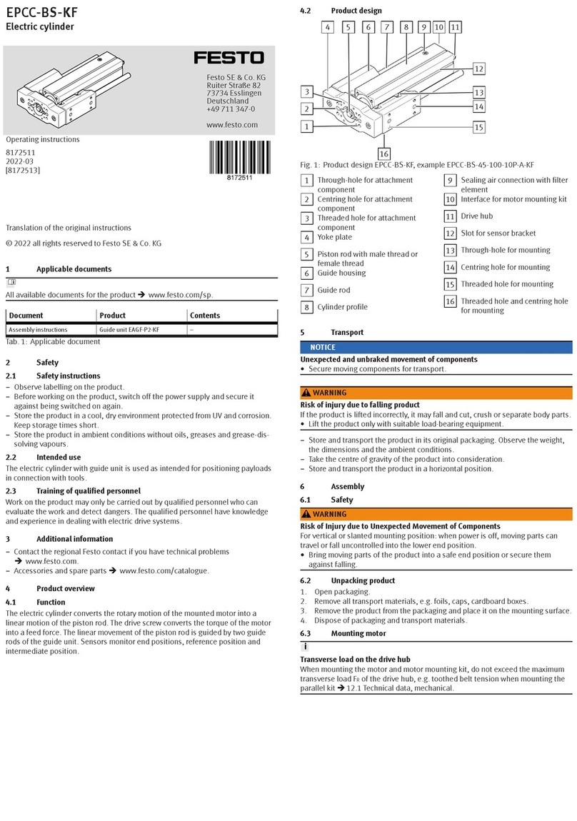
Integrated Drive

EMCA-EC-67-...-CO/-EP
2 Festo – GDCE-EMCA-EC-C-HP-EN – 1611b – English
Translation of the original instructions
GDCE-EMCA-EC-C-HP-EN
CANopen®, CiA®, EtherNet/IP®are registered trademarks of the respective trademark owners in
certain countries.
Identification of hazards and instructions on how to prevent them:
Warning
Hazards that can cause death or serious injuries
Caution
Hazards that can cause minor injuries
Other symbols:
Note
Material damage or loss of function
Recommendations, tips, references to other documentation
Essential or useful accessories
Information on environmentally sound usage
Text designations:
Activities that may be carried out in any order
1. Activities that should be carried out in the order stated
– General lists

EMCA-EC-67-...-CO/-EP
Festo – GDCE-EMCA-EC-C-HP-EN – 1611b – English 3
Table of Contents – EMCA-EC-67-...-CO/-EP
1 FHPP device profile (Festo Handling and Positioning Profile) 15......................
1.1 FHPP overview 15............................................................
1.2 Fieldbus interfaces 16........................................................
1.2.1 CANopen interfaces 16...............................................
2 CANopen 17................................................................
2.1 CiA standards 17............................................................
2.2 CAN bus/CANopen interface of the EMCA 18......................................
2.2.1 CANopen display component 18........................................
2.2.2 CAN bus ports 19...................................................
2.2.3 Termination of the CAN bus (terminating resistor) 20.......................
2.2.4 CAN bus cabling 21..................................................
2.2.5 CAN bus cable 22...................................................
2.3 Configure CANopen participants 22.............................................
2.3.1 Configure EMCA 23..................................................
2.3.2 Commission EMCA with the Festo Configuration Tool (FCT) 26................
2.3.3 Configure CANopen master 26.........................................
2.4 Required digital inputs for operation 27..........................................
2.5 Data interfaces (parameter/firmware) 28.........................................
3 EtherNet/IP with FHPP 29.....................................................
3.1 ODVA standards 29..........................................................
3.2 EtherNet/IP interface of the motor unit 30........................................
3.2.1 EtherNet/IP display components 30.....................................
3.2.2 EtherNet/IP connections 31...........................................
3.2.3 EtherNet/IP copper cabling 31.........................................
3.3 Configuration EtherNet/IP stations 32...........................................
3.3.1 Parameterisation of the Ethernet/IP interface 32..........................
3.3.2 Commissioning with the Festo Configuration Tool (FCT) 32...................
3.3.3 Setting the IP address 32.............................................
3.3.4 Setting the optional use of FPC and FHPP+ 33.............................
3.4 Electronic data sheet (EDS) 33.................................................
4 FHPP 34...................................................................
4.1 FHPP communication 34......................................................
4.1.1 Function 34........................................................
4.1.2 Structure of the FHPP message 35......................................

EMCA-EC-67-...-CO/-EP
4 Festo – GDCE-EMCA-EC-C-HP-EN – 1611b – English
5 FHPP standard data (I/O data) 37..............................................
5.1 FHPP finite state machine (sequence control) 37...................................
5.1.1 “Achieve ready status” status transitions 38..............................
5.1.2 Status transitions “Operation enabled” 40...............................
5.2 Structure of the FHPP standard data (I/O data) 43..................................
5.2.1 Function 43........................................................
5.2.2 Structure of the FHPP message 43......................................
5.2.3 Structure of the FHPP standard data 44..................................
5.3 FHPP control and status data 46................................................
5.3.1 Overview: FHPP control data 46........................................
5.3.2 Overview: FHPP status data 48.........................................
5.3.3 Description: control bytes 50..........................................
5.3.4 Description: status bytes 54...........................................
6 Measuring reference system 60................................................
6.1 Configure dimensional reference system 60.......................................
6.1.1 Dimension reference system for linear drives 61...........................
6.1.2 Dimension reference system for rotative drives 62.........................
6.1.3 Calculation rules for the dimension reference system 63....................
6.1.4 Limit switch LSN/LSP (hardware) 63....................................
6.1.5 Software end position SLN/SLP 63......................................
6.2 Increments 64..............................................................
6.2.1 Encoder increments [EINC] 64..........................................
6.2.2 Interface increments [SINC] 64.........................................
6.3 Factor group (Factor Group) 64.................................................
6.3.1 Exponents 64.......................................................
6.4 Parameters for position determination 66........................................
6.4.1 Conversion factors 66................................................
7 Control via FHPP 67..........................................................
7.1 Establish ready status 69......................................................
7.1.1 Establish ready status 70.............................................
7.2 Cancel travel/positioning task with “Halt” or “Stop” 71..............................
7.2.1 Cancel homing, jog, speed or force/torque mode “Halt” 71..................
7.2.2 Cancel homing, jog, record selection or direct mode with “Stop” 71...........
7.3 Master control and access protection 72.........................................
7.3.1 Master control over the EMCA 72.......................................

EMCA-EC-67-...-CO/-EP
Festo – GDCE-EMCA-EC-C-HP-EN – 1611b – English 5
7.4 Homing mode 73............................................................
7.4.1 Homing 73.........................................................
7.4.2 FHPP parameters: homing 74..........................................
7.4.3 Control homing mode 75..............................................
7.4.4 Diagram: Homing to reference/limit switch 76.............................
7.4.5 Diagram: Homing to stop 77...........................................
7.4.6 Methods of homing 78...............................................
7.5 Jog operation 84.............................................................
7.5.1 FHPP parameters: jog operation 84.....................................
7.5.2 Control jog operation 85..............................................
7.5.3 Diagram: jog mode 86................................................
7.6 Teach mode 87..............................................................
7.6.1 FHPP parameter: Teach mode 87.......................................
7.6.2 Control teach mode 88...............................................
7.6.3 Diagram: teach mode 89..............................................
7.7 Record selection mode 90.....................................................
7.7.1 Overview: Data exchange in the record selection mode 90...................
7.7.2 FHPP parameters: record selection mode 91..............................
7.7.3 Control record selection mode 93.......................................
7.7.4 Control intermediate stop 94..........................................
7.7.5 Delete remaining path 95.............................................
7.7.6 Stroke limit reached 95...............................................
7.7.7 Diagram: Start and stop record 96......................................
7.7.8 Diagram: Interrupt and continue positioning record with Halt
(intermediate stop) 97...............................................
7.7.9 Diagram: Interrupt positioning record with Halt and delete remaining path 98...
7.7.10 Diagram: Positioning mode (point-to-point positioning) 99...................
7.7.11 Diagram: speed mode 100.............................................
7.7.12 Diagram: force/torque mode 101........................................
7.8 Record chaining 102..........................................................
7.8.1 Control record chaining 104............................................
7.8.2 Diagram: record chaining 105...........................................
7.8.3 Diagram: record sequencing with final speed 106...........................
7.8.4 Stroke monitoring 107................................................

EMCA-EC-67-...-CO/-EP
6 Festo – GDCE-EMCA-EC-C-HP-EN – 1611b – English
7.9 Direct operation 109..........................................................
7.9.1 Overview: data exchange in direct operation 109...........................
7.9.2 FHPP parameters: direct operation 110...................................
7.9.3 Control direct operation 112............................................
7.9.4 Control intermediate stop 114..........................................
7.9.5 Delete remaining path 114.............................................
7.9.6 Stroke limit reached 115...............................................
7.9.7 Diagram: Start and stop positioning task 116..............................
7.9.8 Diagram: Interrupt and continue positioning task with Halt (intermediate stop) 117
7.9.9 Diagram: Interrupt positioning task with Halt and delete remaining path 118.....
7.9.10 Diagram: Positioning mode (point-to-point positioning) 119...................
7.9.11 Diagram: speed mode 120.............................................
7.9.12 Diagram: force/torque mode 121........................................
7.9.13 Diagram: Final speed 122..............................................
7.9.14 Stroke monitoring 123................................................
7.10 Flying measurement (position sampling) 125.......................................
8 Monitoring of the drive behaviour 126............................................
8.1 Messages 126...............................................................
8.1.1 Motion complete 127.................................................
8.1.2 Following error 129...................................................
8.1.3 Standstill monitoring 131..............................................
8.1.4 Comparators 133.....................................................
8.2 Protective functions 135.......................................................
8.2.1 Overview: protective functions 135......................................
8.2.2 I2t monitoring 136....................................................
A Festo Parameter Channel (FPC) 138..............................................
A.1 Festo Parameter Channel (FPC) for cyclic data (I/O data) 138..........................
A.1.1 Function 138........................................................
A.2 Enhanced Festo Parameter Channel (EFPC) 139.....................................
A.2.1 Structure of the Enhanced Festo Parameter Channel (EFPC) 139...............
A.2.2 Switch over transmission mode (parameter/file) 139........................
A.3 Transmitting FHPP parameters (PNU) 140..........................................
A.3.1 Structure of EFPC in transmitting parameters 140...........................
A.3.2 Task identifier (Req-ID) and response identifier (Res-ID) 140..................
A.3.3 Sequence of parameter transmission 141.................................
A.3.4 Example: transmitting parameters 141...................................
A.3.5 Error codes 141......................................................

EMCA-EC-67-...-CO/-EP
Festo – GDCE-EMCA-EC-C-HP-EN – 1611b – English 7
A.4 Transmit parameter file 142.....................................................
A.4.1 Structure of EFPC in parameter file transmission 142........................
A.4.2 Task identifier (Req-ID) and response identifier (Res-ID) 142..................
A.4.3 Package ID 143......................................................
A.4.4 Parameter file and user data package 144.................................
A.4.5 Checking and activation of the parameter file 145...........................
A.4.6 Sequence of parameter file transmission 145..............................
A.4.7 Examples of parameter file transmission 146...............................
A.4.8 Error codes 151......................................................
B FHPP+ 153..................................................................
B.1 FHPP+ data 153..............................................................
B.1.1 Function 153........................................................
B.1.2 Structure of the FHPP message 153......................................
C FHPP parameters (PNU) 154....................................................
C.1 General FHPP parameter structure 154............................................
C.2 Overview: FHPP parameters 155.................................................
C.2.1 FHPP+ Data 155......................................................
C.2.2 Device data 156......................................................
C.2.3 Diagnostics 157......................................................
C.2.4 Process Data 158....................................................
C.2.5 Record list 159.......................................................
C.2.6 Project Data 161.....................................................
C.2.7 Factor group 164.....................................................
C.2.8 Axis parameters: electric drives 1 164....................................
C.3 Description: FHPP parameters 168...............................................
C.3.1 Representation of the parameter entries 168..............................
C.3.2 FHPP+ data – FHPP+ telegram editor 169..................................
C.3.3 Device data – version numbers 172......................................
C.3.4 Device data – identification 173.........................................
C.3.5 Device data – HMI parameters 176.......................................
C.3.6 Diagnostic parameters 178.............................................
C.3.7 Process data – general process data 187..................................
C.3.8 Process data – FHPP-data 190..........................................
C.3.9 Process data – flying measurement (sampling of positions) 191................
C.3.10 Record list – record data 192...........................................
C.3.11 Record list – record messages 201.......................................
C.3.12 Project Data – General Project Data 205...................................
C.3.13 Project data – force/torque mode 206....................................
C.3.14 Project data –teach mode 206..........................................
C.3.15 Project data – FHPP-direct mode 207.....................................
EMCA-EC-67-...-CO/-EP
8 Festo – GDCE-EMCA-EC-C-HP-EN – 1611b – English
C.3.16 Project Data – Jog Mode 209............................................
C.3.17 Project data - direct operation position 210................................
C.3.18 Project data – force direct operation 212..................................
C.3.19 Project data – rotational speed direct mode 212............................
C.3.20 Project data – direct operation general 214................................
C.3.21 Factor group 217.....................................................
C.3.22 Axis parameters: electrical Drives 1 – mechanical parameters 218..............
C.3.23 Axis parameter: electrical drives 1 – homing parameters 220..................
C.3.24 Axis parameter: electrical drives 1 – controller parameters 223................
C.3.25 Axis parameters: electric drives 1 – electronic rating plate 226.................
C.3.26 Axis parameters: electric drives 1 – standstill monitoring 227..................
C.3.27 Axis parameters: electric drives 1 – following error monitoring 228.............
C.3.28 Axis parameters: electric drives 1 – motor data 228.........................
C.3.29 Axis parameters: electric drives 1 – temperature data 229....................
C.3.30 Axis parameters: electric drives 1 – general drive data 230....................
D CANopen communication 232...................................................
D.1 Overview: communication objects (COB) 232.......................................
D.2 Representation of the object characteristics 235....................................
D.3 CAN-bus access 236..........................................................
D.3.1 Access via data objects (PDO/SDO) 236..................................
D.3.2 Access via messages 237..............................................
D.3.3 CAN identifier (CAN-ID), priority and internal cycle times 238..................
D.4 PDO message (PDO message) 239...............................................
D.4.1 Structure of the PDO message 241.......................................
D.4.2 FHPP standard data (PDO1) 241.........................................
D.4.3 Object 3000h … 3004h: RPDO1 – FHPP standard data 242....................
D.4.4 Object 3020h … 3024h: TPDO1 – FHPP standard dataFHPP standard data 242....
D.4.5 Festo parameter channel (FPC) (PDO2) 243................................
D.4.6 Object 3010h … 3013h: RPDO2 – Parameter channel FPC
(Parameter channel FPC) 243...........................................
D.4.7 Object 3030h … 3033h: TPDO2 – Parameter channel FPC
(Parameter channel FPC) 243...........................................
D.5 SDO message (SDO message) 244...............................................
D.5.1 Object 1200h: SDO Server parameter (SDO server parameter) 245.............
D.5.2 Read SDO message 246...............................................
D.5.3 Write SDO message 247...............................................
D.5.4 SDO error messages 248...............................................
D.6 SYNC message (SYNC message) 249..............................................
D.6.1 Object 1005h: SYNC communication object identifier (COB-ID SYNC) 249........

EMCA-EC-67-...-CO/-EP
Festo – GDCE-EMCA-EC-C-HP-EN – 1611b – English 9
D.7 EMCY message (EMCY message) 250.............................................
D.7.1 Function: EMCY message 250...........................................
D.7.2 Send EMCY message 252..............................................
D.7.3 CANopen error messages 253...........................................
D.7.4 Object 1001h: Error register (Error register) 257............................
D.7.5 Object 1003h: Predefined error field (Pre-defined error field) 258..............
D.7.6 Object 1014h: COB-ID emergency message (COB-ID emergency message) 259....
D.7.7 Object 1015h: EMCY inhibit time (Inhibit time EMCY) 259.....................
D.8 Network management NMT (Network management) 260..............................
D.8.1 Boot-up message (Boot-up message) 264.................................
D.8.2 Start remote node 264................................................
D.8.3 Stop remote node 264................................................
D.8.4 Enter pre-operational 265..............................................
D.8.5 Reset node 265......................................................
D.8.6 Reset communication 265..............................................
D.8.7 Node monitoring (Node guarding)/(Error control message) 266................
D.8.8 Object 100Ch: Monitoring time (Guard time) 267...........................
D.8.9 Object 100Dh: Monitoring time factor (Life time factor) 268...................
D.9 Device data (Device data) 269...................................................
D.9.1 Object 1000h: Device type (Device type) 270..............................
D.9.2 Object 1008h: Device name of the manufacturer (Manufacturer device name) 270.
D.9.3 Object 1009h: Hardware version (Manufacturer hardware version) 271..........
D.9.4 Object 100Ah: Software version (Manufacturer software version) 271...........
D.9.5 Object 1018h: Identity of the device (Identity object) 272.....................
D.10 Load and save parameter sets 273...............................................
D.10.1 Object 1010h: Store parameters 275.....................................
D.10.2 Object 1011h: Restore default parameters 276.............................
D.11 CANopen – Object dictionary (OD) 277............................................
D.12 Objects 278.................................................................
D.12.1 Communication profile area (Object 1000h … 1FFFh) 278.....................
D.12.2 Manufacturer-specific profile area (Object 2000h … 5FFFh) 280................
E Diagnostics and fault clearance 281.............................................
E.1 Diagnostics via LED 281........................................................
E.1.1 LED indicator for CAN bus (EMCA-EC-...-CO) 281............................
E.1.2 CAN bus status (in accordance with CiA CANopen LED indicator) 281............
E.1.3 LED indicator for EtherNet/IP (EMCA-EC-...-EP) 284..........................
E.1.4 EtherNet/IP display components 284.....................................

EMCA-EC-67-...-CO/-EP
10 Festo – GDCE-EMCA-EC-C-HP-EN – 1611b – English
E.2 Diagnostic messages 285......................................................
E.2.1 Error management 285................................................
E.2.2 Reactions to messages 285............................................
E.2.3 Reactions to errors 286................................................
E.2.4 Output stage on 286..................................................
E.2.5 Save diagnostics 287.................................................
E.2.6 Acknowledge acknowledgeable error 287.................................
E.2.7 Reset non-acknowledgeable error 287....................................
E.3 Diagnostic memory 288........................................................
E.3.1 Function: diagnostic memory 288........................................
E.3.2 Delete diagnostic memory 289..........................................
E.3.3 Diagnostics through FHPP status bytes 289................................
E.4 Explanations for the diagnostic messages 290......................................
E.4.1 Diagnostic messages with instructions for fault clearance 291.................
F Terms and abbreviations 306...................................................
Index 309........................................................................

EMCA-EC-67-...-CO/-EP
Festo – GDCE-EMCA-EC-C-HP-EN – 1611b – English 11

EMCA-EC-67-...-CO/-EP
12 Festo – GDCE-EMCA-EC-C-HP-EN – 1611b – English
Instructions on this documentation
This documentation describes the device profile Festo Handling and Positioning Profile (FHPP) for the
integrated drive EMCA with the following fieldbus interface:
Fieldbus Electrical interface
CANopen
(EMCA-...-CO)
[X2] CAN bus input (CAN IN)
[X3] CAN bus output (CAN OUT)
EtherNet/IP
(EMCA-...-EP)
[X2] Port 2
[X3] Port 1
Tab. 1 Fieldbus interface for FHPP
This provides you with supplementary information about controlling, diagnosing and parameterising
the integrated drive via the fieldbus.
Unconditionally observe the general safety regulations for the integrated drive
èDescription “Integrated drive with bus interface, GDCE-EMCA-EC-SY-...”, chapter 1.
Target group
This documentation is intended exclusively for technicians trained in control and automation techno
logy who have experience in installation, commissioning, programming and diagnostics of positioning
systems.
Version
This documentation refers to the following versions:
Fieldbus Version number
CANopen Integrated drive EMCA-EC-67-...-CO
Firmware: version 1.0.x or later
FCT plug-in EMCA: version 1.0.x or later
EtherNet/IP Integrated drive EMCA-EC-67-...-EP
Firmware: version 1.1.x or later
FCT plug-in EMCA: version 1.1.x or later
Tab. 2 Overview: versions
Note
Before using a newer firmware version, check whether a newer version of the FCT plug-
in or documentation is available èSupport portal: http://www.festo.com/sp.

EMCA-EC-67-...-CO/-EP
Festo – GDCE-EMCA-EC-C-HP-EN – 1611b – English 13
Service
Please consult your regional Festo contact if you have any technical problems.
Product identification
For additional information on the rating plate and production date èDescription for “Integrated drive
with bus interface”, GDCE-EMCA-EC-SY-...

EMCA-EC-67-...-CO/-EP
14 Festo – GDCE-EMCA-EC-C-HP-EN – 1611b – English
Documentation on the product
For all available documents relevant to the delivery status of the product
èwww.festo.com/pk.
The complete documentation for the product includes the following documents:
Designation Contents
Brief documentation
EMCA-EC-...
Brief device and functional description for initial information
Manual
GDCE-EMCA-EC-SY-...
GDCE-EMCA-EC-DIO-...
Device and functional description
– Mounting
– Installation (pin allocations)
– Drive functions
– Commissioning instructions
– Error messages
– Technical data
Manual
GDCE-EMCA-EC-S1-...
Description of the safety function “Safely switched-off torque”
(Safe torque off/STO)
Manual
GDCE-EMCA-EC-C-HP-...
Description of the device profile FHPP (Festo Handling and
Positioning Profile)
Manual
GDCE-EMCA-EC-C-CO-...
Description of the device profile CiA 402
Help system for the FCT software
(help for the EMCA plug-in)
Online help of the Festo Configuration Tool (FCT) for
commissioning and parameterisation
Special documentation
EMCA-EC_UL-...
Requirements for operating the product in the USA and
Canada in accordance with certification by Underwriters
Laboratories Inc. (UL)
Tab. 3 Documentation for the EMCA
Further information about the product is available in the Festo Support Portal
(èwww.festo.com/sp).
– Brief documentation (Quick guide) for initial commissioning and diagnostics
– Operating instructions for configurable electromechanical drives from Festo
– Function elements for Codesys
– Certificates, declaration of conformity
Overview of accessories (catalogue) èwww.festo.com/catalogue

1 FHPP device profile (Festo Handling and Positioning Profile)
Festo – GDCE-EMCA-EC-C-HP-EN – 1611b – English 15
1 FHPP device profile
(Festo Handling and Positioning Profile)
1.1 FHPP overview
Tailored to the target applications for handling and positioning tasks, Festo has developed an optim
ised device profile, the “Festo Handling and Positioning Profile (FHPP)”.
The FHPP permits a uniform control and parameterisation for the various motor controllers or integ
rated drives from Festo, independent of the connection to various control devices.
In addition, it defines for the user in a largely uniform way
– operating modes
– I/O data structure
– Parameter objects
– sequence control
Bus communication
Record selection mode
Free access to parameters –
reading and writing
. . .
Direct operation Parameterisation
Position Speed Torque
. . .
1
2
3
...
n
>
Fig. 1.1 Overview: FHPP principle
Control and status data (FHPP standard)
Communication takes place via 8-byte control and status data. Functions and status messages re
quired in operation can be written and read directly.
Parameterisation (FPC)
The controller can access the parameter values of the integrated drive via the parameter channel. A
further 8 bytes of I/O data are used for this purpose.

1 FHPP device profile (Festo Handling and Positioning Profile)
16 Festo – GDCE-EMCA-EC-C-HP-EN – 1611b – English
1.2 Fieldbus interfaces
1.2.1 CANopen interfaces
Control and parameterisation of the EMCA through the FHPP device profile is supported by the follow
ing fieldbus interface:
Fieldbus Interface Page
CAN bus
(EMCA-...-CO)
CAN bus input (CAN IN) [X2] 19
CAN bus output (CAN OUT) [X3]
EtherNet/IP
(EMCA-...-EP)
EtherNet/IP, Port 2 [X2] 31
EtherNet/IP, Port 1 [X3]
Tab. 1.1 Fieldbus interfaces of the EMCA
CAN bus interfaces of the EMCA-...-CO
1
2
1CAN bus output (CAN OUT) [X3] 2CAN bus input (CAN IN) [X2]
Fig. 1.2 CAN bus interfaces of the EMCA
EtherNet/IP interfaces of the EMCA-...-EP
1
2
1EtherNet/IP, Port 1 [X3] 2EtherNet/IP, Port 2 [X2]
Fig. 1.3 EtherNet/IP interfaces of the EMCA

2 CANopen
Festo – GDCE-EMCA-EC-C-HP-EN – 1611b – English 17
2 CANopen
This part of the documentation describes the connection and configuration of the EMCA in a CANopen
network. It is targeted at people who are already familiar with this bus protocol.
2.1 CiA standards
CANopen is a standard worked out by the “CAN in Automation” association. Numerous device manu
facturers are organised in this user organisation. This standard has largely replaced the current manu
facturer-specific CAN protocols. As a result, the end user has a communication interface that is inde
pendent of the manufacturer.
The following manuals, among others, can be obtained from this user organisation:
CiA 102: CAN – Physical layer for industrial applications
This document describes the general fundamentals of the CANopen network (e.g. transmission).
CiA 201 … 207: CAN – Application layer for industrial applications
These documents discuss the general basic principles and embedding of CANopen into the OSI shift
model. The relevant points of these books are discussed in this description.
CiA 303-1: CANopen – Cabling and connector pin assignment
This document describes concretely the signals, plug connectors and pin allocation of the CAN bus and
the specification of the CANopen network (e.g. bus cable, bus length).
CiA 303-3: CANopen – Indicator specification (LED)
This document describes the CANopen status LEDs.
CiA 301: CANopen – Application layer and communication profile
This document describes the fundamental configuration of the object directory of a CANopen device as
well as access to it. The statements of CiA201 … 207 are also made concrete. The elements of the ob
ject directory required for the EMCA and the related access methods are presented in this description.
User organisation:
For additional information on the user organisation “CAN in Automation (CiA)” èwww.can-cia.org
CANopen implementation:
CANopen implementation of the EMCA is based on the following standard:
CiA Draft Standard Version
number
Version
301 CANopen application layer and communication profile 4.2.0 2007-12-07
Tab. 2.1 CANopen implementation

2 CANopen
18 Festo – GDCE-EMCA-EC-C-HP-EN – 1611b – English
2.2 CAN bus/CANopen interface of the EMCA
The following integrated CAN bus/CANopen interfaces of the EMCA-...-CO are available for CANopen
operation:
2134
1LED display: CANopen status
2Connection [X2]: CAN bus input (CAN IN)
3Connection [X3]: CAN bus output (CAN OUT)
4DIP switch [S1]: CAN bus termination/termin
ating resistor
Fig. 2.1 CAN bus/CANopen interface of the EMCA
2.2.1 CANopen display component
The status of the CAN bus is displayed via the “CANopen Status” LED.
LED Description
CANopen
status
The following CANopen statuses are displayed:
– CANopen communication
– Missing bus parameters
– Warnings/malfunctions
For additional information èpage 281
Tab. 2.2 LED display

2 CANopen
Festo – GDCE-EMCA-EC-C-HP-EN – 1611b – English 19
2.2.2 CAN bus ports
The CAN bus can be connected to the following electric ports.
Connection [X2]: CAN bus input (CAN IN)
M12 plug connector
A-coded
5-pin
Pin Designation Description
1 CAN_SHLD Screening, capacitive connection to housing
2 NC Unused
3CAN_GND Load (reference potential for CAN signals)
4 CAN_H Positive CAN signal (dominant high)
5 CAN_L Negative CAN signal (dominant low)
Housing Shield/FE Shield/functional earth
Tab. 2.3 Connection [X2]: CAN bus input (CAN IN)
Connection [X3]: CAN bus output (CAN OUT)
Socket M12
A-coded
5-pin
Pin Designation Description
1 CAN_SHLD Screening, capacitive connection to housing
2 NC Unused
3CAN_GND Load (reference potential for CAN signals)
4 CAN_H Positive CAN signal (dominant high)
5 CAN_L Negative CAN signal (dominant low)
Housing Shield/FE Shield/functional earth
Tab. 2.4 Connection [X3]: CAN bus output (CAN OUT)
CAN bus cabling
To ensure a stable and trouble-free CAN bus communication, observe the following in
formation and notes:
– CAN bus cabling èpage 21
– Bit rate and bus length èpage 23
Incorrect wiring of the CAN bus can cause malfunctions in the CAN bus communication
during operation.
This can have the following results:
– The EMCA switches off due to a function error.
– The entire CAN bus communication breaks down and the system's subfunction no
longer works.

2 CANopen
20 Festo – GDCE-EMCA-EC-C-HP-EN – 1611b – English
2.2.3 Termination of the CAN bus (terminating resistor)
If the EMCA is inserted at the connection [X2] or [X3] as an end participant of the CAN bus network, the
integrated terminating resistor (120 Ω) must be hooked up via the DIP switch [S1.1]. For termination,
only one connection can be used in all cases.
Termination of the CAN bus
S1.1
ON
EMCA-...-CO
CAN_H
CAN_L
X2
X2.4
X2.5
R
120
S1.1
ON
OFF
12
X3
X3.4
X3.5
CAN_H
CAN_L
S1.1 DIP switch “terminating resistor”
ON Switch position: contact closed
OFF Switch position: contact open
R Terminating resistor 120 Ω
Fig. 2.2 Termination of the CAN bus
Other manuals for EMCA-EC-67 CO Series
11
Table of contents
Other Festo Industrial Equipment manuals

Festo
Festo EPCO Series User manual

Festo
Festo YXCR User manual

Festo
Festo EGC-BS-KF Series User manual

Festo
Festo EGSL User manual

Festo
Festo FKC Series User manual

Festo
Festo VABB-P3-1 User manual

Festo
Festo DHRS User manual

Festo
Festo OVEL A-RA1 Series User manual

Festo
Festo QSP Series User manual

Festo
Festo EGC Series User manual

Festo
Festo DNCKE S Series User manual

Festo
Festo DGE-25-ZR-KF Setup guide

Festo
Festo DSNU-S User manual

Festo
Festo HGPLE User manual

Festo
Festo KSK User manual

Festo
Festo VABD Series User manual

Festo
Festo CPX-FB37 User manual

Festo
Festo EGSC-BS-KF User manual

Festo
Festo DNCB Setup guide

Festo
Festo EXCM-10 Setup guide