Translation of the original instructions
© 2019 all rights reserved to Festo SE & Co. KG
1 Applicable Documents
All available documents for the product èwww.festo.com/sp.
Observe further applicable documents:
– Motor instruction manual
– Axis instruction manual
2 Safety
2.1 Safety Instructions
– Only assemble the product on components that are in a condition to be safely
operated.
– Clean shafts. The coupling hubs[1] grip without slipping only on dry and
grease-free drive shafts.
– Maintain proper alignment of the coupling hubs[1].
– Support the combination:
– if there are protruding or heavy motor attachments
– if there are severe vibrations or oscillation/shock loads
– Perform a homing procedure each time after disconnecting or turning the
motor.
– Select required mounting components. The kit contains all the mounting com-
ponents that may be required.
– Select the correct screw length for the screws[7] depending on the axis. The
screws[7] are labelled correspondingly.
– Observe tightening torques. Unless otherwise specified, the tolerance
is±20%.
If they are exceeded, the cover screws of the axis will loosen during disas-
sembly.
– Select the seal that fits the axis[4].
2.2 Intended use
2.2.1 Usage
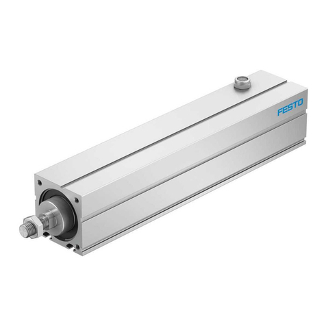
Connecting an axis to a motor in axial configuration to the driven shaft. Fulfils
degree of protection IP65.
2.2.2 Permissible Axes and Motors
NOTICE!
Overloading can cause malfunction and material damage.
The motor’s output variables must not exceed the permissible values of the com-
ponents used.
Permissible values èwww.festo.com/catalogue.
• Limit the motor’s output variables accordingly.
• Derive the axis and motor from the interface codes.
Example: EAMM-A-D32-42A
D32: Axis interface
42A: Motor interface
Example: EAMM-A-D32-42A-S1
D32: Axis interface
42A: Motor interface
Axis interface Axis1)
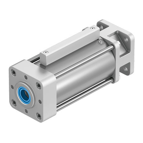
D32 ESBF-32
1) electric cylinderESBF
Tab. 1
Motor interface Motor1)
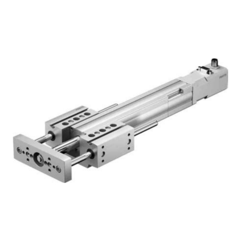
42A EMMS-ST-42, third-party motor
1) stepper motor EMM...-ST
Tab. 2
2.3 Training of Qualified Personnel
Mounting only by qualified personnel.The qualified personnel must be familiar
with the assembly of mechanical drive components.
3 Additional information
– Accessories èwww.festo.com/catalogue.
4 Scope of Delivery
1Coupling hub (2x)
2Locking screw (2x)
4Seal (1x)
5Coupling housing (1x)
7Screw (4x)
8Seal (1x)
9Motor flange (1x)
10 Screw (4x)
11 Seal (1x)
12 Screw (4x)
Fig. 1 Scope of Delivery
5 Mounting
5.1 Assembly
5.1.1 Coupling Preassembly
Fig. 2 Disconnect the coupling
1. Pull apart coupling.
2. Place the elastomer spider[A] on one of the two coupling hubs[1].
3. Loosen locking screws[2].
Fig. 3 Push on coupling hub, axis-side
• Push coupling hub[1] with the matching drilled hole onto the drive shaft[B].
Fig. 4 Align coupling hub, axis-side
8113594
EAMM-A-D...-...A/P/R-S1-7
Axial kit
8113594
2019-11d
[8113596]
Instructions| Assembly
Festo SE & Co. KG
Ruiter Straße 82
73734 Esslingen
Germany
+49 711 347-0
www.festo.com
