Flex VC12 User manual

AATTENTION!
Read all safety rules careful
ly before attempting to oper ate.
Retain for future reference.
AATTENTION!
lire attentivement lesconsignes
de securite avant d'utiliser cet
aspirateur.Conserver ce Guide
pour s'y reporter ulterieurement.
AiATENCION!
Lea cuidadosaments todas las
normasdeseguridadantesdeuti
lizar la aspiradora. Conserveeste
manual para futuras consultas.
ADANGER!
Never operate this unit when
flammable materials or vapors
are present because electrical
devices produce arcs or sparks
that can cause afire or explo-
sion.
NEVER OPERATE
UNATTENDED!
ADANGER!
Nejamais utiliser cetaspirateur
en presence de vapeurs ou de
matieres inflammables. Les
appareils electriques produisent
des arcs ou des etincelles qui
peuvent causer un incendie ou
uneexplosion.
NEJAMAIS LAISSER
FONCTIONNER CET
APPAREILSANS
SURVEILLANCE!
AiPELIGRO!
Nunca opereesta unidad ante
la presencia de materiales
inflamables ovapores, ya que
los aparatos electricos produ
cen arcos o chispas que pueden
causar un incendio o una
explosion.
iNODEJELA ASPIR
ADORA
FUNCIONANDOSIN
VIGILANCIA!
Wet/Dry Vacuum
AspirateurSec/Humide
Aspiradora para Liquidos/S61idos
VC12
Usermanual.Please review before operating vac. Guide
de Putilisateur.Alire avant d1utiliser l'aspirateur.
Manualdel usuario. Porfavor leaeste manualantes deusarla aspiradora.
Model/Modele/ModeloQL600DF
Commercial/Industrial Use
A usagecommercialet industriel
ParaUso Comercial/lndustrial
PatentsIssuedand Pending.
Brevets delivres eten instance.
Patentes registradas yen tramite.
All Rights Reserved.
Tous droitsreserves.
Todos los derechos reservados.87547-81

IMPORTANT SAFETY INSTRUCTIONS
When usinganelectricalappliance,basic precautions shouldalways be followed, including
the follow ing:READ ALL INSTRUCTIONS BEFORE USING THISAPPLIANCE.
A WARNING -TO REDUCE THE RISK OF FIRE,ELEC
.TRIC SHOCK OR INJURY:
1. Donotleaveappliancewhenpluggedin.Unplugfromoutletwhennotin useandbefore
servicing. Connect toa properly grounded outlet only. See GroundingInstructions.
2. Do notexposetorain -storeindoors.
3. Donotallowtobeusedasatoy. Closeattentionis necessarywhenusedbyornearchil dren.
4. .Useonlyasdescribedinthismanual.UseonlyManufacturer's recommended attachments.
5. Donotusewith damagedcordorplug.Ifapplianceisnotworkingasit should.hasbeen
dropped,damaged,left outdoors or dropped intowater, returnit to aservice center
6. Do Not:pull or carry bycord.usecord as ahandle ,close adooron cord or pull cord around
sharp edges or corners. Do not run applianceover cord.Keep cord away from heated
suriaces.
7. Do notunplugby pullingon cord.To unplug.graspthe plug; nottl1e cord.
8. Do nothandle plugorappliancewith wet hands.
9. Donotputanyobjectintoopenings.Donotusewitl1anyopeningsblocked;keepfreeof dust,
lint.l1air and anythingthat may reduce airflow.
1. Keephair,looseclothing,fingersandallpartsofbodyawayfromopeningsandmoving parts.
2. Donotpickupanythingthat isburningorsmoking, suchascigarettes,matchesorhot ashes.
12. Do notuse without dust bag and/orfiltersin place.
13. Turn off allcontrols before unplugging.
14. Use extra care when cleaning onstairs.
15.Do not use to pick up flammableor combustible liquids such as gasoline or use inareas
where they may bepresent.
16. Donot use yourcleaner as asprayerof flammable liquids suchasoil base paints, lacquers,
household cleaners, etc.
17. Do not vacuum toxic , carcinogenic ,combustibleor other hazardous materials such as
asbestos ,arsenic ,barium, beryllium, lead,pesticides or other healtl1endangering materi
als.Speciallydesigned unitsareavailableforthesepurposes.
18. Do notpick up soot,cement,plaster or drywall dust without cartridge filter and collection
filterbag in place.These are very fine particles that maypassthrough thefoamandaffect
tl1eperiormance of the motor or be exl1austedbackinto the air.Additional collection filter
bagsare available.
19. Do not leave the cord lying on the flooronce you have finished the cleaning job.It can
becomeatripping hazard.
20. Use specialcare when emptying heavily loadedtanks.
21. To avoidspontaneouscombustion, empty tank after each use.
22. The operationof autilityvaccan result in for eign objects beingblown into eyes,which can
resultineye damage.Alwayswear safety goggleswhenoperating vacuum.
23. STAYALERT.Watch what youare doing anduse commonsense.Donot usevacuum cleaner
when you are tired,distracted or under the influence of drugs, alcohol or medica tion
causing diminishedcontrol.
24. WARNING! DoNOT use thisvacuum cleaner to vacuum lead paint debris becausethis may
disperse fine lead particles into the air.This vacuumcleaneris not intendedfor use under
EPA Regulation 40 CFR Part745 for leadpaintmaterialcleanup.
SAVE THESE INSTRUCTIONS
A WARNING -DONOT LEAVE VACUUM UNATIENDED WHEN ITISPLUGGED IN AND/OR OPERATING.UNPLUG UNITWHEN NOT INUSE.
GROUNDINGINSTRUCTIONS
Thisappliance mustbe grounded. Ifit shouldmalfunctionorbreakdown,grounding provides a
pathof leastresistancefor electr ic current to reduce the riskof electric shock.This applianceis
equipped witl1acord havingan equipment-grounding conductor and groundin gplug .The plug
must beinserted intoan appropriateoutletthat isproperlyinstalledand groundedin
accordancewithalllocal codes andordinances.
AWARNING -IMPROPER CONNECTION OF THE
.EQUIPMENT-GROUNDING CONDUCTOR CAN RESULT IN A RISK
OFELECTRICSHOCK.CHECKWITHAQUALIFIEDELECTRICIAN OR
SERVICE PERSON IF YOU ARE IN DOUBT AS TO WHETHER THE
OUTLET IS PROPERLY GROUNDED.DO NOT MODIFY THE
PLUGPROVIDEDWITHTHEAPPLIANCE-IF ITWILL NOTFIT THE
OUTLET, HAVE APROPER OUTLET INSTALLED BY AQUALI FIED
ELECTRICIAN.
This appliance is for use on
anominal120-volt circuit.and
hasagrounded plugthat looks
like theplug illustratedin
sketch A. Atemporary adapter
that looks like the adapterillus
trated in sketches Band Cmay
beusedtoconnect thisplug to a
2-pole receptacle as shown in
sketch Bifaproperly grounded
outlet isnot available.The tem-
porary adapter should beused
only until a properly grounded outlet (sketch A) can be installed by a qualifiedelectrician.
The green colored rigid ear, lug or the like extending from theadapter mustbe connected to a
permanentgroundsuch asaproperlygroundedoutlet boxcover.Wheneverthe adapteris used,
it must be heldin place by ametal screw.
INCANADA.THE USE OF ATEMPORARY ADAPTOR IS NOT PERMITIED BY THE
CANADIAN ELECTRICAL CODE .Make sure that theapplianceis connected toanoutlethav ing
the same configuration as the plug.No adaptershouldbe usedwith thisappliance.
GROUNDINGMETHODS
AOAPTc R,
METAL
SCREW
TAB FOR ··..-,- '
GROUNDING SCREW
GROUNDING
PIN
{Al
',GROUNDED /
OUTLETBOX
{BJiCl
EXTENSION CORDS
When usingtheapplianceat a distancewhereanextensioncord becomes necessary,a 3-con
ductor groundingcord of adequate size must be used for safety,andtoprevent loss of power and
overheating.Usethe table below to determine A.W.G.wiresizerequired.To determine ampere
ratingof your vacuum,referto nameplate locatedon rearof motor cover.
Volls Tota!lengtl1ofcord in feet
120V 25 50 100 I150
lirnpcrcRating
More NotMore
Than Than AWG
0-6181616 14
{4 I12
14 12
Notrecommended
6-10 18 16
10-12 '16 16
12-16 14 12
Before usingappliance,inspectpower cordforloose orexposedwires anddamaged insulation.
Make any needed repairsor replacements before using your appliance.Use onlythree-wire
outdoorextensioncords which have three-pronggrounding-type plugs andthree-pole receptacles
which accept the extension cord'splug.When vacuuming liquids,be sure the extension cord
connection does notcome incontact with theliquid.
NOTE:STATICSHOCKSARECOMMONINDRYAREASORWHENTHERELATIVEHUMIDITYOF THEAIRIS
LOW.THISISONLY TEMPORARYANDDOESNOT AFFECTTHE USEOFTHEAPPLI ANCE.TOREDUCE
THEFREQUENCYOFSTATICSHOCKSINYOURHOME,THEBESTREMEDYIS TO ADD MOISTURE TO
THE AIR WITH ACONSOLE OR INSTALLED HUMIDIFIER.
UNPACKING
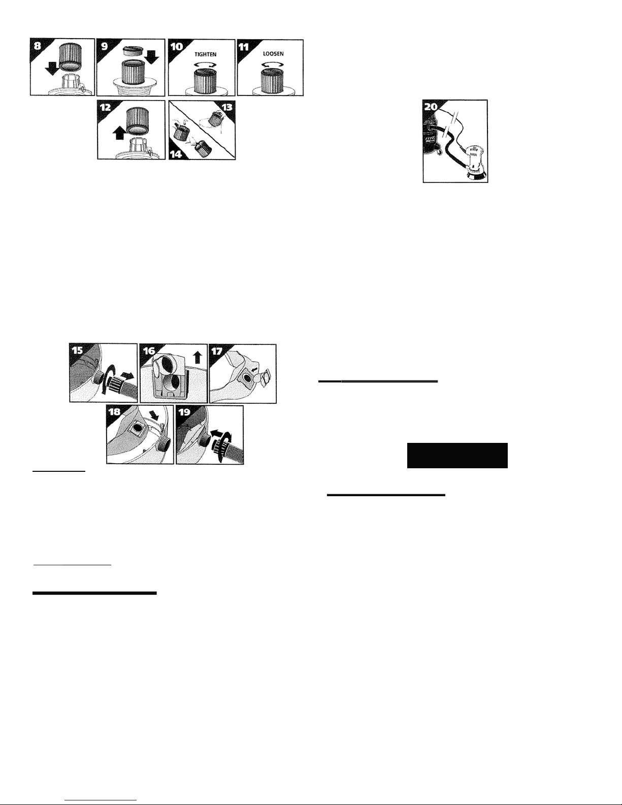
1. Removevacuum cleaner and all accessories from the carton.
2. . Important:Opentank cover bypushinglatchesor clamps outwardwith thumbs
andremove any accessories that mayhavebeenshipped in the tank.
1. Assemble dolly or caster systemfollowing instructions (See assembly).
2. Beforereplacingcover,pleaserefer to Dry Pick up or Wet Pick up operation to
ensure properfilterinstallation.
3. Replacecoverandmakesure latches or clamps aresecuredoverraisedarea of
tank cover.
2

ASSEMBLY
INSTALLING THEDOLLY
1. Remove headfromtank andplacetankupside down ona flatsurface.
2. Placewheelsonrearframe/axleassemblywith extendedhubofwheeltowardsdollyframe and
placecap nuts on axle.Securewith hammer.
3. Ifnotalreadyinstalled.insert castersocketintofrontf rameandsecurewith phillips head
screw.
4. Place groove in frontframe intolipof tank and position soframe is directly above inlet.
5. Position grooves of rear frameintolip of tank and alignso rearand front frames engage.
6. Securedollyframetotankbyplacing machinescrewsupthroughholesin dollyframe.
Ensureheadofscrewis fullyrecessedin areaprovided.Aftermachinescrew is inserted,
lightenwith flatwasher and hex nut.
7. Insert caster incastersocket andapply downward pressure untilcaster snaps into place.
8. ReturnvacuumtouprightpositionAttachcarriagehandleto tankbyinsertingboltthrough the
centerholeofhandleandtank, securewithnut provided.Attachsidehandleswith screws
provided.Besuretospreadendsofcarriagehandlewhenassemblingtoprevent damage to
tank. ITEM NUMBER &DESCRIPTION
1. Capnut
2. 8"wheel
3. Axle
4. Rearframe
5. Castersocket
6. Front frame
7. #8x1/2"lg. Screw 8.
1/4-20X 3/4" lg.
Machinescrew
9. 1/4" Flatwasher
10. 1/4-20Hex nut
11. Caster
I
ITEM NUMBER &DESCRIPTION
1. Metal tankhandle
2. Sidetank handle
3. #10 x 3/4"Screw hex head
4. Bolt1/4 -20X 1/2"
5. 1/4-20 Hex nut
- )+ - 4
GroundStrap Instruction
Staticshocksarecommonin dryareasorwhentherelativehumidity of
theair is low. Thisis onlytemporaryanddoesnotaffecttheuse of the
appliance.
Toreducethefrequencyofstaticshocksin yourhome,thebest
remedyis toaddmoisturetotheairwith aconsoleorinstalled
humidifier.
PLEASEINSTALLTHISGROUNDINGCHAINANDCLIPONTHEBOTIOMOFTHETANK
LIPBETWEENTHE BACK WHEELS.THIS SHOULD HELP REDUCETHE STATIC SHOCK
(Figure 1).
Posi-Lock Hoses
Choose correcthose foryour application.
Usel1osewith straightaccessoryhoseend(Figure2)forstandardcleaningapplications.
Use llosewit11tool adaptor (Figure 3)for usewith power tool.
Insert hose collarontothreadedtankinlet and tighten (Figure 4).
All Frictionfit wands
Insertwand endstogether and twist to forma tightfit (Figure 5).
All Frictionaccessories
Insert wand end or hose into accessory and twist to formatight fit (Figure6).
DualSurfaceSelector Nozzle
Levers control brush positionfor various types ofcleaning (Figure7).
OPERATION
f!1•E [c1=1;1
This equipment incorporates parts such as switches, motors or
the like that tend to produce arcs or sparks that can cause an
explosion. Do not pick up flammable, combustible, or hot materi
als. Do not use around explosive liquids or vapors, as electri-
cal devices produce arcs or sparks which can cause a fire or
explosion -do not use at filling stations or anywhere gasoline is
stored or dispensed.
NEVER OPERATE UNATTENDED!
IAWARNING I
ALWAYSDISCONNECTTHEPLUGFROMTHEWALLOUTLETBEFOREREMOVING THE
TANK COVER.
IACAUTION I
Keep Filters Clean
The efficiency ofthis vacuum cleaner islargelydependent onthe filter.
Aclogged filter can cause overheating and possibly damage the vacuum
cleaner.
Cleanor replace filters regularly. Donot usethe vacuum or filtersfor collecting
l1azardous or other healthendangering materials.
NOTE: Never machinewash or dry filters.
OryPick up
Cartridge Filter
Use the cartridge filter in position over the lid cage for most ofyour general dry
materialpickup. Note: Cartridge filter canalso be used for wet pick up.
ANOTICE
This filter is madeof high quality paperdesigned to stop small
particlesof dust. Thefilter can beusedfor wet or dry pick up. Adry
filter is necessaryto pick updry material.If youuseyourvac to pick
updustwhenthe filter is wet, the filter will clogquickly andbevery
difficult to clean. Thefilter maybecome saturated when picking up
largequantities ofliquid causing misting to appearin the exhaust air.
Atthis time, youshould dry or change the filter to eliminate this
occurrance. Please handle the filter carefullywhen removing it for
cleaning or when installing it. Checkthe filter fortearsor smallholes.
Evena small holecancausedust to beexhausted.Do not usea filter
with holesor tears. Replaceit immediately.
Installing &Cleaning:
1. Slidecartridgefilterdown over filtercage (Figure 8).
2. Placefilter retainer on topofcartridge filter (Figure9).
3. Holdontobaseoflidcage with one handandturn retainerclockwisetotighten (Figure 10).
4. Toremovefilterforcleaning,againholdontobaseoflidcagewith onehandandturn
retainer counterclockwise toloosen (Figure 11).
5. Slidecartridge filter offfiltercage (Figure 12).
6. Cleandry filter bytappingit oninsideof waste can (Figure 13).
7. Cleanwet filterbyrinsingfrom the inside (Figure 14).
8. Whenwet (topreventmoldand/ormildewbuild-up),thecartridgefiltershouldberemoved and
allowedtoairdry for a24-hour periodbefore beingreinstalledback onto thefiltercage.
3

DisposableFilter Bag
(Not standardwith all models)
1. Usetordrypickuponly.Useinconjunctionwit11cartridgefiltertor pickingupsoot.
cement,plaster or drywalldust.
2. Withcorddisconnectedfromreceptacle,pulllatches in anoutwardmotionandremove
tank cover.
3. Unscrew hose locking,nutand remove hose from inlet (Figure 15).
4. Removeinletdeflectorfrom deflector guide(Figure 16). NOTE:Hosemustberemoved
before inletdeflector can be takenout.
5. Wit11 theopeningof tl1einlet deflector facingtheleft orright side of the filter bag, slide filter
bag collar over deflector matching notches of bag collar to tabs on inlet deflector,bag will
onlyfit properly one way (Figure 17).
6. Slide deflectorwith collection bag attached intodeflector guide (Figure 18).
7. Reinsert hose intoinlet and tighten locking-nut(Figure 19).
8. When secured in place,expand bag and positionaround the insideoftank.
9. Replace tankcover.
NOTE:Whenremovingfilter bagfromtank, removeinletdeflectorfromfilter bagcollarand
reinstallintodeflector guide.Inlet deflector should always bein place for any type ofcleaning.
WetPick up
RemoveALLdrypickupfilters.Wetpickuprequiresonlyafoamsleeveor cartridgefilterbein
positionoverthelid cage.Donotusedry usefiltersforwet pickup. Whenpicking upseveral tanks
full of liquid,thefilter will become saturatedand mistingmay appear inthe exhaust
air.Atthistime,yousl1oulddrythefilterorchangetoadry filterto eliminatethemistingand
possibledrippingofliquidaroundthelid.Aftercompletingawet pickupjob,raisethehoseto
drainanyexcessliquid into tankbeforeshuttingoffthevac.Theinteriorofthetankshouldbe
periodically rinsedclean.
Note: Wetpick upaccessoriesshouldbewashedperiodically with soapandwater.especially
after pickingupwet, sticky liquids.
Power Tool Outlet
IAWARNING I
DO NOT PLUG ANY TOOL OR APPLIANCE RATED OVER 8 AMPS
INTO THE OUTLET ON THE VACUUM CLEANER. CHECK NAME
PLATE OF THE TOOL FOR THE AMP RATING. TO REDUCE THE
RISK OF INJURY, TOOL MUST BE TURNED OFF BEFORE PLAC
ING SWITCH IN THE AUTO POSITION.
3 Position Power Switch
Position"O" (Center) -Off
Position ''I" (UP) -Vacuum OnlyDn
Position"Auto" (Down)-Vacuumautomaticallystarts whenpowertoolpluggedintooutletis
triggered. Vacuumwill shutoffwhenpowertool is turnedoff(afterabrief delaytoclearthe
hose.)
Set-up
1. Referto theAssemblysectionin thismanualto selectthecorrecthosefor this application.
Connectvacuum hosetotool'sdust collectionport.
2. With tl1e power switch inthe"O" (off) position.plug power cordof thetool (alsoturned off)
intotheelectrical outletonthe vacuum cleaner'smotor head.
3. Withthepowerturned off,movethe vacuum's switchto the"Auto"position.
Operation
Whenevertl1epowertool is turned onthevacuumwill start.Whenthepowertool is turned off
therewill beadelayto clearthehose.andthevacuumwill stop.The timeof thedelaywill vary
with the amountof currentdrawnfrom the utility outlet (Figure20).
Utility Outlet Loadvs. Vacuum Performance
Theuniquedesignofthefeatureofthisunitwill causethevacuumperformanceto varywith the
amountofcurrent drawnfromtheutility outlet.Theelectroniccircuitautomatically adjusts the
powerofthevacuumunitto compensatefor thepowerbeingdrawnfromtheutilityoutlet This
adjustmentallows thetotalsystemcurrent drawto staywithin thesafetyregulatory agencies
maximumof12Amps.Whatevertheamountofcurrentbeingdrawnforutility work, theremainder
ofthe12 Ampsis allottedto thevacuumunitto providethemaximumallow ablevacuum
performanceduringtl1ework. Assoonastheutilityworkstops-thevacuum returnstofull power
duringthe delay periodbeforeturning off.
Automatic Shutoff
Thevacuumcleanerisequippedwith anautomaticshutoffthatoperateswl1enpickingup
liquids.Whentheliquidinthetankreachesacertainlevel,aninternalfloatwill seatitself
againstasealattheintakeofthemotor,shuttingoffsuction.Whenthishappens,themotor will
developahigl1erthannormalpitchnoiseindicatingthatyouneedto switch offthevac and
emptythe liquid.
Note:Ifaccidently tipped over,thevacuumcouldlosesuction.If thisoccurs,placevac in
uprightpositionandturnswitc hoff.Thiswill allowthefloatto return toitsnormalposition.
and you will beable to continueoperation.
IA CAUTIONI
EmptyingTank
Usespecialcarewhenemptying11eavilyloadedtanks.Liquidwaste maybeemptiedby removing
thetankcover.Toempty,stopthemotorandremovetheplug fromtlie wallrecep tacle.Remove
thetankcoveranddeposittheliquidwastecontentsin asuitabledrain. After tankis empty,
returnthecovertoits originalposition.Tocontinueuse,plug thecordinto t11ewall receptacle
and turnthe uniton.
MAINTENANCE
I AWARNING I
BE SURE TO DISCONNECT POWER SUPPLY BEFORE ATTEMPTING TO SERVICE
OR REMOVE ANY COMPONENTS.
Storage
Beforestoring thevacuumcleaner,alwaysemptyandcleanthetank.Neverallowdebristo sit in
the tankfor any extended periodoftime.Always storethe vacuumcleaner indoors.
Lubrication
No lubrication is necessary asthe motor is equipped with lifetime lubricated bearings.
Service
Donot attempttoserviceyourwet/dryvacuumcleanerbeyondthat describedinthismanual.
Refer allother servicingto aqualifiedservice center.
Thisunitincorporateselectronic circuitry. It is recommendedthat repairor parts replacement
be performed byaskilled technician.
4

PARTS LIST QL600DF
VC12
ITEM DESCRIPTION PART NO.
1Screw tr uss head % x 3h type AB1514699
2TopHandle 2410500
3Screw #8x Y2 Ph pan hd type AB1500799
4Motor cover assembly (Includes 5-13)1945078
5Receptaclecover 6195896
6Mountingplate2414800
7Screw 10-24 x1/z 0810799
8Hex Nut/r10-24 1300999
9Receptace1210027
10 Double pole rocker8232402
11 Circuitbreaker 1210028
12Foam insert cover 2412515
13 Circuit boardassembly 6195697
14 Screw 8x 31,, pan HD 1503199
15 Motor housing 2410709
16 Cord 4153400
17 Cord retainer 2411107
18 Inner housing acoustical foam 1290400
19 Upper motor gasket 2072000
20 #10-24x ·1," lg. Ground screw 1700899
21Outer housing. acousticalfoam 1290503
22 (t)Motor wfTCO 1496397
23 BallFloat 0081100
24Stripgasket2071100
25Latch 8550101
26 lidcage assembly 8988724
27 #10x % s:rew1503999
28Cartridqefilter 9034005
29 Filter retainer 3008000
30 High Efficiency Collection Bag 9067205
31Tank AssEmbly 1945077
32Inlet Deflector 7413120
33 Carriage Handle 2081101
34 Handle and Hardware package
(Includes 35-36) 9355196
35 Side Tank Handle 9355100
36 Screw #10x 31,," Hex Head1503999
37 Drain Cao 7446800
38 Cap nut 4300299
39 8"Wheel 2425010
40 Axle 2441500
41 Rearframe9392120
42 Caster socket 7540500
43 Frontframe 9392010
44 #8x W' lq Screw 1501599
45 % -20x 31," lg. machine screw0902999
46 %" Flatw2sher 0700399
47 % -20 Hex nut 1300199
48 Caster6773900
49 Ground-Strap Assembly 8600196
'i' 'i' 1
2
,:=t\I
14
'----
'i' 'i'
17 If'
15
1
2
9
0'i'
ca-
18c:::J-
21
23------o
24 C:::-
25---1?)
27 1111 1 1
28
29-·---···---
- - -26
30
1
y
33----- > -
32-- -
35--- ---:.e,"'====,,L
36
0-37
t 38
39
6
Detail
Drawing A
(t ) Motor brushes No. 1599900
*Replacement parts may differ from original equipment.
Other manuals for VC12
2
This manual suits for next models
1
Table of contents
Other Flex Vacuum Cleaner manuals

Flex
Flex VCE 45 H AC User manual

Flex
Flex VC 2 L MC Hip 18.0-EC User manual

Flex
Flex VCE 45 L AC User manual

Flex
Flex VC 25 L MC User manual

Flex
Flex S 47 User manual

Flex
Flex VCE 33 M AC User manual

Flex
Flex VC 6 L MC User manual

Flex
Flex VCE 33 L MC User manual

Flex
Flex VCE 35 L AC 110/BS-4h User manual

Flex
Flex VCE 35 L AC User manual

Flex
Flex VC 6 L MC 18.0 User manual

Flex
Flex VC 21 L MC User manual

Flex
Flex VCE 33 M AC User manual

Flex
Flex FX5221 User manual

Flex
Flex VC 6 L MC 18.0 User manual

Flex
Flex VCE 33 M AC User manual

Flex
Flex VC 25 L MC User manual

Flex
Flex VC12 User manual

Flex
Flex S 47 M User manual

Flex
Flex VCE 22 M MC User manual