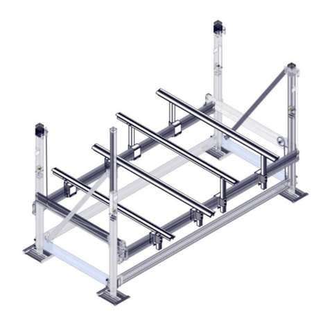
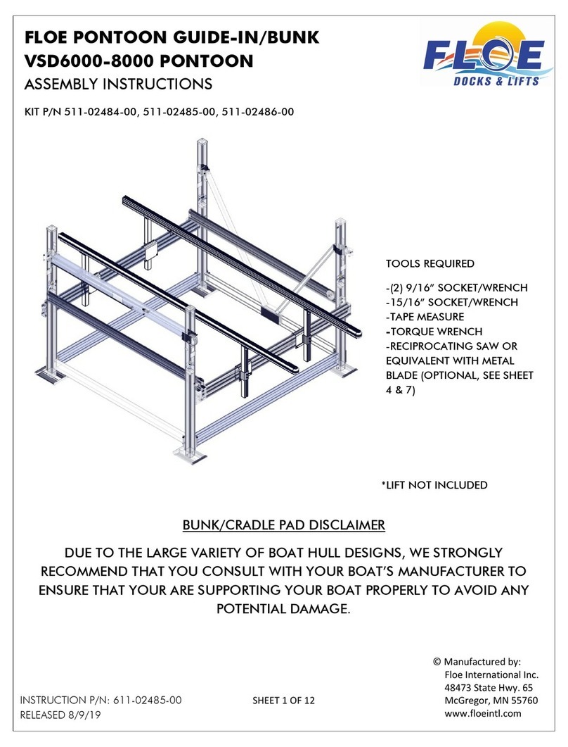
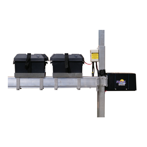
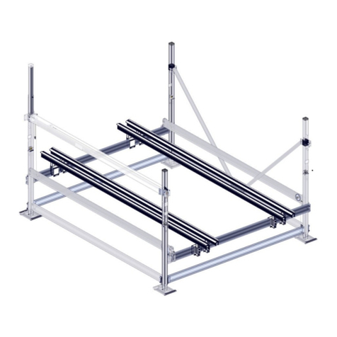
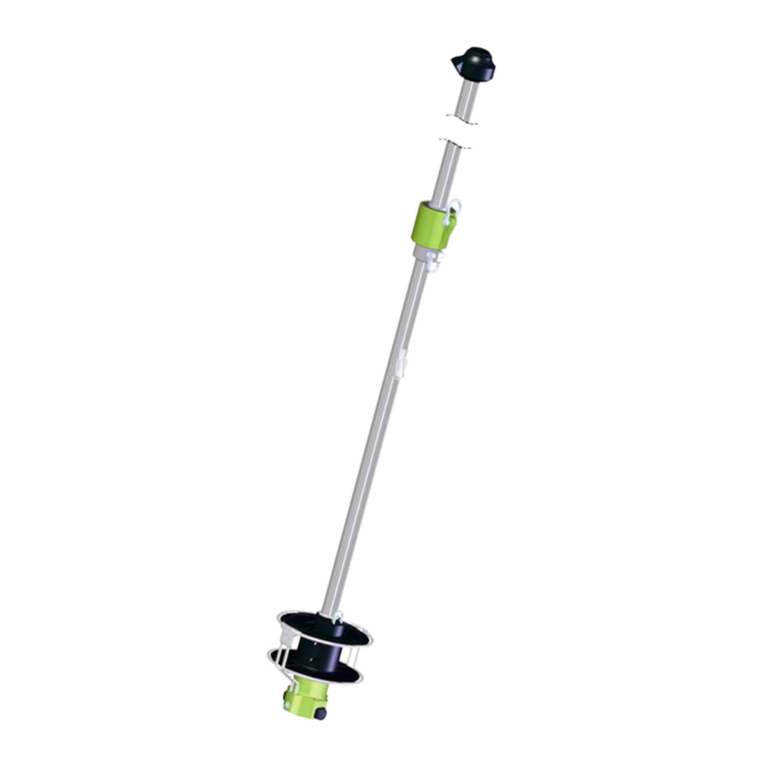
Floe VSD6500 User manual


SHEET 3 OF 12
73
1
1
1
1
1
1
2
2
3
4
4
5
5
6
6
6
6
7
7
8
9
10103
11104
12105
13
14
15
15
15
16
16
17
18
20106
21107
22108
22109
23 111 SEE SHEET 4
24
25
26
27
27
27
27
29
30
30
30
30
31
31
31
32
32
32
32
33 33
33
34
34
34
34
35
41
42
44
44
43
43
45
45
46
46
47
49
49
49
71
54
54
55
55
55
55
56
57
57
58
58
58
58
79
59
73 60
60
60
61
61
61
61
61
63 64 65
69
65
66
66
66
69
68
68
66
69
69
69
69
65
69
53
60
60 73
73
73
73
78
78
79
78
79
79
79
79
79
58
79
79 79
58 79
58 79
79
95
79
79
84
86
86
87
89
90
91
95
79
79 96
99
78
78
97
98
VSD-6500 Frame Exploded View
LIFT P/N 511-65075-01
46
45

22
77
70
39 38
40 75
88
19
7674
61
79
27
11028
62 80
51
47
79
23 111
37
48
24
83
82
81
SHEET 4 OF 12
68 35
68
42
65
87
69
86
85
72
72
91
90
89
72
93
72
93
72
95
94
78
92
56
67
52
78
IMPORTANT: VERIFY THAT THE
LIFTING CABLE IS POSITIONED
OVER THE TOP OF THE
BALL SCREW SUPPORT BOLT
VSD-6500 Frame Exploded View
LIFT P/N 511-65075-01
IMPORTANT: INSERT BOLTS
THRU HOLES IN BEARING BLOCK
101
100
50

SHEET 5 OF 12
Attach sand pads to all four corner post assemblies
using (4) 1/2" x 5" bolts and (4) 1/2" nylock nuts.
Torque to 25 ft/lbs. See Fig 1A.
Arrange corner posts as shown to the right and in
Fig. 1A thru Fig. 1E.
1/2" x 5" Bolt
1/2" Aluminum
Nylock Nut
Fig. 1B
Fig. 1D
Fig. 1E
Fig. 1A
Fig. 1A
Fig. 1B Fig. 1C Fig. 1D Fig. 1E
Right Front
Corner Post Ass'y
Right Rear
Corner Post Ass'y
Left Rear
Corner Post Ass'y Left Front
Corner Post Ass'y
Sand Pad
Sand pad 1C
Step 1

SHEET 6 OF 12 Fig. 2D
Fig. 2C
1/2 x 4" bolts, flatwashers,
& nylock nuts.
Fig. 2B
Fig. 2D
Fig. 2C
Frame beams are fastened to the corner posts
using the pre-attached lower clamps. See corner
post layout in Fig. 2A. Insert frame beam spacers
into ends of all four frame beams before assembly
as shown in Fig. 2B. For ease of assembly, lay the
108" side frame beams between the front and rear
corner posts and fasten to the corner posts using
(4) 1/2" x 4" bolts, (8) flat washers, and (4) nylock
nuts as shown in Fig. 2C&2D. Torque to 80 ft./lbs.
Attach the cable end of the tube using, (2) 3/8"
x 6" bolts and (2) nylock nuts. The ball screw
end is attached using, (1) 3/8" x 6" bolt & nylock
nut, & (1) 1/2" x 6" bolt & nylock nut.
IMPORTANT:Make sure to insert bolts thru holes
in bearing block.
Fig. 2E
1/2" x 6"
3/8" x 6" 3/8" x 6"
3/8" Nylocks
1/2" Nylock
1/2 x 4" bolts, flatwashers,
& nylock nuts.
At this time torque the bolts that
were just installed:3/8" bolts to
35 ft/lbs.-1/2" bolts to 80 ft/lbs.
Grease
Hole
3/8" x 4 1/2"
Attach the ball screw clamp to the corner post using
(2) 3/8" x 6" bolts, and (2) nylock nuts, torque to
35 ft./lbs as shown in Fig. 2E. The 109" ball screw
tube is attached using the clamps on the lifting
corner post & the ball screw clamp that was just
installed. Torque to 35 ft./lbs.
Orient the ball screw tube so the large grease
hole is on the side facing out. Pull the cable out
the other end so there are no kinks in the cable.
IMPORTANT: Verify that the lifting cable is
positioned over the top of the ball screw support
bolt before proceeding to the next step! Insert the
coupler end of the ball screw into the hole in the
corner post. Thread the cable from the other end
through the corner post slot and over the sheaves.
Place a 3/8" x 4 1/2" bolt w/ nylock in remaining
hole in lift post clamp. Torque to 35 ft./lbs.
Step 2
Ball screw
supt. bolt
IMPORTANT: THE LIFTING
CABLE MUST GO OVER
THE TOP OF THE UPPER
BOLT IN THE BALL SCREW
CORNER POST CLAMP
IMPORTANT: INSERT
BOLTS THRU HOLES
IN BEARING BLOCK.

Fig. 3A SHEET 7 OF 12
Slide the two lower V-brace clamps
together. See Fig. 3A. Locate the
lower V-brace clamps approximately
in the center of the side frame beam.
Fasten the V-braces to the lower
V-brace clamps w/ (2) 3/8" x 3 1/2"
bolts and nylock nuts. See Fig. 3B.
Attach the diagonal V-braces to the
upper V-brace clamps using (2) 3/8"
x 3 3/4" bolts and nylock nuts as
shown in Fig. 3C.
Male
V-brace
Clamp Female
V-brace
Clamp
3/8" x 3 1/2 "
Bolts
3/8" Nylock Nuts
Fig. 3B
Fig. 3B
V-Braces
Upper Clamp
Upper Clamp
At this time you may have to slide the
lower V-brace clamp horizontally
along the side frame beam to be
able to align the upper V-brace with
the holes in the corner posts. Once
aligned attach the upper V-braces
clamps to the corner posts using (2)
3/8" x 6" bolts and nylock nuts. Lower
Clamp
Fig. 3C
3/8" x 6"
Bolt
3/8"Nylock Nut
3/8" x 3 3/4" Bolt
Fig. 3C
Step 3

SHEET 8 OF 12
At this time you need to square the frame.
Using a framing square as shown in Fig.
4A & 4B gradually tighten each bolt a little
at a time, and alternate checking for
squareness at all corner posts. Torque all
clamp bolts to 80 ft/lbs.
Attach the 118" rear frame beam to the
assemblied side frames using (4) 1/2" x
4" bolts, (8) flat washers, and (4) nylock
nuts. See Fig. 4A. The front frame beam
is attached the same as the rear but use
(2) 1/2" x 4" bolts in the top holes only.
See Fig. 4B.
The bolts in the bottom holes will be
installed in a later step.
1/2" x 4" Bolts
w/ Nylock Nuts
Fig. 4B
Fig. 4A
1/2" x 4" Bolts
w/ Nylock Nuts
Fig. 4B
Fig. 4A
1/2" x 4" Bolts
w/ Flatwashers,
& Nylock Nuts
1/2" x 4" Bolt
w/ Flatwashers,
& Nylock Nut
Framing
Square
Framing
Square
Step 4

SHEET 9 OF 12
Now place the front cradle beam so the end
of the beam at the lifting post has the cable
on the top of the sheave. See front cable
orientation to the right.
Slide (1) cradle clamp over each end of the front
and rear cradle beams. Place (1) cradle U-clamp
over end of each cradle so the bolt holes are
aligned in the U-clamp and the side cradle beam.
Attach the the U-clamps to the side cradles using
(8) 3/8 x 1-1/4" bolts and (8) nylock nuts. Torque
to 35 ft/lbs. Attach the rear cradle beam by sliding
the cradle clamps over the cradle U-clamps. Slide
a cradle clamp over each end of the rear cradle
beam and U-clamp. See Fig. 5C and 5D.
Be certain the clamp the cradle clamps snug
against the cradle u-clamp before tightening the
1/2" x 2" bolts. Also at this time confirm the 1/4"
gap between the side cradle and corner post as
shown in Fig. 5A. Torque bolts to 80 ft/lbs.
Fig. 5C
Fig. 5D
Place the left & right cradle beams on top of
the frame beams with the top cable holes to
the rear. Special attention should be taken
to insure that the cable ends are in the right
location and a 1/4" spacing is maintained
between the UHMW wear strip and the
corner post. See Fig. 5A.
At this time attach the lifting cable clevis to
the cradle lift clamp using a 3/4-16 x 2" bolt
(fine thread). Make sure the bolt is seated in
the slot of the clamp when tightening the
cable clevis. Do not tighten the clevis
completely at this point. Install a 1/2" x 2"
bolt thru the other hole in lifting clamp with a
nylock nut in the slot on the inside of the
clamp. See Fig. 5B.
Install (7) 1/2" x 2" bolts thru the hole in the
(7) cradle clamps with a nylock nut in the slot
on the inside of the clamp.
Fig. 5A
Fig. 5B
Fig. 5C Fig. 5D
Front Cradle
Cable Orientation
Approx. 1/4"
Corner Post
Side Cradle Beam
Cradle Guide
Cradle
U-Clamp
Cradle Clamp
Cradle Lift
Clamp
Cradle Clamp
Lifting
Cable
Clevis
Cradle
Lift Clamp
Step 5 Cradle U-Clamp
with bolt holes
towards the inside
of the lift (both ends
and both sides)

Fig. 6A SHEET 10 OF 12
Attach the other end of the cable by lifting the opposite
side of the front cradle and fastening with a 1/2" x 2 1/4"
bolt and nylock nut as shown in Fig. 6B. Torque to 80
ft/lbs.
Fig. 6D
Fasten the side cables to the lower frame clamps using
1/2" x 5" bolts, flatwashers, and nylock nuts as shown in
Fig. 6C. Check front corner posts for square. Torque to
80 ft/lbs.
Fig. 6B
The ball screw side cable is attached to the upper clamp
using a 1/2" x 2 1/4" bolt and nylock nut. See Fig. 6D.
The other side cable is attached to the upper clamp using
a 1/2" x 2 1/4" bolt and nylock nut as shown in Fig. 6E.
Torque both bolts to 80 ft/lbs.
Locate the cable holder and 4" sheave on the hardware
card. Wrap the cable around sheave and attach to the
clamp with a 1/2" x 2 1/2" bolt and nylock nut. Cable
holder is placed at approximately 120 degrees from
vertical clockwise (or at a 4:00 position) as shown in Fig.
6A. Now attach the cable end to the lower clamp with a
1/2" x 2 1/2" bolt and nylock nut as shown in Fig. 6A.
Torque both bolts to 80 ft/lbs.
Fig. 6C
Fig. 6A
Fig. 6E
Fig. 6B
Fig. 6D
Fig. 6E
1/2 x 2 1/4" Bolt
w/ Nylock Nut
1/2 x 2 1/4" Bolt
w/ Nylock Nut
Cable
Holder 1/2" x 2 1/2" Bolt
w/ Nylock Nut
1/2 x 5" Bolt, Flatwashers,
& w/ Nylock Nut 1/2 x 2 1/4" Bolt
w/ Nylock Nut
Fig. 6C
1/2 x 5" Bolt, Flatwashers,
& w/ Nylock Nut
Step 6


SHEET 12 OF 12
VSD Pre-installation Check List
1. Raise the lift up to confirm operation of upper limit switch. Approach the
upper limit switch cautiously by pressing the UP button in short bursts as you
near the top of the lift travel. A properly working limit switch will stop the lift
before the ball screw reaches its limit of travel. If the limit switch does not stop
the lift and the ball nut reaches the end of the ball screw you will be able to see
the drive unit twisting slightly, indicating that the motor is trying to run. Also,
you probably would have heard the ball nut hitting the metal stop at the end of
the screw. The brake will still click when stopped at the limits.
2. Lower the lift down to confirm operation of lower limit switch. Again, as you
approach the bottom of the lift travel press the DOWN button in short bursts.
The lift should stop with a small amount of slack in the lifting cable after the
cable contacts the lift frame. If the limit switch does not stop the lift and the ball
nut reaches the end of the ball screw you will be able to see the drive unit
twisting slightly indicating that the motor is trying to run. Also, you probably
would have heard the ball nut hitting the metal stop at the end of the screw.
Prior to installing your lift please follow this check list to
confirm proper operation.
If either limit switch does not stop the lift correctly, contact
FLOE customer service and do not use the lift until the
problem is corrected.
3. Listen for unusual noises during lift operation. Squeaking may indicate that
the lift may not have been greased. Both the thrust bearing and the ball nut
MUST be greased before using the lift. Please see owners' manual for details.
4. If you have a wireless remote it would be good idea to test it at this time.
There is no need to go all the way to the limit switches since those were tested
above. Also check the inside (amber) light and the mast light if you have one.
The lights come on when their buttons are pressed and go off with a second
press or after about 7 minutes of no light button activity.
2. Connect the 32" white battery interconnect wire to
the negative post of the first battery and the positive
post of the other battery.
See diagram below. Place the covers on the battery
boxes and strap it through the slots on the battery
tray.
Battery Interconnect Wire (32" White)
Black Wire
To Drive
Train
1. Connect the red wire from the ASC to the positive
post of one battery. Connect the black wire from the
ASC to the negative post of the other battery.
Red Wire
VSD-6500 Boat Lift (DC ONLY)
24 Volt Battery Connection Diagram
The drive train can now be connected to the power
source. It is very important that this connection be
made in accordance with State and Local Regulations.
SEE WARNING:
Step 8 (AC ONLY)
Other manuals for VSD6500
1
Other Floe Boating Equipment manuals

Floe
Floe FULL LENGTH BUNKS User manual

Floe
Floe 510-20000-00 User manual

Floe
Floe 510-27200-00 Quick start guide

Floe
Floe 510-89304-00 User manual

Floe
Floe VSD 6000 User manual

Floe
Floe V2602 LENGTH BUNKS User manual

Floe
Floe V1600 PWC User manual
Floe
Floe V-2000 User manual
Floe
Floe V1600 PWC User manual

Floe
Floe VSD 3800 User manual

Floe
Floe VSD 6000 User manual
Floe
Floe V-2000 User manual

Floe
Floe 510-27500-00 Quick start guide

Floe
Floe 510-27100-00 Quick start guide
Floe
Floe 510-17700-00 User manual

Floe
Floe 510-27400-00 Quick start guide

Floe
Floe VSD 5000 User manual

Floe
Floe INSTA-FLOAT Product manual

Floe
Floe 510-27300-00 Quick start guide
Floe
Floe PONTOON CRADLE PADS User manual