Fluval FX UVC User manual

EXTENDED WARRANTY WITH ONLINE REGISTRATION
GARANTIE PROLONGÉE AVEC INSCRIPTION EN LIGNE
GARANTIEVERLÄNGERUNG MIT ONLINE-REGISTRIERUNG
GARANTÍA EXTENDIDA AL REGISTRARTE ONLINE
GARANTIA ALARGADA COM REGISTO ONLINE
FREE • GRATUIT • FREI • GRATIS • GRÁTIS
YEARS
ANS
JAHRE
AÑOS
ANOS
2
3
•
3
J
A
H
R
E
G
A
R
A
N
T
I
E
•
G
A
R
A
N
T
I
E
D
E
3
A
N
S
•
3
A
Ñ
O
S
D
E
G
A
R
A
N
T
Í
A
•
3
A
N
O
S
D
E
G
A
R
A
N
T
I
A
•
3
Y
E
A
R
W
A
R
R
A
N
T
Y
+
INSTALLATION ON
FLUVAL FX2/FX4/FX6 FILTER COVER PAGE 2
INSTALLATION ON CABINET WALL WITH
FLUVAL FX2/FX4/FX6 FILTER PAGE 3
INSTALLATION ON CABINET WALL WITH
CANISTER FILTERS USING 5/8" / 16 mm HOSING PAGE 5
CL
UVC IN-LINE
FX
CLARIFIER
VC
IN-LINE

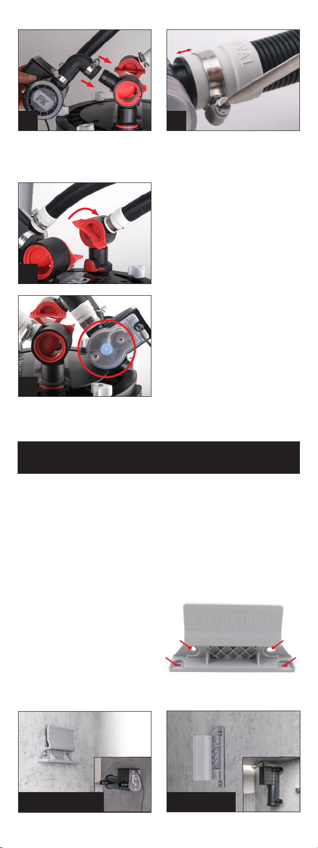
ADDING THE UVC UNIT
8. Slidemetalclampoverendoflter
output hosing (approx. 0.25" / 1 cm
from end) and attach to UVC connector
nearest to the power cord. Secure
clamp by tightening it with screwdriver.
9. Attach another metal clamp to UVC
rubber elbow adapter (approx. 0.25"
/ 1 cm from end).
ENGLISH
WHAT’S INCLUDED
UVC unit & bulb
Power supply
Bulb cover gasket
PREPARING YOUR FILTER
1. TurnlterINandOUTvalvestotheclosed(horizontal)position.
2. Unpluglterfromelectricalpowersupply.
3. Prior to UVC installation, output hosing must be emptied of water.
Todothis,removeOUTAquaStopvalvefromlter.
4. Removeoppositeendofoutputhosingfromaquariumanddrainwaterintosink
orbasin.OpenAquaStopvalvetoemptywaterfromhose.
5. DisconnectoutputhosingfromAquaStopvalvebylooseningthemetalclamp.
6. ReinstallOUTAquaStopvalvewhilepressingrmlyuntilitclicksintoplace.
7. Placetheotherendoftheoutputhosingbackintotheaquarium.
9
INSTALLATION ON
FLUVAL FX2/FX4/FX6 FILTER COVER
Metal clamps
Rubber elbow adapter
Wall mounting bracket and screws Adapters for lters with
5/8”/ 16 mm diameter hosing
8
10. Connect long end of rubber elbow
adapter to UVC unit. Secure clamp by
tightening it with screwdriver.
11. Attach another metal clamp onto
rubber elbow adapter (approx. 0.25"
/ 1 cm from end).
10 11
Replacement bulb #A19990 (sold separately)
2
0.25" / 1 cm
BB
AA
12.Attachrubberelbowadaptertolter
output valve and secure clamp by
tightening it with screwdriver.
13.Doublecheckallmetalclampsare
positioned approx. 0.25"/ 1 cm from
ends and are tightly secured with a
screwdriver to ensure watertight seal.
12
14
16
13
14.OpenlterINandOUTvalves
and wait 15 minutes to ensure
connections are watertight.
15.PluginFXltertoelectricaloutlet.
The electronic automatic priming
sequencewillbegin.
16.Ensurewaterisowingoutfromlter.
Oncecompleted,connectpower
supply to UVC unit and plug into
electrical outlet. A light indicator
(visible through the semi-transparent
lamp cover) will show that the UVC
unit is operating.
INSTALLATION ON CABINET WALL
WITH FLUVAL FX2/FX4/FX6 FILTER
IMPORTANT:
•Thisinstallationoptionrequiresone1"/25mmFXhoseforcabinetmount
(soldseparately–#A20233)orequivalent1"/25mminnerdiametervinylhose
(soldseparately).
•Self-tappingscrewssuppliedwithUVCunitaresuitableforwoodencabinet
wallswithaminimumthicknessof0.6"/15mm.Installationisnot
recommendedonmovingelements(i.e.cabinetdoors).
•UVCmustbeconnectedtolteroutputhosingonly.NeverinstallUVC
tolterintakehosing.
•EnsureUVCandhosingarealwayspositionedaboveFXltercover.
1. ToprepareFXlterforUVCinstallation,referto
the Preparing Your Filter section (steps 1-7).
2. Select desired UVC location on cabinet wall.
3. Usingascrewdriver,axmountingbracket
to cabinet wall using screw holes (A) for
horizontalpositioning,orholes(B)for
vertical positioning.
IMPORTANT:Ifinstallinghorizontally,ensuremountingbracketisplacedsothat
thescrewholesappearbelowtheFluvallogo.
3 VERTICAL3 HORIZONTAL
3

0.25" / 1 cm
4
8
5
7
9
11
4. Slidemetalclampoverendoflter
output hosing (approx. 0.25" / 1 cm
from end) and attach to UVC connector
(eithersideastheUVCworksin
both directions).
5. SlideUVCunitintomountingbracket
untilitclicksintoplace.
6. Slide metal clamp over one end of
1" / 25 mm FX hose for cabinet mount
(sold separately – # A20233) or
equivalent1"/25mminnerdiameter
vinyl hose (sold separately). Ensure
clamp is positioned approx. 0.25"
/ 1 cm from end.
7. Slide metal clamp over other end of
1" / 25 mm connection hose (approx.
0.25" / 1 cm from end) and attach
tolterOUTvalve.IMPORTANT:
For optimal performance, ensure all
hosing follows a straight path with
no loops and very little slack.
8. Doublecheckallmetalclampsare
positioned approx. 0.25"/ 1 cm from
ends and are tightly secured with a
screwdriver to ensure watertight seal.
9. OpenlterINandOUTvalvesandwait
15 minutes to ensure connections
are watertight.
10.PluginFXlterintoelectricaloutlet.
The electronic automatic priming
sequencewillbegin.
11.Ensurewaterisowingoutfrom
lter.Oncecompleted,connectpower
supply to UVC unit and plug into
electrical outlet. A light indicator
(visible through the semi-transparent
lamp cover) will show that the UVC
unit is operating.
6
4

BB
AA
3. Slide metal clamps over each of
the two 1" / 25 mm to 5/8" / 16 mm
hosing adapters (approx. 0.25" / 1 cm
from end).
4. Installhosingadaptersoneach
UVC connector.
INSTALLATION ON CABINET WALL WITH
CANISTERFILTERSUSING5/8" / 16 mm HOSING
IMPORTANT:
•Thisinstallationoptionrequiresone5/8"/16mminnerdiametervinylhose
(soldseparately).
•Self-tappingscrewssuppliedwithUVCunitaresuitableforwoodencabinet
wallswithaminimumthicknessof0.6"/15mm.Installationisnot
recommendedonmovingelements(i.e.cabinetdoors).
•UVCmustbeconnectedtolteroutputhosingonly.NeverinstallUVCto
lterintakehosing.
•EnsureUVCandhosingarealwayspositionedaboveltercover.
PREPARING YOUR FILTER
1. Iflterisequippedwithvalves,ensuretheyaresettotheclosedposition.
2. Unpluglterfromelectricalpowersupply.
3. PriortoUVCinstallation,refertoyourltermanualforhosedisassembly
procedure.Outputhosemustbeemptiedofanywaterbeforestartingthe
UVC connection process.
4. Disconnectoutputhosefromlter,ensuringotherendofhoseremainsinaquarium.
ADDING THE UVC UNIT
1. Select desired UVC location on cabinet wall.
2. Usingascrewdriver,axmountingbracket
to cabinet wall using screw holes (A) for
horizontalpositioning,orholes(B)for
vertical positioning.
IMPORTANT: If installing horizontally, ensure mounting bracket is placed so
that the screw holes appear below the Fluval logo.
2 HORIZONTAL 2 VERTICAL
34
56
5. Slidemetalclampoverendoflter
output hosing (approx. 0.25" / 1 cm
from end) and insert into hose
adapter (either side as the UVC
worksinbothdirections).
6. SlideUVCunitintomountingbracket
untilitclicksintoplace.
5

0.25" / 1 cm
910
7. Slide metal clamp over one end of
5/8" / 16 mm vinyl hosing (sold
separately). Ensure clamp is positioned
approx. 0.25" / 1 cm from end and
attach to UVC connector.
8. Attach other end of connection hose
tolteroutputvalve.IMPORTANT:
For optimal performance, ensure all
hosing follows a straight path with
no loops and very little slack.
9. Doublecheckallmetalclampsare
positioned approx. 0.25" / 1 cm from
ends and are tightly secured with a
screwdriver to ensure watertight seal.
10.Openlterinputandoutputvalves
(ifequipped)andwait15minutesto
ensure connections are watertight.
11.Pluginltertoelectricaloutlet.
12.Ensurewaterisowingoutfrom
lter.Oncecompleted,connectpower
supply to UVC unit and plug into
electrical outlet. A light indicator
(visible through the semi-transparent
lamp cover) will show that the UVC
unit is operating. 12
78
Ver.: 35/23-INT 6
Other manuals for FX UVC
1
Other Fluval Aquarium manuals

Fluval
Fluval PF2 User manual

Fluval
Fluval 10943 User manual

Fluval
Fluval Shaker 168 User manual

Fluval
Fluval FLEX User manual

Fluval
Fluval SEA EVO Troubleshooting guide

Fluval
Fluval FLEX User manual

Fluval
Fluval T Series User manual

Fluval
Fluval accent User manual

Fluval
Fluval FLEX User manual

Fluval
Fluval AquaVAC+ User manual


Popular Aquarium manuals by other brands


TMC
TMC aquaGro CO2 Compact Diffusers manual

Sicce
Sicce Nova quick start guide

Aquadistri
Aquadistri Superfish Panorama 20 Warranty and manual

D-D The Aquarium Solution
D-D The Aquarium Solution P1 PRO quick start guide

Hobby
Hobby Artemix Instructions for use

Aqua Design
Aqua Design EcoCube quick start guide