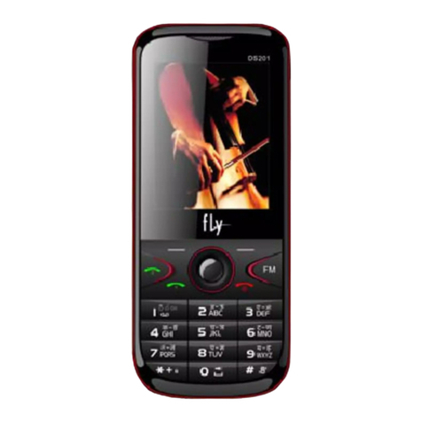
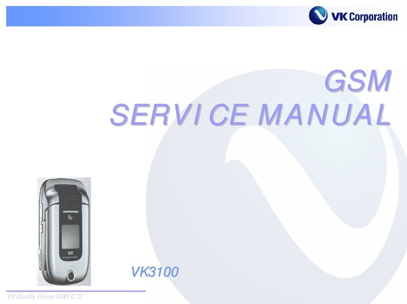
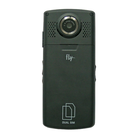
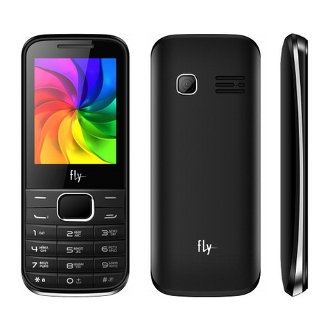
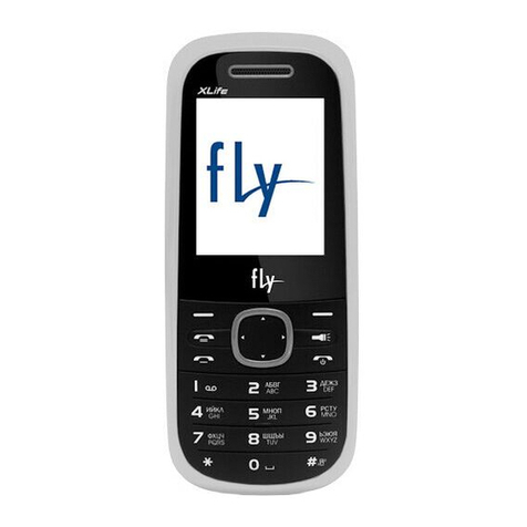
FLY DS210 User manual

confidential
DS210 Service Manual
Series No. Modification time Version No. Modified by Cause of modification Remark
1 2009/9/11 V1.0 Creation
CONTENTS

confidential
1 INTRODUCTION OF DS210 ......................................................................................................................................................................................................3
1.1 ID .......................................................................................................................................................................................................................................3
1.2 MAIN TECHNICAL SPECIFICATION .....................................................................................................................................................................................4
1.3 RF CHARACTERISTICS ........................................................................................................................................................................................................4
2PCBA OVERVIEW .......................................................................................................................................................................................................................4
3EXPLANATION OF SCHEMATIC.............................................................................................................................................................................................8
3.1 SYSTEM FUNCTIONAL DIAGRAM ...........................................................................................................................................................................................8
3.2 PRINCIPLE OF RF CIRCUIT...............................................................................................................................................................................................8
3.2.1 Main function of RF .......................................................................................................................................................................................8
3.2.2 Receiver..................................................................................................................................................................................................................9
3.2.3 Transmitter.........................................................................................................................................................................................................10
3.2.4 Frequency Synthesizer.................................................................................................................................................................................10
3.2.5 Digital Calibration Loop .........................................................................................................................................................................11
3.2.6 Fast Acquisition System............................................................................................................................................................................11
3.2.7 Voltage Control Crystal Oscillator .................................................................................................................................................11
3.2.8 Regulator .............................................................................................................................................................................................................11
3.3 PRINCIPLE OF BASEBAND CIRCUIT ..................................................................................................................................................................................12
3.3.1 Baseband chip—MT6325 ...................................................................................................................................................................................12
3.3.2 Explanation of power management unit in MT6235.....................................................................................................................12
3.3.2.1 10 channel power supply......................................................................................................................................................................13
3.3.2.2 Power on circuit ......................................................................................................................................................................................13
3.3.2.3 Charge Circuit ...........................................................................................................................................................................................14
3.3.3 SIM interface....................................................................................................................................................................................................15
3.3.4 Principle of audio frequency circuit.............................................................................................................................................15
3.3.5 LCD circuit.........................................................................................................................................................................................................16
3.3.6 Camera circuit .................................................................................................................................................................................................17
3.3.7 Bluetooth circuit ..........................................................................................................................................................................................17
3.3.8 T-flash card circuit ...................................................................................................................................................................................18
3.3.9 System interface.............................................................................................................................................................................................18
3.3.10 FM circuit........................................................................................................................................................................................................19
3.3.11 Key interface ................................................................................................................................................................................................20
4MAIN SPARE PARTS INTRODUCTION...............................................................................................................................................................................20
5FAILURE ANALYSIS..............................................................................................................................................................................................................21
5.1 LEVEL 1PRIMARY REPAIR ..............................................................................................................................................................................................21
5.1.1 Upgrade software.............................................................................................................................................................................................21
5.1.1.1 Install USB cable driver ...................................................................................................................................................................21
5.1.1.2 Upgrade software ......................................................................................................................................................................................21
5.1.1.3 Upgrade fail halfway.............................................................................................................................................................................24
5.1.2 Replace packages.............................................................................................................................................................................................25
5.1.3 The guidance for user to use some functions............................................................................................................................25
5.2 LEVEL 2INTERMEDIATE REPAIR .....................................................................................................................................................................................25
5.2.1 Cover Broken ......................................................................................................................................................................................................26
5.2.2 Replace Keypad (Structure Parts) ......................................................................................................................................................26
5.2.3 LCD Broken ...........................................................................................................................................................................................................26
5.2.4 Microphone Broken ..........................................................................................................................................................................................26
5.2.5 Receiver Broken ...............................................................................................................................................................................................26
5.2.6 Speaker Broken .................................................................................................................................................................................................26
5.2.7 Camera Broken....................................................................................................................................................................................................26
5.2.8 Receiver FPC Broken .....................................................................................................................................................................................26
5.2.9 Slide FPC Broken.............................................................................................................................................................................................26
5.2.10 LCD PCB Broken..............................................................................................................................................................................................27
5.2.11 Mainboard PCB Broken................................................................................................................................................................................27
5.3 LEVEL 3SENIOR REPAIR ................................................................................................................................................................................................27
5.3.1 Power on and initial problem................................................................................................................................................................28
5.3.2 Upgrade Problem ...............................................................................................................................................................................................29
5.3.3 Power charge problem: Charger .............................................................................................................................................................30
5.3.4 Power Charge Problem: USB .......................................................................................................................................................................31
5.3.5 RF Signal Weakness Problem (Have no signal even)................................................................................................................32
5.3.6 LCD Display Problem .....................................................................................................................................................................................33
5.3.7 LCD Backlight Problem.................................................................................................................................................................................34
5.3.8 Camera Problem .................................................................................................................................................................................................35
5.3.9 SIM I Card Problem(Phone can’t access SIM card) ..................................................................................................................36
5.3.10 T-card Problem(Phone can’t access T-flash card)...............................................................................................................37
5.3.11 Receiver Problem(Unable to hear any voice from each other during the call)..............................................38
5.3.12 Speaker Problem(Unable to hear any voice when playing MP3) ....................................................................................39
5.3.13 Microphone Problem: Internal(Microphone doesn’t work) ................................................................................................40
5.3.14 Microphone Problem: External(Earphone MIC doesn’t work)............................................................................................41
5.3.15 Earphone Problem(Unable to detect earphone insert)........................................................................................................42

confidential
5.3.16 Earphone Problem(Earhook function to stop or receive a call ) .............................................................................43
5.3.17 Earphone Problem (Unable to hear sound by earphone) .....................................................................................................44
5.3.18 Mass Storage Problem (Computer can’t detect phone’s U disk function) ............................................................45
5.3.19 Vibrator Problem .........................................................................................................................................................................................46
5.3.20 Bluetooth Problem.......................................................................................................................................................................................47
5.3.21 FM Radio Problem .........................................................................................................................................................................................48
5.3.22 Keypad Problem..............................................................................................................................................................................................49
5.3.23 Keypad Backlight Problem......................................................................................................................................................................50
5.3.24 Slide Problem(Unable to detect slide event) ........................................................................................................................51
5.3.25 SIM II Card Problem(Phone can’t access SIM card) ............................................................................................................52
5.4 LEVEL 4BOARD-LEVEL MAINTENANCE.............................................................................................................................................................................53
6DISASSEMBLY STEPS............................................................................................................................................................................................................53
Summery
In order to support technicians to be familiar with DS210 handset, please master the method of servicing.
There are many descriptions of circuit and maintaining examples. Hope it could give you some help. Service will
be divided into four levels to explain.
Level 1:Primary repair point, don’t need to disassemble the phone
Level 2:Intermediate repair point, disassemble the phone to simply replace some parts
Level 3:Senior repair point,repair PCB boards.
Level 4: Board-level maintenance, please return defective PCB boards to factory for repair.
Based on after-sales problems, we will gradually update the content of this document.
1 Introduction of DS210
1.1 ID
DS210 is a real dual-SIM and dual-online phone. It’s developed and designed based on the MTK platform. Besides
the basic call function, DS210 provides you with a collection of practical functions, including 262k colors
screen, 2.0M pixel camera, Bluetooth, FM, File manager(T-Flash card supported), recorder, MP3, MP4 player. It
also supports Java, MMS and incremental service which facilitate your work and entertainment.
The functional system is composed of radio frequency (RF) (MT6139 + SKY77518) and Baseband (BB) (MT6235).RF

confidential
includes antenna interface, FEM, PA and transceiver (power supply belongs to BB). BB includes Baseband processor
MT6235 (integrate PMU), NAND + SDRAM, LCM, CMOS Sensor, Bluetooth, FM and keyboard.
The MT6139, which is the core IC in RF, adopts direct-conversion architecture with automatic, and supports
EGSM/DCS and 26MHz VCXO reference, with a fully-integrated LC-tank VCO and integrated regulator.
MT6235, the GSM processor, is the core part in the whole BB and in the whole system. It controls speech signal
processing and normal operation of each part in the whole mainboard. It is based on the 32-bit ARM926EJ-STM RISC
processor. MT6235 is an enhanced GSM processor, in which there are channel coder and decoder subsystem that
is integrated with the channel coder & decoder, interweave & de-interweave, encryption & decryption. MT6235’s
audio features provide a rich solution for multi-media application, it supports AMR codec to adaptively optimize
speech and audio quality. Moreover, HE-AAC codec is implemented to deliver CD-quality audio at low bit rates.
MI6235 integrate a Power Manager Module, it is a highly-integrated and extremely powerful single-chip solution.
1.2 Main Technical Specification
zMain chips: MT6235, MT6139, SKY77518, MT6601, AR1000
zBand:Dual-band phone for EGSM900/1800MHz
zCamera:Integrated UXGA camera 2.0 Mega-pixels
zDisplay:Active matrix color display with 262k colors, resolution 240*320 pixels
zSIM:Dual GSM SIM cards
zBluetooth
zFM Radio
zMicro SD card
zJava
zBattery:900mAh Li-Ion battery pack
1.3 RF Characteristics
z900MHz:890~915MHz(Transmitter)935~960MHz(Receiver)
z1800MHz:1710~1785MHz(Transmitter)1805~1880MHz(Receiver)
zCarrier Frequency Spacing:200KHz
zFrequency Error:≤1×10⁻⁷
zPeak Phase Error:≤20°
zRMS Phase Error:≤5°
zMax Output Power:900MHz≤2W(33dBm)1800MHz≤1W(30dBm)
zNominal Bit Error Rate:Static channel BER≤1×10⁻⁴,EQ50 channel BER≤3%
zReference Sensitivity Level:-102dBm(900MHz),-100dBm(1800MHz)
2 PCBA Overview
zMainboard PCB Top Side

confidential
U302(MultiChipMemory)
Relevantfailures:
Unableto
p
oweron
/
Unabletou
pg
rade
Displaywhitescreen/Displayflower
screen
Relevantfailures:
VS901~VS906(LCDsignalEMIchips)
UnabletoopenBluetooth
function/Bluetoothfailto
search,link,orcall.
U801(MT6601BluetoothIC)
Relevantfailures:
U802(32MHzBluetoothCrystal)
Relevantfailures:
UnabletoopenBluetoothfunction
Relevantfailures:
Unabletodetectslideevent
U901(Hallsensor)
Unabletopoweron/Unabletoupgrade
/RFmoduleworkabnormal/LCDdisplay
problem/Cameraproblem/Unableto
chargeetc
Relevantfailures:
U6235(MT6235BasebandandPower
ManagementIC)
Unabletopoweron/Unableto
upgrade/Basebandwork
abnormal/RFModulework
abnormal
Relevantfailures:
U105(26MHzCrystal)
NoRFsignal/RFsignalweakness/
Calldropeasily/Systemclock
abnormal/Unabletopoweron,etc.
Relevantfailures:
U100(MT6139RFTransceiver)
NoRFsignal/RFsignalpoor/Call
dropeasily
Relevantfailures:
U101(SKY77518,RFDiplexerand
Poweramplifier)
Relevantfailures:
Microphonehasnosound/LCD
backlightabnormal/LCDdisplay
abnormal/Receiverhasnosound/
FunctionalkeyPCBabnormal/
Functionalkeybacklightabnormal/
Failtopoweron
CN901(51PinConnector)
zMainboard PCB Bottom Side

confidential
Displayflowerscreenwhen
previewphotos
S503(Camerasidekey)
Camerashortcutkeyisinvalid
RelevantFailures:
CON406(Cameraconnector)
RelevantFailures:
UnabletoopenCamerafunction/
UnabletodetectTcardinsert/T
cardreadorwriteabnormal
RelevantFailures:
CON602(T‐flashcardconnector)
BT201(Backupbattery)
RelevantFailures:
Unabletokeepsystemtimewhen
poweroff
U601(FMchip)
RelevantFailures:
UnabletosearchFMchannel
orFMsignalispoor.
UnabletodetectSIM1/SIM1read
orwriteabnormal
RelevantFailures:
CON601(SIM1cardconnector)
S501~S502(Volumesidekey)
RelevantFailures:
Unabletovolumeuporvolume
down
UnabletodetectSIM2/SIM2read
orwriteabnormal
RelevantFailures:
CON701(SIM2cardconnector)
CON402(systemconnector)
RelevantFailures:
Failtoupgrade/failtocharge/fail
tohearsoundbyearphone/FMRF
signalpoor
Batterycontactpoorly/failto
poweron/Unabletocharge
RelevantFailures:
CN403(Batteryconnector)
NoRFsignal/RFsignalweakness/
Calldropeasily
RelevantFailures:
CN101(RFConnector)
NoRFsignal/RFsignalweakness/
Calldropeasily
RelevantFailures:
AN101(RFAntennacontactpads)
BOTTOM SIDE
Nospeakersignal
RelevantFailures:
JP702(Speakercontactpads)
Bluetoothsignalweakness/
Difficulttosearchorlinktoother
Bluetoothdevices/Poorcall
qualitybyBluetoothheadset
RelevantFailures:
AN801(BluetoothAntenna)
zLCD PCB Top Side

confidential
Functionalkeypadbacklight
doesn’tshine.
LED3~LED4(Light)
RelevantFailures:
zLCD PCB Bottom Side
RelevantFailures:
LCDbacklightabnormal/LCD
displayabnormal
CN1(LCDConnector)
Unabletohearanyvoicewith
eachotherduringthecall
RelevantFailures:
B1(ReceiverFPCSoldering
Pad)
LCDbacklightdoesn’tshine
RelevantFailures:
U1(LCDBacklightDriverIC)
Microphonehasnosound/LCD
backlightabnormal/LCDdisplay
abnormal/Receiverhasno
sound/FunctionalkeyPCB
abnormal/Functionalkey
backlightabnormal/failto
poweron
RelevantFailures:
CN3(FPCConnector)
RelevantFailures:
NoMICsignal
B3(MICsolderingjoints)

confidential
3Explanation of Schematic
3.1 System Functional Diagram
3.2 Principle of RF circuit
3.2.1 Main function of RF
RF part generally means the analog RF and IF process system, including Antenna system, TX path, RX path, Analog
modem and Frequency Synthesizer.
RF circuit deals with the RX and TX wireless signal, with responsibility for the bidirectional transmission
of speech and data between the MS and BS through the air interface. In detail RX part accomplishes the AGC amplifying,
mix and demodulation of RF weak signal received from BS. The final signal output from RX part is the analog
Baseband I/Q signal. The final RX I/Q will be sent to Baseband Circuit for later disposal. On the other hand
TX part deals with the signal modulation, up-conversion mix and power amplifying of analog I/Q signal received
from Baseband, generates burst which meets the GSM specification. And then the bursts are transmitted to
Base-station through the antenna. The signal interface between RF circuit and Baseband is analog Baseband I/Q
signal. The performance of RF circuit can directly affects the signal transmission quality of the mobile phone.
The schematic of RF block for DS210 is show blow:

confidential
From the chart we can see that the RF part is mainly composed of a transceiver chip (MT6139), some RX SAW
filters, reference crystal oscillator, power amplifier & antenna switch module, antenna and the matching components
between each other.
3.2.2 Receiver
The receiver section of MT6139 includes Quad-band Low-Noise Amplifiers(LNAs), RF quadrature mixers, channel
filters, Programmable-Gain Amplifiers(PGAs), and on-chip automatic DC-offset correction loops. The
fully-integrated channel filters reject interference and blocking signals without any external components. The
MT6139 includes four differential LNAs for GSM850 (869~894MHz), GSM900 (925~960MHz), DCS1800 (1805~1880MHz)
and PCS1900 (1930~1990MHz) applications. The differential inputs are matched to external SAW filters using LC
networks. Following the LNAs are two quadrature RF mixers that down-convert the RF signal to IF I/Q signals.
No external components are needed at the output of the RF mixers. The IF I/Q signals are then filtered and amplified
through a low-pass filter and a PGA. The multi-stage PGA is implemented between filtering stages to control
the gain of the receiver. With a 2 dB gain step, a 60 dB dynamic range of the PGA ensures a proper signal level
for Baseband setting requirement.
Receiver forward antenna switch circuit as following:
RX SAW filter circuit:

confidential
3.2.3 Transmitter
The transmitter section of MT6139 includes Baseband I/Q filters, I/Q modulators, frequency dividers, output
buffers and a bias-core circuit. BB I/Q signals are fed into the one-pole RC low-pass filter first for better
out-of-the-band noise performance. The I/Q modulators are responsible for translating the BB I/Q signals to
the transmitting frequencies. The low-noise divided-by-2/4 frequency dividers provide the necessary carrier
for frequency translation. The output buffers are adopted to amplify the modulator output signals to an adequate
level to fulfill Pin requirement of Power Amplifiers (PA).
TX Power Amplifier circuit as follow:
3.2.4 Frequency Synthesizer
The MT6139 includes a Phase-Locked Loop (PLL)-based fractional-N frequency synthesizer with a fully-integrated
LC-tank VCO. It provides the Local Oscillator (LO) signals for both receiver and transmitter. In order to reduce
the inherent spurs caused by the fractional-N synthesizer, a 3rd-order sigma-delta modulator with a dithering
function is used to generate the division number N for the prescaler. The prescaler is composed of a high-frequency
divided-by-2 circuit and a multi-modulus frequency divider with the programmable division number ranging from

confidential
32 to 127. A conventional digital-type Phase-Frequency Detector (PFD) with a charge pump is used for phase
comparison. By changing the output current of the charge pump, the phase detector gain can be programmed from
50/2p mA/rad to 400/2p mA/rad.
To reduce the acquisition time or to enable fast settling time-for multi-slot data services such as GPRS,
a digital frequency calibration loop along with a fast-acquisition system are implemented in the RF synthesizer.
During the synthesizer programming, the VCO is pre-set to the vicinity of the desired frequency by the digital
frequency calibration loop. After the frequency calibration is finished, a fast-acquisition option is utilized
for a period of time to facilitate fast locking. Once the acquisition is done, the PLL reverts back to the normal
operation mode.
3.2.5 Digital Calibration Loop
The MT6139 adopts a digital calibration technique to shorten the synthesizer locking time. Once the frequency
synthesizer is programmed through a 3-wire serial interface, a calibration loop is activated. The main function
of the calibration loop is to preset the VCO to the vicinity of the desired frequency quickly and correctly,
thus aiding the PLL to settle faster. On the other hand, since a large portion of initial frequency error is
dealt with by the integrated calibration loop, the overall locking time can be drastically confined within a
small range, irrespective of the desired frequency.
3.2.6 Fast Acquisition System
After the digital calibration loop presets the VCO, the RF synthesizer reverts to the PLL operation and a
fast acquisition option is activated. For faster settling, the charge pump current is set to a higher current
than normal setting for a period of time. In MT6139, 20ms or 60ms is allowed.
3.2.7 Voltage Control Crystal Oscillator
The VCXO consists of an amplifier, an output buffer, a programmable capacitor array and on-chip varactors.
It is an one-pin, parallel-resonance design where a grounded 26MHz crystal can be used. The output buffer provides
a typical 600mVpp voltage swing at 26MHz to the BB processor. The programmable capacitor array is used to compensate,
initial crystal tolerance and aging while the on-chip varactors are used for Automatic Frequency Control( AFC )
function.
3.2.8 Regulator
In MT6139, there are three built-in LDO regulators to provide low-noise, stable, temperature and process
independent supply voltages to critical blocks, including VCO, VCXO and sigma-delta modulator. The regulated
voltages for these three critical blocks are 1.2/1.3(Rx/Tx), 2.5V and 2V, respectively. In this way, the pushing
figures of VCO and VCXO can be enhanced and the fractional-N spurs caused by SDM can be minimized as well.

confidential
3.3 Principle of Baseband circuit
3.3.1 Baseband chip—MT6325
The Baseband chip MT6235 is a single-chip solution for GSM/GPRS/EDGE mobile phones. Based on the 32-bit
ARM926EJ-sTM RISC processor, MT6235 support GPRS Class 12. It is the core part of the whole system, it is in
charge of the management of all the other parts. It is consist of multi-media subsystem, external memory interface,
user interface, Radio interface, audio interface, debug interface, and power management.
3.3.2 Explanation of power management unit in MT6235
MT6235 integrates Power Management Unit( PMU ),its main function as below:
a. supply power to the other blocks of MT6235 and the other chips in the whole system.
b. manage battery charging process
c. LED driver, vibrator driver
d. Power-on reset
e. ADC

confidential
3.3.2.1 10 channel power supply
Power Voltage(V) Current( max )(mA) Function
VCORE 1.8 350 Digital Core Voltage
VMEM 1.8 300 External Memory Voltage
CAMERA_A 2.8 250 Analog Camera Voltage
CAMERA_D 1.5 75 Digital Camera Voltage
VRF 2.8 250 RF Voltage
AVDD 2.8 125 Analog Voltage
VDD 2.8 100 Digital IO Voltage
VUSB 3.3 75 USB Voltage
VSIM / VSIM-2 1.8 or 3.0 80(sim1) 20(sim2) SIM Voltage
VTCXO 2.8 40 VTCXO Voltage
VRTC 2.6 or 1.2 0.6 RTC Voltage
VBT 2.8 or 3.0 100 Bluetooth Voltage
3.3.2.2 Power on circuit
When the power key is pressed, the pin PWRKEY is pulled low, then the MT6235 turn on all the power supply
function, and baseband chip( MT6235 ) enter working status. And the pin BBWAKEUP is pulled high. At that time,
the power key can be released, the system keeps working status.

confidential
3.3.2.3 Charge Circuit
The typical charging procedure can be divided into three phases: pre-charging, constant current mode charging,
and constant voltage mode charging. Picture 3.3.2.3.2 shows the flow chart of the charging procedure. Most of
the charger circuits are integrated in PMU of MT6235 except for one PMOS, one diode and one accurate resistor
for current sensing. Those components should be applied externally.

confidential
3.3.3 SIM interface
3.3.4 Principle of audio frequency circuit
The Audio Frequency( AF ) circuit includes four parts: receiver, speaker, microphone and headset. The speaker
is drove by an Class D amplifier. The baseband chip sends the AF signal, MP3_OUTL, to the amplifier. After the
AF signal is amplified, it goes to the speaker. The receiver is drove by the baseband chip directly. As an electret
microphone, the MIC needs bias voltage when working. The MICBIASP/N port of the baseband chip supports bias
voltage for MIC.

confidential
3.3.5 LCD circuit
LCD occupies 18 bits of the data interface( LCM_D0 ~ LCM_D17), five control bus(LCM_CS is LCM enable signal,
LCM_RS is LCM select signal for data and command, LCM_WRB is LCM write signal, LCM_RDB is LCM read signal, LRSTB
is LCM reset signal), two power supplies(V_LCM is LCD analog supply voltage 2.8V, VDD is LCD I/O supply voltage
1.8V). LCD is controlled by MT6235, display data is transferred to video RAM in LCD driver by I/O port in DMA
mode. So system can response quickly and multimedia runs fluently without mosaic or picture feeling.
The backlight of LCD is four common-anode LEDS. They are drived by SN3226. The SN3226 is a low noise, constant
frequency charge pump DC/DC converter for white LED applications. The signal named LCD_BL_PDM, is the serial
digital input, is used to enable, disable, and set current for each LED with 14 settings from 20mA down to 1.8mA.

confidential
3.3.6 Camera circuit
The MT6235 multi-media subsystem provides a connection to a CMOS image sensor and supports a resolution up
to 2.0M pixels. With its high performance application platform, MT6235 allows efficient processing of image
and video data. Image signal processor inside MT6235 support VGA/XGA sensor YUV422/RGB565 interface. DS210 adopts
YUV422 interface. The ISP supports many functions, Brightness, Contrast, Saturation, Hue Tuning and Input Image
Grab Window. Down Sample Function can be used before image output from ISP.
The PMU inside MT6235 supplies Camera power, CAMERA_A is camera analog power 2.8V, CAMERA_D is camera digital
power and I/O power 1.5V.
3.3.7 Bluetooth circuit
Bluetooth chip is MT6601, it is a highly integrated Bluetooth platform IC. MT6601’s PCM interface provides
master or slave mode operation with programmable data frequency to connect to the voice channel with MT6235.
MT6601’s UART interface supports hardware flow control as well as high-speed baud rate. MT6601’s external reference
clock interface supports wide ranges of frequencies.
In DS210, Bluetooth circuit control signal: BT_URXD3, BT_UTXD3, BT_PCMCLK, BT_PCMSYN, GPIO62_BT_RST, BT_PCMOUT,
BT_PCMIN, GPIO27_BT_32K, EINT1_BT. Power voltage is VBT, it is supplied by MT6235. There is a LDO in Bluetooth
chip, it reduces VBT to 1.8V, BT_1V8, to supply to the other parts in Bluetooth chip. External crystal frequency
is 32MHz.

confidential
3.3.8 T-flash card circuit
VDD is supplied by MT6235, 3.3V. MCCK is T card clock signal. MCINS is T card insert detect signal. The voltage
of MCINS will be pulled to high after T card inserted.
3.3.9 System interface
DS210 use a 12pin port as system interface. Pin1 and Pin2 are used for charging battery. Pin3 and Pin7 are
used for downloading software or dubugging. Pin4 and Pin6 are used for USB communication. Pin5 is PWRKEY to
generate a power on interrupt. Pin8 and Pin9 are used for headset stereo output. Pin10 is used for headset microphone.
Pin12 is used for FM ANT.

confidential
3.3.10 FM circuit
FM chip is AR1000, it is a highly integrated single chip stereo FM radio receiver. It supports worldwide FM
bands from 76 to 108MHz. It integrates LNA, Mixer, Oscillator and LDO regulator. The built-in FM signal processing
unit with noise reduction mechanism provides optimum sound quality. A simple 2-wire/3-wire interface allows
easy control from the host.
In DS210, MT6235 supplies power for FM chip, signal AVDD( 2.8V ), and communicates with the FM chip through
I2C bus. The audio signals, FM_INL and FM_INR, are dealt with MT6235’s audio block, then sent to system interface
to headphone.
When you want to enter FM function, you should insert the headphone. Because the headphone is used as FM antenna.

confidential
3.3.11 Key interface
4 Main Spare Parts Introduction
Table of contents
Other FLY Cell Phone manuals