FLY FS501 User manual

FLY SERVICE SUPPORT
FS501 Service Manual
V1.0

FLY SERVICE SUPPORT
Contents
1. FS501 key features ...............................................................................................................3
1.1 FS501 brief introduction.....................................................................................................3
1.2 Function diagram................................................................................................................4
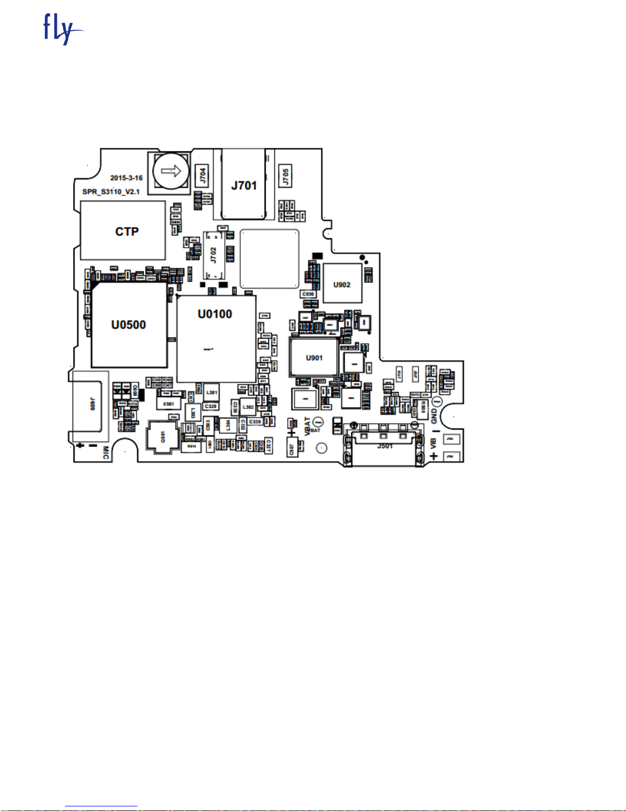
1.3 Mainboard component distribution diagram.......................................................................5
1.4 Main IC Names...................................................................................................................7
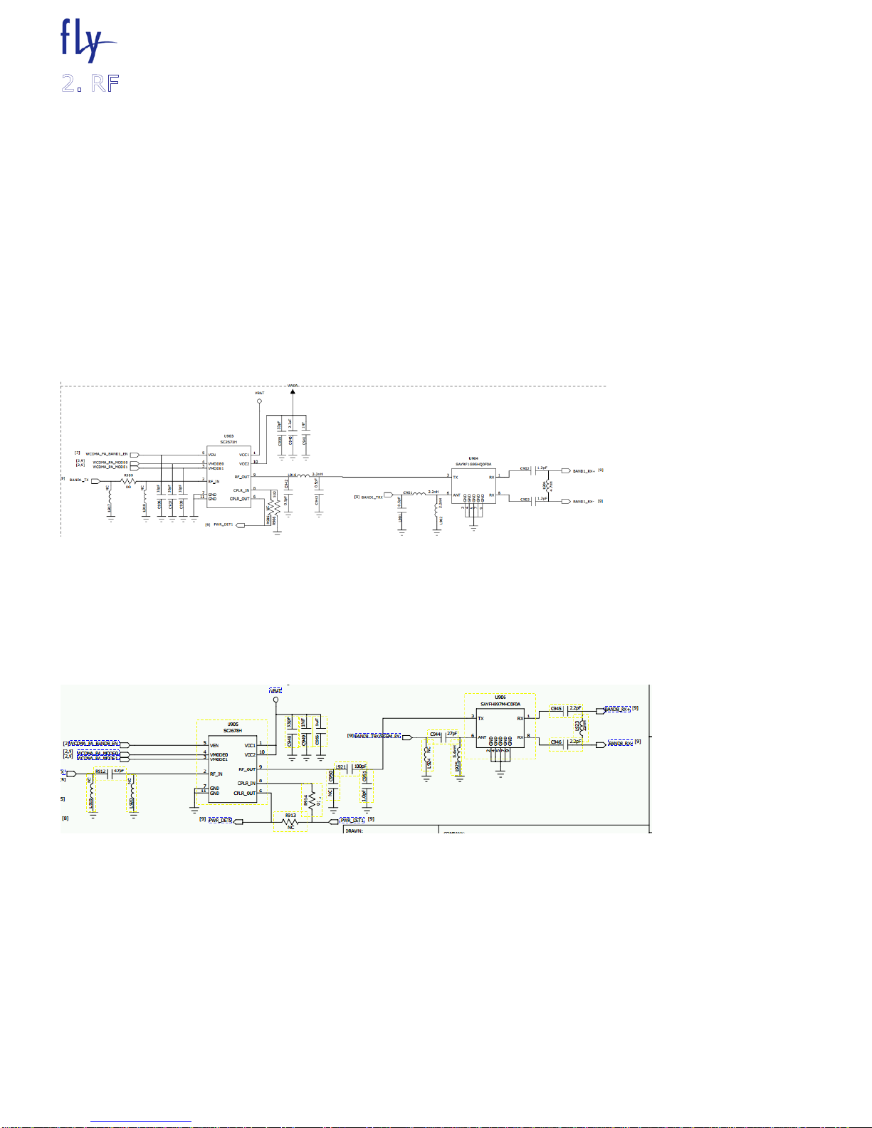
2. RF.........................................................................................................................................8
2.1 WCDMA RF power trouble................................................................................................8
2.2 GSM RF power trouble........................................................................................................9
2.3 WCDMA RX trouble........................................................................................................11
2.4 GSM RX trouble...............................................................................................................12
2.5 WiFi/BT/BT Part .............................................................................................................14
3. Baseband section ..................................................................................................................7
3.1 Outline..............................................................................................................................16
3.2 Common Failure Analysis and Maintenance....................................................................17
3.2.1 Power failure Check..............................................................................................17
3.2.2Audio faults...........................................................................................................18
3.2.3 LCD Fault..............................................................................................................22
3.2.4 FM.........................................................................................................................23
3.2.5 Camera fault...................................................................................................................24
3.2.6 SIM card failure ....................................................................................................25
3.2.7Motor test is invalid...................................... Ошибка! Закладка не определена.
3.2.8 Gravity Sensor.......................................................................................................26
3.2.9 T-Flash fault...........................................................................................................27
3.2.10Touch Panel function............................................................................................27
3.2.11 Cannot boot failure..............................................................................................28

FLY SERVICE SUPPORT
1. FS501 key features
1.1 FS501 brief introduction
The development and design of the FS501 PCBA is based on SC7731G platform. The mainboard system mainly
consists of the chip SC7731G+SR2351C +SR3131, which are responsible for three part functions, namely, baseband,
radio frequency and GPS/WIFI/BLUETOOTH/FM chip. FS501 PCBA is an all-in-one phone mainboard, which supports
GSM, WCDMA, and covers Bluetooth, WIFI, GPS, Camera, FM functions, and so forth.
The maintenance of mainboard is one of the important links among mobile products rear-end producing. The
speed and quality of maintenance relate to the rate of good products, production efficiency, and cost control
throughout the producing. In the case of a reasonable design of product, in the end-producing, finding the significant
proportion in the bad board should be SMT bad and component incoming material bad. So, when maintaining, first,
start with the two aspects. The principal means of fault diagnosis are: (1) find that bad welding spots or components
by microscopic examination and visual inspection; (2) guess failure positions from the fault phenomena; (3) confirm
the fault units by signal detection.
1.2 Function diagram

FLY SERVICE SUPPORT
1.3 Mainboard component distribution diagram
Mainboard TOP

FLY SERVICE SUPPORT
Mainboard BOTTOM

FLY SERVICE SUPPORT
1.4 Main IC Names
Num
ber
Name
Product model
location
1
SC7731G;SC7731G;597;FCVFBGA;13.3X12.1;040;BB
;WCDMA
SC7731G
U0100
2
MEM,P-VFBGA162,4GB/4Gb,6/1.9nS,e-
MMC/LPDDR2,4Gbx8/128Mx32,1.8V/3.3V,MCP,1.8/1
.2V,13*11.5*1.0
TYC0FH121638RA
U0500
4
SR2351C;38;QFN;5.5x4.5;040;RF
SR2351C
U801
5
SR2319A;16;QFN;2.5*2.5;050;
SR2319A
U803
6
SAW滤波器-1575.42MHZ-0.9DB-1.4*1.1*0.6
SAFEB1G57KE0F00
U805
U806
7
LNA;GPS/GNSS;1x1.5x0.75mm
MXDLN16G
U807
9
XTL,TCXO,SMT,26.000MHz,0.5PPM
1.8V,2.5x2x0.8mm
NT2520SB-ENG3216E
Y801
10
Multilayer Chip Band-Pass Filters -2.4GHz
BF2012-L2R4-NBA-
T/LF
U808
11
SR3131;50;QFN; 5.5x7; 040; RF; 3G
transceiver
SR3131
U901
12
SAW FILTER FOR GSM900 (Rx)
SAFEA942MFL0F00R1
4
Z901
13
SAW FILTER FOR GSM1800/GSM1900 (Rx)
SAWEN1G84CV0F00
Z907
14
PA QuadBand GSM/GPRS and Dual-Band WCDMA
Handsets
•LGA 6mm x6mm x0.9mm
SC2662H
U902
15
PA Module for
WCDMA/HSDPA/HSUPA/HSPA+Application
•3mm*3mm*0.9mm
SC2671H
U903
PA Module for
WCDMA/HSDPA/HSUPA/HSPA+Application
•3mm*3mm*0.9mm
SC2678H
U905
FLT,DUPLEXER,SMT,925/960MHz,882.4/912.6MHz,2
x1.6x0.55mm 2.5dB,1.5dB,UMTS?BAND8
SAYFH897MHC0F0A
U906
16
SAW DUPLEXER FOR UMTS BC1
SAYRF1G95HQ0F0A
U904

FLY SERVICE SUPPORT
2.1 WCDMA RF power trouble
Check points
-PA connector soldering
-Duplexer connector soldering
-Other Tx RF Component soldering
Wcdma Band I
Wcdma Band VIII

FLY SERVICE SUPPORT
Start
Replace PA
Check PA
connector
soldering is ok?
Yes
Check Dupolexer
connector is ok?
No Resoldering
No Resoldering
Yes
Check Other Tx RF
components
soldering is ok? No Resoldering
2.2 GSM RF power trouble
Check points
-Tranceiver connector soldering
-PA connector soldering

FLY SERVICE SUPPORT

FLY SERVICE SUPPORT
2.3 WCDMA RX trouble
Check points
-Tranceiver connector soldering
-Duplexer connector soldering
-ASM switch connector soldering
-Other Rx RF Component (L/C) soldering

FLY SERVICE SUPPORT
Start
Check Traceiver
connector
soldering is ok?
Yes
Check Duplexer
connector is ok?
No Resoldering
No Resoldering
Yes
Check Other ASM
Switch soldering is
ok? No Resoldering
Check Other
components(L/C)
soldering

FLY SERVICE SUPPORT
2.4 GSM RX trouble
Check points
-Tranceiver connector soldering
-ASM switch connector soldering
-Rx SAW filter connector soldering
-Other Rx RF Component (L/C) soldering

FLY SERVICE SUPPORT
Start
Check Traceiver
connector
soldering is ok?
Yes
Check ASM Switch
is ok?
No Resoldering
No Resoldering
Yes
Check Rx SAW
filter soldering is
ok? No Resoldering
Check Other
components(L/C)
soldering

FLY SERVICE SUPPORT
2.5 WiFi/BT/GPS Part
2.5.1 WIFI/BT/GPS Part

FLY SERVICE SUPPORT
WIFI BT share RF access, signal is entered by antenna, through U808 2.4GHZ filter, filter sideband unwanted
signal. The clock uses 26M clock provided separately. Data transfer interface and audio interface are directly
connected to the CPU. Interface has SDIO is used for the WIFI signal transmission; PCM is used for the BT signal
transmission.
WIFI main problems:
1. SR2351C chip has been calibrated before out of factory, production line directly do FT test. The probability that it
appears problems by WiFi test is very low, the FT failure problems, please power off and restart the phone, first
retest.
2. Wifi power test fail, please re-test, failed again to check whether the devices U808 on the launch access has
solder skips, and channel RC device.
3. WIFI test EVM fail. This major and power, as well as the freq error, if the power is too high or the freq too big
EVM may also lead to excessive, please re-test.
4. WIFI RX fail, main receiving sensitivity fails to pass, check whether U803 has solder skips. Generally, production
line testing has not shielded box, RX vulnerable to external signal interference, If come across such problems, can
change the channel to do the test.
Bluetooth main problem:
Bluetooth does not need calibration, only need to check the function, if unable to search the device or Bluetooth
can not be opened, check whether the U801 is welding bad or body bad.
GPS main problem:
GPS signal first enters the GPS saw U805 and U806, after saw, input to SR2351 chip within, demodulate signal .
The GPS fails to search satellite or the search- satellite GPS_REG_ON value is high, focus on checking the U805 and
U806 filters paste partial or Weld, then check the tcxo power supply of VDDRF0, four voltage normal check whether
the UART single working. If the power supply and may UART no working ,please check the MCP SR2351.

FLY SERVICE SUPPORT
3.1 Outline
Baseband circuit completes main functions: the procedure data storage, keyboard input, and
the communication between the RF module, RF power control, the control of the power management
module, RUIM card interface, serial download interface, Camera, T-flash, Bluetooth, and MMI
(man-machine interface, such as the display, backlight, buzzer, speaker, microphone, motors,
etc.).
3.1.1 Memory
The baseband part has an eMMC/LPDDR2 MCP. Wherein the amount of eMMC storage 4GB, it stores
a communication protocol layer and application layer software, and storing various system
parameters, calibration parameters, such as RF control correction value of an audio signal, the
IMEI number, and other important information and store user settings data such as phone number,
CALL volume, and tone; LPDDR2 memory 512MB, temporary variables stored phone program run。
3.1.2 Battery
2000mAh 3.7V lithium-ion battery.
3.1.4 32KHzCrystal
32KHz crystal is used for power-saving mode and real-time clock。
If Xtal defective phone just entering the power saving mode will be closed。
3.1.5 SIM Card
SIM card interface is SIM card interface provided by SC7731G.
3.1.6 Audio frequency
The microphone is omnidirectional capacitor type. The largest impedance is 2.2K。
Headset as a standard 3.5mm headphone jack port, the nominal resistance 32。
Speaker adopts 11*15 specification, Receiver adopts 12*06 specification.

FLY SERVICE SUPPORT
3.1.7 I/O Interface
I/O Connector MICRO USB interface standard. Mainly used for software, download picture
messages。
3.1.8 Display
The main screen is 5.0 inch。5.0-inch color screen FWVGA
3.2 Common Failure Analysis and Maintenance
Before cutting board after the completion of the production line SMT X-RAY inspection, according to the actual
situation, X-RAY examination can not be found 100% badness, X-RAY inspection may omissions some fault plate flow
down. If found fault plate in the testing process, the first step is to re-check of the X-RAY and carefully to see if there
is even welding, lap welding, Weld, if normal, analyze the situation following the positioning。
3.2.1 Power failure Check
The failure phenomenon caused by a power failure: can not boot, shutdown leakage current boot large current.
The main reason for the problem: Weld, electrical the original filtering or ESD device to short-circuit, burning with the
device is connected to a power source.
Positioning as well as steps to solve this type of problem is as follows:
1,Troubleshoot and connected to the power supply components of the welding, Weld, or the peripheral devices
even tin。
2,with a multimeter rule out whether there is power to short-circuit, and step by step to troubleshoot the cause
of the short (mainly: even tin, IC burned ESD protection device breakdown, capacitor breakdown)。
3,boot to test the power output is normal。
If a power output value is not normal, whether the view filter capacitor welding problems, whether the
breakdown, filter capacitor is broken, replace; excluded one by one, and finally you can navigate to the main chip
damage。
Each the power test position and the normal boot value is shown in the following table
VDDCORE
1.1V
VDDARM
1.2V
VDDMEM
1.2V

FLY SERVICE SUPPORT
3.2.2 Audio faults
The audio part has main four parts including the speaker, receiver, mic and headphone.
First undesirable phenomena distinguish what part of the problem, and then analyzed according
to the following respective module.
(1)Speaker loop
The FS501 phone’s speaker circuit is as follow
Speaker Loop
Speaker Common faults and reasons:
1,SPK Ringtones reasons:
1) light board, SPK itself is bad, or the connection FPC problem, the whole observation board board PFC Cartridge is
skew, not in place
2) relevant component there is dry welding
3 ) software problems
2,SPK ringtones or murmur:
1) software volume settings
2) SPK ontology reasons
3,Switch machine ringtones, but engineering tests SPK OK:
1) scene mode is set to switch machine ringer off

FLY SERVICE SUPPORT
2) software problems, itself boot ringtones;
(2) Receiver circuit
FS501 phone receiver is embedded in the mobile phone front shell through shrapnel and motherboard connection.
Mainly used for the call. Receiver circuit diagram as shown below.
Receive Loop
Receiver Common faults and reasons:
1, Receiver without sound:
1) Receiver assembly adverse, the shrapnel and board poor contact
2) Receive ontology bad
3) the volume settings or software problems
2, Receiver noise or volume:
1) Receiver incoming material, whether caused by pad short circuit
2) relevant components have solder skips
3) software problems
(3) Mic loop
The AW660A contains two MIC circuits, the main MIC and headphone MIC. The main MIC was inserted
needle. Loop schematic diagram as following:
Main MIC common faults and causes
1 MIC unable to send words or recording:

FLY SERVICE SUPPORT
1) MIC poor welding
2) MIC body bad
2 MIC noise or sound:
1) MIC ontology bad
2) software problems.
Main MIC
(4)Headphone loop
FS501 phone use headphones with a standard 3.5mm headphone. Its circuit diagram is as follows:
Headphones common faults and reasons:
1, headphones only one channel sound:
1) the headset is not inserted in place
2) Relevant component Weld
3) Relevant component breakdown shorted to ground;
2, headphone left and right channels are no sound:
1) the headset is not inserted in place
2) Relevant component breakdown on the short circuit
This manual suits for next models
1
Table of contents
Other FLY Cell Phone manuals