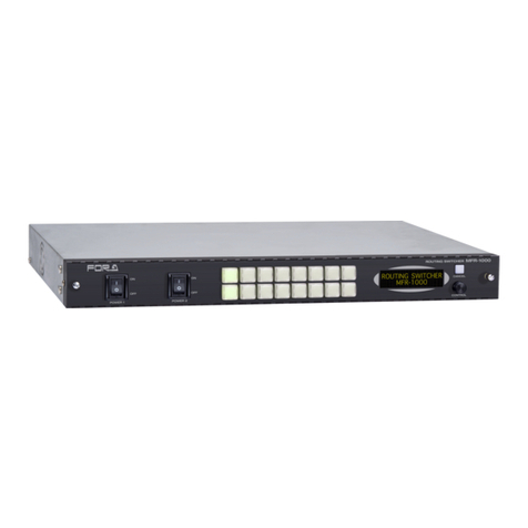
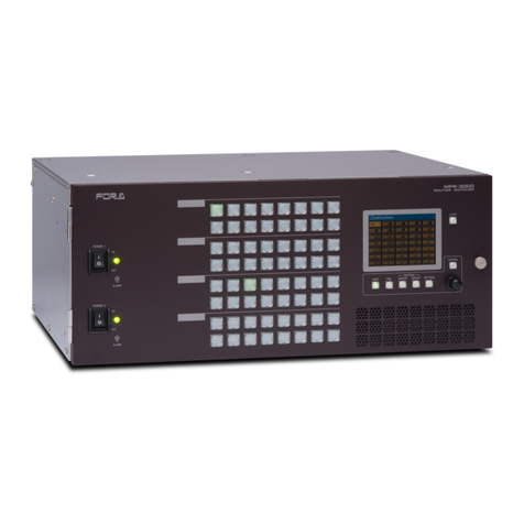
FOR-A MFR-3100EX User manual

MFR-3100EX
Multi Format Routing Switcher
MFR-GPI
MFR-TALM
1st Edition –Rev. 1
USER MANUAL

2
Precautions
Important Safety Warnings
[Power]
Caution
Operate unit only at the specified supply voltage.
Disconnect the power cord via the power plug only. Do not pull on the cable portion.
Stop
Do not place or drop heavy or sharp-edged objects on the power cord. A damaged
cord can cause fire or electrical shock hazards. Regularly check the power cord for
excessive wear or damage to avoid possible fire / electrical hazards.
Caution
Ensure the power cord is firmly plugged into the AC outlet.
[Grounding]
Caution
Ensure the unit is properly grounded at all times to prevent electrical shock.
Hazard
Do not ground the unit to gas lines, units, or fixtures of an explosive or dangerous
nature.
[Operation]
Hazard
Do not operate the unit under hazardous or potentially explosive atmospheric
conditions. Doing so could result in fire, explosion, or other hazardous results.
Hazard
Do not allow liquids, metal pieces, or other foreign materials to enter the unit. Doing
so could result in fire, other hazards, or a unit malfunction.
If a foreign material does enter the unit, turn the power off and immediately disconnect
the power cord. Remove the material and contact an authorized service representative
if damage has occurred.
[Transportation]
Hazard
Handle with care to avoid impact shock during transit, which may cause malfunction.
When you need to transport the unit, use the original or suitable alternative packing
material.

3
[Circuitry Access]
Do not remove covers, panels, casing, or access the circuitry with power applied to
the unit. Turn the power off and disconnect the power cord prior to removal. Internal
servicing / adjustment of unit should only be performed by qualified personnel.
Stop
Do not touch any parts / circuitry with a high heat factor.
Capacitors can retain enough electric charge to cause mild to serious shock, even after
the power has been disconnected. Capacitors associated with the power supply are
especially hazardous.
Hazard
Unit should not be operated or stored with cover, panels, and / or casing removed.
Operating the unit with circuitry exposed could result in electric shock / fire hazards or
a unit malfunction.
[Potential Hazards]
Caution
If abnormal odors or noises are noticed coming from the unit, immediately turn the
power off and disconnect the power cord to avoid potentially hazardous conditions. If
problems similar to the above occur, contact an authorized service representative
before attempting to operate the unit again.
[Ground Terminal, and Rubber Feet]
Caution
To ground the unit, or to install rubber feet, do not use screws or materials other than
those supplied. Doing so may cause damage to the internal circuits or components of
the unit. If you remove the rubber feet that are attached to the unit, do not reinsert the
screws that secure the rubber feet.
[Consumables]
Caution
Consumable items that are used in the unit must be periodically replaced. For further
details on which parts are consumables and when they should be replaced, refer to
the specifications at the end of the Operation Manual. Since the service life of the
consumables varies greatly depending on the environment in which they are used,
such items should be replaced at an early date. For details on replacing consumable
items, contact your dealer.

4
Lighttpd
Copyright © 2004, Jan Kneschke, incremental. All rights reserved.
Redistribution and use in source and binary forms, with or without modification, are permitted provided that the following
conditions are met:
- Redistributions of source code must retain the above copyright notice, this list of conditions and the following disclaimer.
- Redistributions in binary form must reproduce the above copyright notice, this list of conditions and the following disclaimer in
the documentation and/or other materials provided with the distribution.
- Neither the name of the 'incremental' nor the names of its contributors may be used to endorse or promote products derived
from this software without specific prior written permission.
THIS SOFTWARE IS PROVIDED BY THE COPYRIGHT HOLDERS AND CONTRIBUTORS "AS IS" AND ANY EXPRESS OR
IMPLIED WARRANTIES, INCLUDING, BUT NOT LIMITED TO, THE IMPLIED WARRANTIES OF MERCHANTABILITY AND
FITNESS FOR A PARTICULAR PURPOSE ARE DISCLAIMED. IN NO EVENT SHALL THE COPYRIGHT OWNER OR
CONTRIBUTORS BE LIABLE FOR ANY DIRECT, INDIRECT, INCIDENTAL, SPECIAL, EXEMPLARY, OR CONSEQUENTIAL
DAMAGES (INCLUDING, BUT NOT LIMITED TO, PROCUREMENT OF SUBSTITUTE GOODS OR SERVICES; LOSS OF
USE, DATA, OR PROFITS; OR BUSINESS INTERRUPTION) HOWEVER CAUSED AND ON ANY THEORY OF LIABILITY,
WHETHER IN CONTRACT, STRICT LIABILITY, OR TORT (INCLUDING NEGLIGENCE OR OTHERWISE) ARISING IN ANY
WAY OUT OF THE USE OF THIS SOFTWARE, EVEN IF ADVISED OF THE POSSIBILITY OF SUCH DAMAGE.
Libjpeg
This software is copyright (C) 1991-2022, Thomas G. Lane, Guido Vollbeding. All rights reserved.
This software is based in part on the work of the Independent JPEG Group.
* All other copyrights are property of their respective owners.

5
Upon Receipt
MFR-3100EX units and their accessories are fully inspected and adjusted prior to shipment. Check your
received items against the packing lists below. Check to ensure no damage has occurred during
shipment. If damage has occurred, or items are missing, inform your supplier immediately.
◆MFR-3100EX Box
ITEM
QTY
REMARKS
MFR-3100EX
1
AC Cord
1 set
AC cord clamp included (See next page for
installation instructions)
Rubber Feet
1
Setup Guide
1
◆Input / Output Cards
ITEM
QTY
REMARKS
MFR-8SDI
1 - 8 *
SDI/digital audio input card (SDI/MADI x 8ch)
MFR-8SDO
1 - 8 *
8 SDI output card
MFR-8AAI
1 - 8 *
Analog audio input card with A/D converter
(Analog 8 stereo pairs)
MFR-8AAO
1 - 9 *
Analog audio output card with D/A converter
(Analog 8 stereo pairs)
MFR-8AESI
1 - 8 *
AES/EBU audio input card
(AES/EBU 8 stereo pairs)
MFR-8AESO
1 - 9 *
AES/EBU audio output card
(AES/EBU 8 stereo pairs)
MFR-16MV
1 - 4 *
16 SDI output card with multiviewer function.
MFR-8SDIGB
1 - 8 *
SDI input card (Gearbox 2ch built-in)
MFR-8SDOGB
1 - 9 *
SDI output card (Gearbox 2ch built-in)
MFR-8MADIPO
1 - 9 *
Digital audio/video output card
(w/ audio mapping) (MADI/SDI x 8ch)
MFR-8AESPO
1 - 9 *
Digital audio output card
(w/ audio mapping) (AES/EBU 8 stereo pairs)
MFR-8SDODL
1 - 9 *
8 SDI output card (w/ AVDL function)
* The number of installed cards varies depending on the system configuration. See the Matrix Size
Chart on Sec. 2-1-1.

6
◆Options (for MFR-3100EX)
ITEM
QTY
REMARKS
MFR-31CPU
1
Redundant CPU card *
MFR-31PS
1 set
Redundant power supply unit (with AC cord and AC
cord clamp.)
MFR-8RUA/18RUA/39RUA
MFR-40RU
MFR-16RU/16RUD/16RUTA
MFR-16/32/64RUW
1
Remote Control Unit
◆Interface Expansion Unit
ITEM
QTY
REMARKS
MFR-GPI
1
AC Adaptor
1
With DC lock plug
AC Cord
1
EIA Rack Mount Brackets
1 set
LAN Cable (straight)
1
◆Tally Manager Unit
ITEM
QTY
REMARKS
MFR-TALM
1
AC Adaptor
1
With DC lock plug
AC Cord
1
EIA Rack Mount Brackets (optional)
1 set
Single- or Dual-unit type
◆MFR-RULINK Unit
ITEM
QTY
REMARKS
MFR-RULINK
1
AC Adaptor
1
With DC lock plug
AC Cord
1
EIA Rack Mount Brackets (optional)
1 set
Single- or Dual-unit type

7
AC Cord Clamp Installation
1) Insert the anchor into the hole next to the AC inlet.
2) Plug in the AC cord.
3) Adjust the strap length to fit.
4) Wrap the AC cord clamp around the AC cord.
5) Gently pull on the AC cord to ensure it has been securely plugged in.
Font Conventions
The following conventions are used throughout this manual:
References to the MFR-3100EX Web-based Control Software are indicated by [Web-based
Control: XXX page].
3)
1)
2)
4)

8
Table of Contents
1. Prior to Starting.................................................................................................................................. 10
1-1. Overview .................................................................................................................................. 10
1-2. Features................................................................................................................................... 10
2. Panel Descriptions............................................................................................................................. 11
2-1. MFR-3100EX Front Panel........................................................................................................ 11
2-1-1. Matrix Size Chart .............................................................................................................. 11
2-2. MFR-3100EX Rear Panel ........................................................................................................ 13
2-2-1. Interfaces .......................................................................................................................... 15
2-2-2. SDI Input/ Output Cards Installation and Removal........................................................... 16
2-2-3. MFR-31CPU Card Installation and Removal.................................................................... 16
2-3. SDI Input / Output Cards.......................................................................................................... 17
2-3-1. MFR-8SDI......................................................................................................................... 17
2-3-2. MFR-8SDO ....................................................................................................................... 17
2-3-3. MFR-16MV........................................................................................................................ 18
2-3-4. MFR-8SDIGB.................................................................................................................... 18
2-3-5. MFR-8SDOGB.................................................................................................................. 19
2-3-6. MFR-8SDODL................................................................................................................... 19
2-4. Audio Input / Output Cards....................................................................................................... 20
2-4-1. MFR-8AAI (Analog Input) ................................................................................................. 20
2-4-2. MFR-8AAO (Analog Output)............................................................................................. 21
2-4-3. MFR-8AESI (AES/EBU Input)........................................................................................... 23
2-4-4. MFR-8AESO (AES/EBU Output)...................................................................................... 23
2-4-5. MFR-8SDI (MADI Input) ................................................................................................... 24
2-4-6. MFR-8MADIPO (MADI/SDI Output) ................................................................................. 24
2-4-7. MFR-8AESPO (AES/EBU Output).................................................................................... 26
2-5. MFR-GPI.................................................................................................................................. 27
2-5-1. Front Panel ....................................................................................................................... 27
2-5-2. Rear Panel........................................................................................................................ 28
2-5-3. Interfaces .......................................................................................................................... 29
2-5-4. Switches on the Card........................................................................................................ 31
2-6. MFR-TALM............................................................................................................................... 32
2-6-1. Front Panel ....................................................................................................................... 32
2-6-2. Rear Panel........................................................................................................................ 33
3. System Configuration Example......................................................................................................... 34
3-1. Basic Configuration.................................................................................................................. 34
3-2. Main Unit Linking...................................................................................................................... 35
3-2-1. Parallel Link System Example.......................................................................................... 35
3-2-2. Expanded Matrix System Example................................................................................... 36
3-3. Signal Name and Tally Link System ........................................................................................ 37
3-3-1. Standard Configuration..................................................................................................... 37
3-3-2. If Configuring an MFR-TALM............................................................................................ 39
3-4. Switcher's AUX Crosspoints Switching System....................................................................... 42
3-4-1. Switching an AUX Bus Signal........................................................................................... 42
3-4-2. Synchronous Crosspoints Switching ................................................................................ 44
4. Multiview Output................................................................................................................................ 45
4-1. Multiviewer Specifications........................................................................................................ 45
4-2. FS Mode................................................................................................................................... 46
4-3. Displaying Multiview Images.................................................................................................... 47
4-4. Basic Rules for Creating Multiview Layouts............................................................................. 47
4-5. Clocks....................................................................................................................................... 48
4-6. Available Window Objects........................................................................................................ 49
5. Gearbox Feature (MFR-8SDIGB/8SDOGB)...................................................................................... 50
9
5-1. MFR-8SDIGB / 8SDOGB Cards .............................................................................................. 50
5-2. Available Conversions.............................................................................................................. 51
5-3. Conversion Settings................................................................................................................. 51
5-3-1. Converting 3G SQD Input to 2SI (MFR-8SDIGB)............................................................. 51
5-3-2. Converting 2SI to SQD Output (MFR-8SDOGB).............................................................. 52
5-3-3. Converting 12G-SDI Input to 3G-SDI 2SI (MFR-8SDIGB)............................................... 53
5-3-4. Converting 3G-SDI SQD to 12G-SDI Output (MFR-8SDOGB)........................................ 53
5-3-5. Payload ID ........................................................................................................................ 54
5-3-6. 3G-SDI BNC Output Settings ........................................................................................... 55
6. AVDL Function (MFR-8SDODL) ....................................................................................................... 56
6-1. Output Format.......................................................................................................................... 56
6-2. Quiet Switch............................................................................................................................. 56
6-3. Additional Delay to Output ....................................................................................................... 57
6-4. MFR-8SDODL Support Formats.............................................................................................. 57
7. Serial / LAN Command Control......................................................................................................... 58
7-1. Serial Interface......................................................................................................................... 58
7-2. LAN Interface ........................................................................................................................... 58
7-3. Control Command.................................................................................................................... 59
7-3-1. Command Responses (Commands 1-6).......................................................................... 61
7-3-2. Receiving Responses (Commands 1-6)........................................................................... 62
7-3-3. Channel Name Request Commands (7) .......................................................................... 65
7-3-4. CPU Status Request Command (8) ................................................................................. 69
7-3-5. Destination Lock Status Request Command (9) .............................................................. 70
7-3-6. Channel Name Import Commands (10)............................................................................ 71
7-3-7. System Size Request Command (11) .............................................................................. 71
7-3-8. Video Format Commands (12) ......................................................................................... 72
7-3-9. Audio Input Setting Command (13) .................................................................................. 73
7-3-10. Audio Channel Mapping Command (14) ........................................................................ 74
7-3-11. Link Enable / Disable Command (15)............................................................................. 75
7-3-12. Video Format and Output Delay Command (16)............................................................ 75
8. Troubleshooting................................................................................................................................. 77
9. Specifications and Dimensions ......................................................................................................... 78
9-1. Unit Specifications.................................................................................................................... 78
9-1-1. MFR-3100EX.................................................................................................................... 78
9-1-2. MFR-GPI........................................................................................................................... 80
9-1-3. MFR-TALM ....................................................................................................................... 81
9-2. External Dimensions................................................................................................................ 82
9-2-1. MFR-3100EX.................................................................................................................... 82
9-2-2. MFR-GPI........................................................................................................................... 83
9-2-3. MFR-TALM ....................................................................................................................... 84

10
1. Prior to Starting
1-1. Overview
The MFR-3100EX is a multi-format routing switcher that supports 12G-SDI (When MFR-8SDIGB/
8SDOGB are installed), 3G-SDI, HD-SDI, SD-SDI, ASI, AES/EBU, MADI and analog audio signals.
Inside the 4U case a matrix of up to 64 inputs/72 outputs can be configured. And by linking multiple
units, they can be used as a large-scale routing switcher. It supports various functions such as the
capability of linking multiple cases, tally connections with peripheral devices, and automatic source
name tracking, to allow the units to be the core product in small to medium size systems.
1-2. Features
➢Support for 3G-SDI, HD-SDI, SD-SDI, and ASI signals with automatic signal recognition that
enables operation without concern for the type of signal. 12G-SDI, AES/EBU, MADI and
analog audio input/output and multiview output are also supported by installing optional
input/output cards.
➢By linking multiple units, they can be used as a large-scale routing switcher.
➢Up to 2 units can be linked together.
➢One routing switcher can be virtually partitioned to build any theoretical hierarchy, which
creates possibilities for use in various operating forms.
➢Various crosspoint control functions such as Salvo, Take, Link, Level, and Chop operation.
➢Tally linking with FOR-A’s video switchers (HANABI Series) and multi viewers. Source name
displays on video switchers and multi viewers can be switched in conjunction with switching
controlled in the main unit. MFR routers support TSL and Harris protocol, enabling linkage to
other companies' products.
➢Built-in web server for remote control through a web browser
➢SNMP support enabling SNMP monitoring system configuration
➢Status monitoring for power supply, fan, CPU as well as crosspoint errors and etc.
➢CPU board redundancy allowing monitoring of primary CPU board operation via the
secondary board. Immediate and smooth switch over to the secondary board without down
time in case of irregularities, as well as stable remote control operation supported by the
network redundancy
➢Power unit redundancy for stable power supply against power unit failure or power supply
troubles
➢Matrix partition and level setting capabilities by remote control units support a flexible control
environment (maximum of 128 units in total including the main unit)
➢Remote control panel connectivity for configuring a huge control panel
➢Interface expansion unit (MFR-GPI) for additional 128 (32 x 4) GPI/O and 4 serial ports (9-pin
D-sub, male)
➢MFR-TALM Tally Manager Unit is designed specifically to manage tally and signal name data
in the MFR system and the exchange of this data with external devices such as a video
switcher, multiviewer etc. The unit performs the task of tally data computation, which is
ordinarily undertaken by the MFR main unit, to accelerate the task.
➢Conversions between 12G-SDI and Quad Link 3G-SDI and between 2SI and SQD available
by installing optional MFR-8SDIGB and MFR-8SDOGB (Gearbox feature built-in) cards.
➢MFR-8SDODL option card (w/ AVDL function) allows up to 5H phase adjustment against
reference.
➢The MFR-RULINK connects MFR main units to MFR remote control units that are located in
distant locations. Operations such as Crosspoint switching or Lock can be performed with
MFR-RULINK using MFR remote control units from a distant location.

11
2. Panel Descriptions
The assigned CPU and LAN port numbers for MFR-31CPU and MFR-3100EX are shown in the table
below.
CPU1/2
Primary/ Secondary
MFR-LAN1/2
PC-LAN1/2
MFR-31CPU
CPU1
Primary CPU
MFR-LAN1
PC-LAN1
MFR-3100EX
CPU2
Secondary CPU
MFR-LAN2
PC-LAN2
2-1. MFR-3100EX Front Panel
Char.
Name
Description
A
POWER1
Power switch 1 (standard equipment)
(1) Switch to turn unit power On/Off.
(2) DC power supply voltage indication LED
(Normal: lit green / Error: unlit)
(3) ACTIVE CPU LED (ACTIVE CPU: lit green/
Non-ACTIVE CPU: unlit)
(4) REF IN LED (Locked to external reference signal: lit green
Not locked or no reference signal: unlit)
(5) Alarm indication LED (Normal: unlit /
Power or fan error, Secondary CPU active: lit)
B
POWER2
Power switch 2 (optional equipment) (1), (2), (3), (4) and (5) the same
as POWER1.
2-1-1. Matrix Size Chart
◆Standard SDI Signal Routing
The number of installed MFR-8SDI, MFR-8SDO and MFR-8SDODL cards determines the
matrix size.(64 x 72 to 8 x 8)
Number of cards: MFR-8SDO, MFR-8SDODL
9
8
7
6
5
4
3
2
1
Number of
cards:
MFR-8SDI
8
64 x 72
64 x 64
64 x 56
64 x 48
64 x 40
64 x 32
64 x 24
64 x 16
64 x 8
7
56 x 72
56 x 64
56 x 56
56 x 48
56 x 40
56 x 32
56 x 24
56 x 16
56 x 8
6
48 x 72
48 x 64
48 x 56
48 x 48
48 x 40
48 x 32
48 x 24
48 x 16
48 x 8
5
40 x 72
40 x 64
40 x 56
40 x 48
40 x 40
40 x 32
40 x 24
40 x 16
40 x 8
4
32 x 72
32 x 64
32 x 56
32 x 48
32 x 40
32 x 32
32 x 24
32 x 16
32 x 8
3
24 x 72
24 x 64
24 x 56
24 x 48
24 x 40
24 x 32
24 x 24
24 x 16
24 x 8
2
16 x 72
16 x 64
16 x 56
16 x 48
16 x 40
16 x 32
16 x 24
16 x 16
16 x 8
1
8 x 72
8 x 64
8 x 56
8 x 48
8 x 40
8 x 32
8 x 24
8 x 16
8 x 8
POWER 1
ON
OFF ALARM
CPU2
ACTIVE
CPU1
REF INPOWER
POWER 2
ON
OFF ALARM
CPU2
ACTIVE
CPU1
REF INPOWER
ROUTING SWITCHER
MFR-3100EX
A
(1)
(2)
(3)
B
(4)
(5)

12
MFR-16MV cards can also be installed to the router. A single MFR-16MV card provides 16
outputs (using two slots) and supports two multiview channels. To output multiview images, a
multiview channel (MV OUT1 or MV OUT2) needs to be directly assigned to output ports.
Instead of multiview images, you can also assign any destination channel to output ports as a
single image.
◆12G-SDI Signal Routing
12G-SDI signal routing is enabled by installing MFR-8SDIGB and MFR-8SDOGB cards and
using them for 12G-SDI input/output. (If using MFR-8SDIGB and MFR-8SDOGB for 3G-SDI
input/output, the “Standard SDI Signal Routing” table in the previous page applies.)
The number of installed MFR-8SDIGB and MFR-8SDOGB cards determines the matrix size.
(16 x 18 to 2 x 2)
Number of cards: MFR-8SDOGB (12G-SDI output)
9
8
7
6
5
4
3
2
1
Number of
cards
MFR-8SDIGB
(12G-SDI
input)
8
16 x 18
16 x 16
16 x 14
16 x 12
16 x 10
16 x 8
16 x 6
16 x 4
16 x 2
7
14 x 18
14 x 16
14 x 14
14 x 12
14 x 10
14 x 8
14 x 6
14 x 4
14 x 2
6
12 x 18
12 x 16
12 x 14
12 x 12
12 x 10
12 x 8
12 x 6
12 x 4
12 x 2
5
10 x 18
10 x 16
10 x 14
10 x 12
10 x 10
10 x 8
10 x 6
10 x 4
10 x 2
4
8 x 18
8 x 16
8 x 14
8 x 12
8 x 10
8 x 8
8 x 6
8 x 4
8 x 2
3
6 x 18
6 x 16
6 x 14
6 x 12
6 x 10
6 x 8
6 x 6
6 x 4
6 x 2
2
4 x 18
4 x 16
4 x 14
4 x 12
4 x 10
4 x 8
4 x 6
4 x 4
4 x 2
1
2 x 18
2 x 16
2 x 14
2 x 12
2 x 10
2 x 8
2 x 6
2 x 4
2 x 2
◆AUDIO Signal Routing
The number of installed audio cards: MFR-8SDI (*1), MFR-8AAI, MFR-8AAO, MFR-8AESI,
MFR-8AESO, MFR-8MADIPO and MFR-8AESPO determines the matrix size.
(The matrix sizes below do not indicate the number of audio channels, but the number of
streams. Use the followings to find the number of audio channels: SDI embedded: 16 channels,
AES/EBU: 2 channels, Analog: 2 channels, MADI: 64 channels)
Number of cards: MFR-8AAO, MFR-8AESO, MFR-8MADIPO or MFR-8AESPO
9
8
7
6
5
4
3
2
1
Number of
cards:
MFR-8SDI
MFR-8AAI
MFR-8AESI
8
64 x 72
64 x 64
64 x 56
64 x 48
64 x 40
64 x 32
64 x 24
64 x 16
64 x 8
7
56 x 72
56 x 64
56 x 56
56 x 48
56 x 40
56 x 32
56 x 24
56 x 16
56 x 8
6
48 x 72
48 x 64
48 x 56
48 x 48
48 x 40
48 x 32
48 x 24
48 x 16
48 x 8
5
40 x 72
40 x 64
40 x 56
40 x 48
40 x 40
40 x 32
40 x 24
40 x 16
40 x 8
4
32 x 72
32 x 64
32 x 56
32 x 48
32 x 40
32 x 32
32 x 24
32 x 16
32 x 8
3
24 x 72
24 x 64
24 x 56
24 x 48
24 x 40
24 x 32
24 x 24
24 x 16
24 x 8
2
16 x 72
16 x 64
16 x 56
16 x 48
16 x 40
16 x 32
16 x 24
16 x 16
16 x 8
1
8 x 72
8 x 64
8 x 56
8 x 48
8 x 40
8 x 32
8 x 24
8 x 16
8 x 8
(*1) Used as MADI input card.

13
2-2. MFR-3100EX Rear Panel
*The above figure shows an MFR-3100EX with MFR-8SDI, MFR-8SDO, MFR-31CPU and
MFR-31PS cards installed.
Char.
Name
Description
A
MFR-LAN
Ethernet ports for connection to MFR Remote Control Units and MFR-
GPI (10/100BASE-TX, RJ-45)
(1) MFR-LAN2 (for MFR-3100EX)
(2) MFR-LAN1 (for MFR-31CPU)
B
PC-LAN
Ethernet ports for connection to PC or other external unit
(10/100/1000BASE-T, RJ-45)
(1) PC-LAN2 (for MFR-3100EX)
(2) PC-LAN1 (for MFR-31CPU)
C
NC
Not used
D
ALARM
Used for alarm output
►See Sec. 2-2-1. "Interfaces."
E
AC IN1
Used to connect Power Supply Unit 1 (standard equipment) to an AC
power source
F
AC IN2
Used to connect Power Supply Unit 2 (optional) to an AC power source
G
INPUT
Used for installing input cards
H
OUTPUT
Used for installing output cards
I
REF IN
Used to input a reference signal (BB or Tri-level sync)
(With loop-through. Terminate with 75-ohm terminator, if unused.)
PS1
PS2
AC100-240V 50/60Hz IN AC100-240V 50/60Hz IN
MFR-3100EX
1
SLOT
3 4
2
MFR-31VP
INPUT OUTPUT
1 2 3 4 5 6 78 1 2 3 4 56 7 8 9
MFR-LAN PC-LAN REF IN ALARM
PS1
PS2
2
3
4
5
6
7
8
1
2
3
4
5
6
7
8
1
2
3
4
5
6
7
8
1
2
3
4
5
6
7
8
1
2
3
4
5
6
7
8
1
2
3
4
5
6
7
8
1
2
3
4
5
6
7
8
1
2
3
4
5
6
7
8
1
2
3
4
5
6
7
8
1
2
3
4
5
6
7
8
1
2
3
4
5
6
7
8
1
2
3
4
5
6
7
8
1
2
3
4
5
6
7
8
1
2
3
4
5
6
7
8
1
2
3
4
5
6
7
8
1
2
3
4
5
6
7
8
1
2
3
4
5
6
7
8
1
MFR-3100EX
AC100-240V 50/60Hz IN
SLOT
INPUT OUTPUT
1 2
MFR-31VP
OUTOUT 98
OUT
7
OUT
6
OUT
MFR-LAN PC-LAN
MFR-31CPU
3 4
1 2 3 4 5 67 8 1 2 3 45 6 7 89
AC100-240V 50/60Hz IN
OUTOUTININININININ 543
OUT
2
OUT
187654321 ININ
MFR-LAN PC-LAN REF IN ALARM
A
(2)
B
(2)
F
01 02 03 04 05 06 07 08 09 10 11 12 13 14 15 16 17
Slot No.
G
H
A
B
D
(1)
I
(1)
E
C
C

14
IMPORTANT
When using the MFR-31CPU, each of the two MFR-LANs should be connected to their respective
devices to enable CPU redundancy. Also, when connecting MFR series devices to LAN, they
should be on a separate network from other systems, such as an internal LAN. Do not use the
spanning tree or other functions that inhibit or restrict communication in MFR-LAN.
Input /output cards and Slots
Char.
Slot
Video card
Audio card
G
INPUT1-8
(No. 01-08)
8SDI / 8SDIGB: Max. 8 cards
8AAI, 8AESI: Max 8 cards
H
OUTPUT1-9
(No. 09-17)
8SDO / 8SDOGB / 8SDODL:
Max. 9 cards
16MV: Max. 4cards *
8AAO, 8AESO,
8MADIPO, 8AESPO:
Max. 9 cards
* Available slot pairs are No. 09-10, 11-12, 13-14, and 15-16.
◆Cooling fans
Four cooling fans are installed in MFR-3100EX units: FAN 1 is on the rear panel and FAN2, FAN
3 and 4 are on the front panel inside as shown below.
Rear Panel
Front Panel Inside
PS1
PS2
AC100-240V 50/60Hz IN AC100-240V 50/60Hz IN
MFR-3100EX
1
SLOT
3 4
2
MFR-31VP
INPUT OUTPUT
1 2 3 4 5 6 78 1 2 3 4 56 7 8 9
MFR-LAN PC-LAN REF IN ALARM
FAN1
FAN2
FAN3
FAN4

15
2-2-1. Interfaces
◆ALARM Connector (9-pin D-sub, female)
Alarm 1 Out:
Under normal operation:
Pins 1 and 6 are open.
In a malfunction or power-off state:
Pins 1 and 6 are closed.
Alarm 2 Out:
Under normal operation:
Pins 2 and 7 are open.
In a malfunction or power-off state:
Pins 2 and 7 are closed.
ALARM Connector Pin Assignments
Pin No.
Signal Name
Description
1
ALARM 1 OUT
Alarm 1 output (Default setting: Fan)
2
ALARM 2 OUT
Alarm 2 output (Default setting: Power)
3
NC
Unused
4
NC
Unused
5
NC
Unused
6
ALARM 1 COMMON
Alarm 1 output, common
7
ALARM 2 COMMON
Alarm 2 output, common
8
GND
Signal ground
9
GND
Signal ground
The following items can be set for ALARM1 OUT and ALARM2 OUT. The alarms can be
assigned in the Web-Based Control.
Available alarm signals
Fan (including power unit cooling fans)
Power
Secondary CPU error
CPU Changeover
(Issued when the secondary CPU is activated to change over the operation)
Crosspoint Error
1
2
7
345
9 68

16
2-2-2. SDI Input/ Output Cards Installation and Removal
MFR-3100EX units allow Input/ Output cards to be installed into slots on the rear panel.
◆Removing input /output cards
To remove an installed card while the MFR-3100EX power is on, turn off the target Slot
Power on the SlotStatus page of Web-based Control and remove the card.
◆Installing input/output cards
(1) Insert an input/ output card into the slot.
(2) Open the SlotStatus page of Web-based Control and if the Slot Power of the inserted
slot is off, turn it ON.
* To power on/ off an installed MFR-16MV card using I/O card power switches, two power
switches (for two slots) must be turned on/ off.
2-2-3. MFR-31CPU Card Installation and Removal
MFR-31CPU cards can be installed or removed with the MFR-3100EX power turned on as
shown below.
IMPORTANT
Do not touch any other parts on the card. Static electricity may damage sensitive electrical
components on the card.
◆Removing an installed MFR-31CPU card
(1) Switch the ACTIVE CPU from the MFR-31CPU to the MFR-3100EX CPU.
(2) Verify that the ACTIVE light for CPU2 on the left side of the front panel is lit.
(3) Disconnect the MFR-31CPU cables connected to the MFR-LAN and PC-LAN.
(4) Open the front panel and release the screw on the right side of the MFR-31CPU.
(5) Pull the MFR-31CPU gently straight out of the slot.
(6) Close the front panel.
* See “Manual Switching of Active CPU” in the Web-based Control Operation Manual.
◆Inserting an MFR-31CPU card
(1) Open the front panel.
(2) Align both edges of the MFR-31CPU with the guide rails in the slot and insert the card.
(3) Verify that the MFR-31CPU is inserted properly, and secure the screw on the right side
of the MFR-31CPU.
(4) Close the front panel.
(5) LAN connect PC-LAN1 and PC-LAN2 to the same network. Similarly, LAN connect MFR-
LAN1 and MFR-LAN2 to the same network.
◆Manually activating the MFR-31CPU
Once an MFR-31CPU is installed, it is NOT automatically activated. Follow the procedure
below to manually activate the MFR-31CPU.
(1) After installing an MFR-31CPU, switch the MFR-31CPU to ACTIVE using Web-based
Control.
(2) Verify that the CPU1 ACTIVE lamp on the left side of the front panel is lit and CPU2
ACTIVE lamp is unlit.

17
2-3. SDI Input / Output Cards
Set up input signals in the Web-based Control Software as shown below.
◆Source Assignment
Open the [Web-based Control: Router System Settings - Source Assignment page].
This page allows you to assign physical inputs to logical input channels.
◆Source Name
Open the [Web-based Control: Router System Settings - Source Name page].
This page allows you to change source names displayed on Remote Controllers or other
devices.
Set up output signals in the Web-based Control Software as shown below.
◆Destination Assignment
Open the [Web-based Control: Router System Settings - Destination Assignment page].
This page allows you to assign physical outputs to logical output channels.
◆Destination Name
Open the [Web-based Control: Router System Settings - Destination Name page].
This page allows you to change destination names displayed on Remote Controllers or other
devices.
2-3-1. MFR-8SDI
MFR-8SDI is an SDI or digital audio input card.
When using as an SDI card, it can accept 8 of 3G/HD/SD-SDI and ASI signals.
When using as a digital audio card, refer to Sec. 2-4-5. “MFR-8SDI (MADI Input)” for details.
Up to 8 cards can be installed into Slot No. 01 to 08.
►See “Input /output cards and Slots” in Sec. 2-2. "MFR-3100EX Rear Panel."
BNC x 8 inputs (3G/HD/SD-SDI or ASI signal auto-detection)
2-3-2. MFR-8SDO
MFR-8SDO is an SDI output card and can output 8 of 3G/HD/SD-SDI and ASI signals.
Up to 9 cards can be installed into Slot No. 09 to 17.
►See “Input /output cards and Slots” in Sec. 2-2. "MFR-3100EX Rear Panel."
BNC x 8 outputs (3G/HD/SD-SDI or ASI signal depending on crosspoint selections)
2
3
4
5
6
7
8
11
IN
1
8
7
6
5
4
3
2
1
OUT

18
2-3-3. MFR-16MV
MFR-16MV is an SDI output card and can output 16 of 3G/HD/SD-SDI and ASI signals.
Up to 4 cards can be installed into Slot No. 09 to 16. Two slots are required for each card.
Any outputs (BNC) on the card are available for multiview channels. 3G/HD-SDI signals can
be output for multiview output.
►See “Input /output cards and Slots” in Sec. 2-2. "MFR-3100EX Rear Panel."
►See Sec. 4. “Multiview Output.”
BNC x 16 outputs (3G/HD/SD-SDI or ASI signal depending on crosspoint selections)
2-3-4. MFR-8SDIGB
The MFR-8SDIGB is an SDI input card that accepts 12G/3G-SDI signals and supports
Gearbox feature in which video signal conversions between 12G-SDI and Quad Link 3G-SDI,
and between 2SI and SQD are available.
►See Sec. 5. “Gearbox Feature (MFR-8SDIGB/8SDOGB).”
The following input combinations are available (Only 1D and 2D BNC connectors can accept
12G-SDI signals):
12G-SDI signal * 2
3G-SDI signal * 8
12G-SDI signal * 1 and 3G-SDI signal * 4
Up to 8 cards can be installed into Slot No. 01 to 08.
►See “Input /output cards and Slots” in Sec. 2-2. "MFR-3100EX Rear Panel."
BNC x 8 inputs (12G/3G-SDI)
Set up input signals in the Web-based Control Software as shown below.
◆Gearbox settings
Open the [(Main Unit Settings) - Gearbox Settings page].
This page allows you to set Gearbox input and output signals, lock mode and delay.
2
3
4
5
6
7
1
8 16
9
10
11
12
13
14
15
1A
1B
1C
12G / 3G-SDI
1D
2A
2B
2C
12G / 3G-SDI
2D

19
2-3-5. MFR-8SDOGB
The MFR-8SDOGB is an SDI output card that accepts 12G/3G-SDI signals and supports
Gearbox feature in which video signal conversions between 12G-SDI and Quad Link 3G-SDI,
and between 2SI and SQD are available.
►See Sec. 5. “Gearbox Feature (MFR-8SDIGB/8SDOGB).”
The following output combinations are available (Only 1D and 2D BNC connectors can accept
12G-SDI signals):
:
12G-SDI signal * 2
3G-SDI signal * 8
12G-SDI signal * 1 and 3G-SDI signal * 4
Up to 9 cards can be installed into Slot No. 09 to 17.
►See “Input /output cards and Slots” in Sec. 2-2. "MFR-3100EX Rear Panel."
BNC x 8 outputs (12G/3G-SDI)
Set up output signals in the Web-based Control Software as shown below.
◆Gearbox settings
Open the [(Main Unit Settings) - Gearbox Settings page].
This page allows you to set Gearbox input and output signals, lock mode and delay.
2-3-6. MFR-8SDODL
The MFR-8SDODL is an SDI output card, allowing up to 5H phase adjustment against
reference.
►See Sec. 6. “AVDL Function (MFR-8SDODL).”
Up to 9 cards can be installed into Slot No. 09 to 17.
►See “Input /output cards and Slots” in Sec. 2-2. "MFR-3100EX Rear Panel."
BNC x 8 outputs (3G/HD-SDI)
Set up output signals in the Web-based Control Software as shown below.
◆AVDL Settings
Open the [(Main Unit Settings) - AVDL Settings page].
This page allows you to set the video format and a delay to be added.
1A
1B
1C
12G / 3G-SDI
1D
2A
2B
2C
12G/ 3G-SDI
2D

20
2-4. Audio Input / Output Cards
Source and destination assignment procedures for audio signals are the same as those for SDI
signals. Refer to Sec. 2-3. “SDI Input / Output Cards.”
This chapter describes audio specific setup. Audio signals should be setup in the Web-based
Control pages
►See [Web-based Control: Audio Settings page].
2-4-1. MFR-8AAI (Analog Input)
MFR-8AAI is an analog audio input card with A/D converter.
Up to 8 cards can be installed into Slot No. 01 to 08.
►See “Input /output cards and Slots” in Sec. 2-2. "MFR-3100EX Rear Panel."
25-pin D-Sub (female) x 2 (8 stereo pairs, 16 channels), 600-ohm or high impedance
◆Analog Audio Input
Select the input impedance and adjust the input level per each stereo pair (2 channels) in the
[Web-based Control: Audio Settings page].
Analog Input Terminal
Select 600-ohm or High impedance for analog audio
input.
Analog Input Termination(*1)
Analog Input Level
Select the analog audio input level for each stereo pair.
Analog Input Ref Level (*1)
Analog Input Adjust Gain (*1)
Adjust analog input signal gain for each stereo pair.
(Settings: -20dB to 20dB
0.1dB steps for -3dB to +3dB and 1dB steps for
other range.)
Digital Output Ref Level (*1)
Sets digital output reference level in A/D conversion.
(Settings: -20dBFS, -18dBFS)
(*1) MFR-8AAI FPGA version 1.02.0 or higher
◆Analog Audio Connection
For balanced audio signals, connect the hot, cold and shield conductor to "+","-" and "COM"
pins respectively.
For unbalanced audio signals, connect the conductor that carries audio to a "+" pin and
ground to "-" and "COM."
Analog Audio Connector (25-pin D-sub, female, inch screws) x 2
AAI
1
ANALOG
AUDIO
9 ~ 16 1 ~ 8
1
14
23
2425
2345
1113 12
15161718
19
202122
6
10 789
Other manuals for MFR-3100EX
1
This manual suits for next models
2
Table of contents
Other FOR-A Switch manuals

FOR-A
FOR-A MFR-6000 User manual

FOR-A
FOR-A MFR-6100 User manual

FOR-A
FOR-A HVS-490 User manual

FOR-A
FOR-A HVS-1000HS User manual

FOR-A
FOR-A MFR-4000R User manual

FOR-A
FOR-A HVS-6000 User manual

FOR-A
FOR-A MFR-3232 User manual

FOR-A
FOR-A MFR-5000 User manual

FOR-A
FOR-A MFR Series User manual

FOR-A
FOR-A HVS-3800HS User manual

FOR-A
FOR-A HVS-390HS User manual

FOR-A
FOR-A MFR-3100EX User manual

FOR-A
FOR-A HVS-100 User manual

FOR-A
FOR-A HVS-350HS User manual

FOR-A
FOR-A RS-HD808 User manual

FOR-A
FOR-A HVS-600HS User manual

FOR-A
FOR-A HVS-390HS User manual

FOR-A
FOR-A HVS-492OU User manual

FOR-A
FOR-A MFR-6100 User manual

FOR-A
FOR-A MFR-4100 User manual