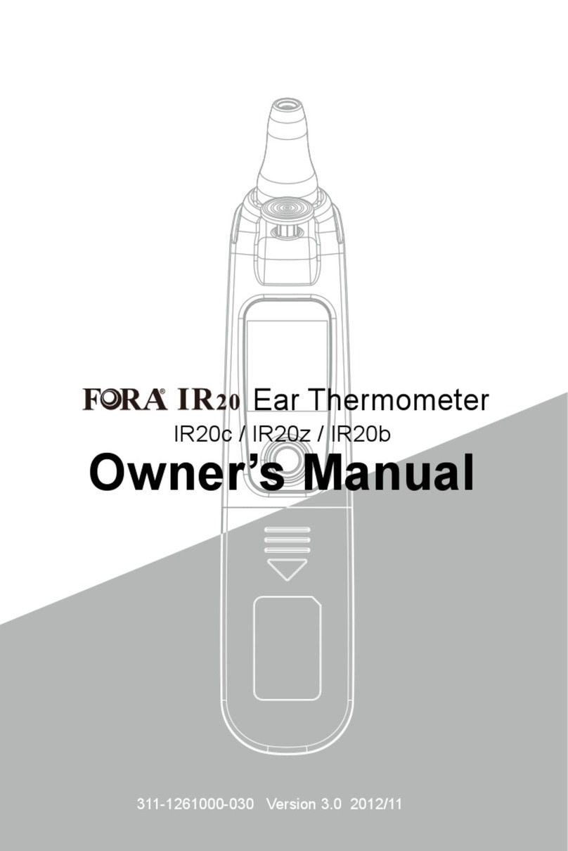
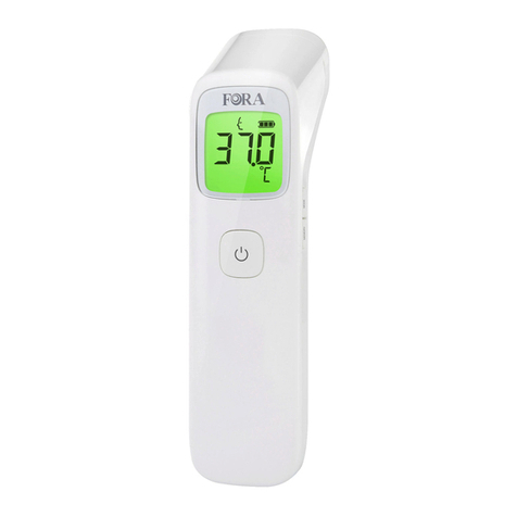
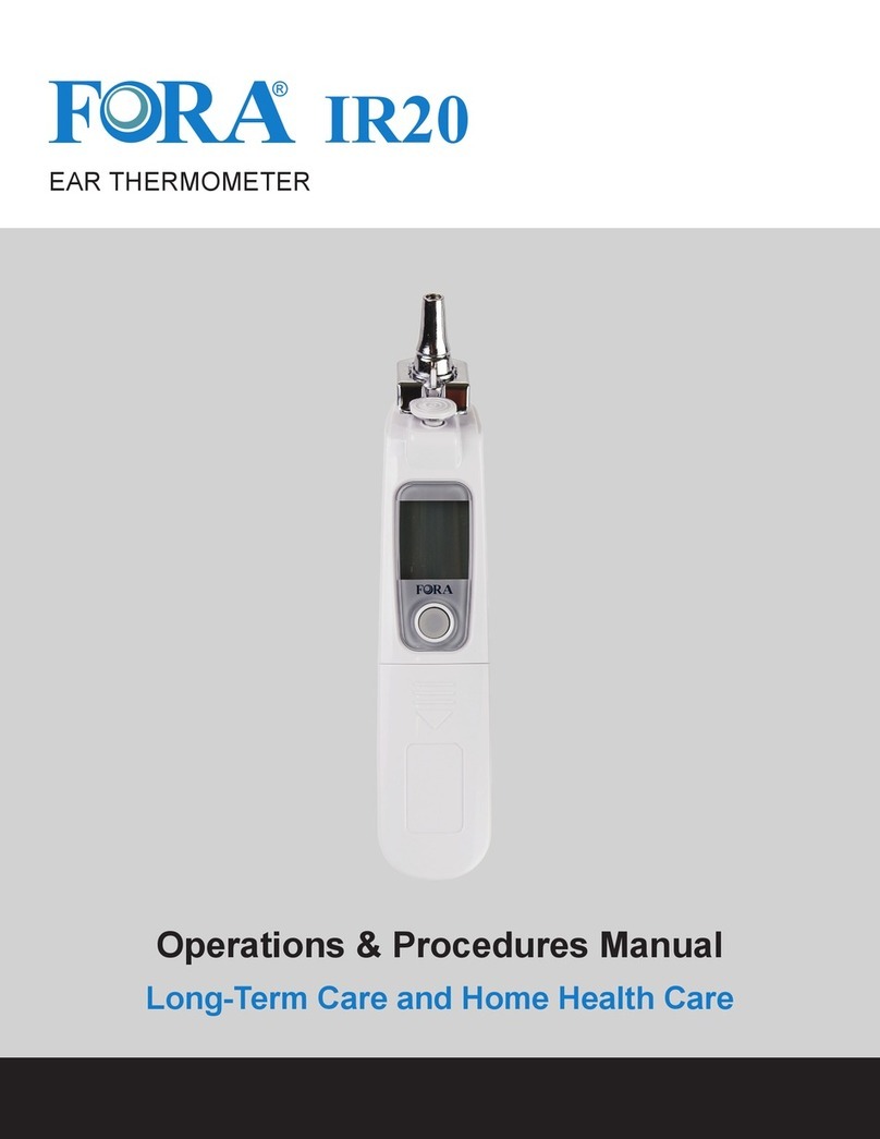
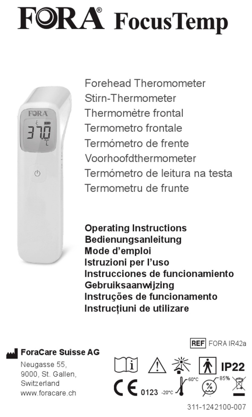
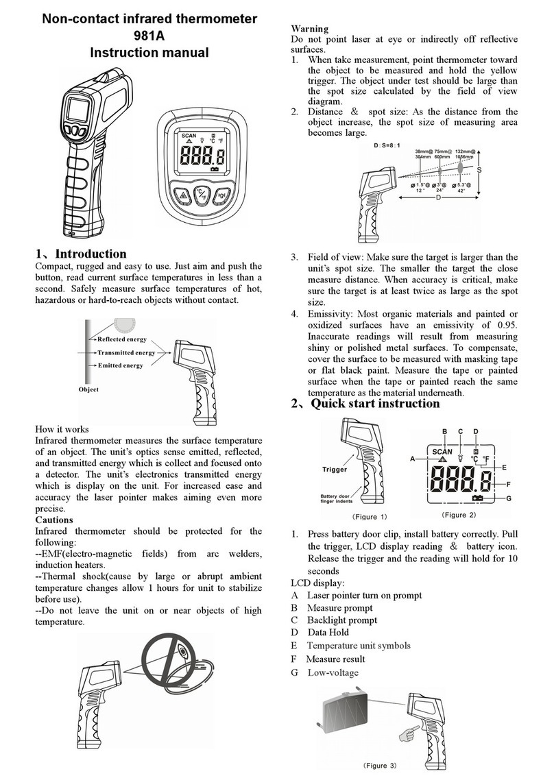
FOR-A IR20 Series User manual

Part no.
Product name
Spec
Color
Designer
311-1261000-XXX
L297*W420mm/雙面/模造紙/4折(長邊對2折+短邊對2折)完成尺寸L74*W105mm/70P/黑
機器說明書/FORA IR20b-1261C/英/FCCa/
K 100
JF

CAUTIONS AND WARNINGS
• As with any thermometer, proper technique is crucial to getting accurate
temperature readings. Please read this manual thoroughly and carefully
before use.
• Always operate the thermometer in temperatures between 16°C to 40°C
(60.8°F to 104°F) and relative humidity less than 95%.
• Always store the thermometer in a cool and dry place: temperatures between
-20°C to 60°C (-4°F to 140°F); relative humidity less than 95%. Avoid direct
sunlight.
• Avoid dropping the thermometer.
• Use only FORA IR20 probe covers for the infrared ear thermometer.
• For proper hygiene, do not share or reuse probe covers. Damaged probe
covers may result in error display.
• Do not disassemble the thermometer.
• Basic safety precautions should always be observed, especially when the
thermometer is used on or near children and disabled persons.
• This thermometer is not intended to be a substitution for a consultation with
your physician.
• Keep probe covers out of reach of children.
• Temperature measurements may differ from left to right ear. Always measure
by using the same ear.
RESTRICTIONS OF USE
This thermometer is clinically proven to produce accurate temperature
measurements. However, please be advised if you have the following
situations:
• The accuracy cannot be ensured for a person who has a deformity in their
ear, which prevents the thermometer probe from properly being inserted into
the ear canal.
• The accuracy cannot be ensured when blood or drainage is found in the ear
canal.
• If ear drops or medications have been placed in one ear, take measurements
from the other ear.
• For a person who wears an ear plug or hearing aid, remove the device and
wait for 15 minutes before taking temperature.
NOTE: Never try to clean inside your ears. You may accidentally damage the
eardrum or its surrounding tissues. Remove excess earwax only when you can
reach it with a clean cloth. Consult a physician if you suspect the presence of
excess earwax.
LCD SCREEN
311-1242000-XXX
Version 1.0 2021/06
INTRODUCTION
Thank you for choosing FORA IR20 ear thermometer. This innovative medical
device relies on advanced infrared (IR) technology to measure temperature
instantly.
INTENDED USE
FORA IR20 ear thermometer is intended for the intermittent measurement and
monitoring of human body temperature from ear canal. The device is intended
for use by people of all ages for home and professional use.
HOW DOES IT WORK
The thermometer measures the infrared heat generated by the eardrum and its
surrounding tissue. The thermometer then converts it into a temperature value
shown on the LCD screen.
APPEARANCE AND KEY FUNCTIONS OF
THE THERMOMETER
1Scan Button
Probe Lens
Probe
Probe Cover Detector
Probe Cover Ejection Button
On/Memory Button
Manufacturing Label
Battery Cover
Probe Cover
Bluetooth Indicator
2
3
4
5
6
7
8
9
10
USING THE DEVICE
MEASURING TEMPERATURES VIEWING RESULTS ON A MOBILE DEVICE
1Temperature Scanning In Progress
Temperature Reading
Memory Mode
Record Numbers
Low Battery Indicator
Temperature Unit
Communication Symbol
No Probe Cover Detected
Ear Temperature Indicator
2
3
4
5
6
7
8
9
ABOUT NORMAL BODY TEMPERATURE &
FEVER
Body temperature can vary from person to person. It also varies on different
part of the body and time of day. The following table shows the statistics of
normal ranges from different body parts. Please keep in mind that tempera-
tures measured from different parts, even at the same time, should not be
directly compared.
Fever indicates that the body temperature is higher than normal. This symptom
may be caused by infection, overdressing or immunization. Some people may
not experience fever even when they are ill. These include, but are not limited
to, infants younger than 3 months old, persons with compromised immune
systems, persons taking antibiotics, steroids or antipyretics (aspirin, ibuprofen,
acetaminophen), or persons with certain chronic illnesses. Please consult
your physician if you are concerned about your body temperature
readings.
Oral
Axillary (underarm)
Rectal
Ear
Body Site Normal Temperature Range*
35.5°C to 37.5°C (95.9°F to 99.5°F)
34.7°C to 37.3°C (94.5°F to 99.1°F)
36.6°C to 38.0°C (97.9°F to 100.4°F)
35.8°C to 38.0°C (96.4°F to 100.4°F)
IR20
EAR THERMOMETER
Operating Instructions
1
5
2
3
4
9
10
6
7
8
ForaCare Technology Canada, Inc.
2103-11871 Horseshoe Way
Richmond, B.C. V7A 5H5 Canada
Products made in Taiwan
T: (604)358-5601
(9:00 am - 6:00 pm PST, Mon.-Fri.)
www.foracarecanada.com
IMPORTANT SAFETY INSTRUCTIONS
READ THIS BEFORE USING AND KEEP THESE INSTRUCTIONS IN A
SAFE PLACE
The following basic safety precautions should always be taken.
1. Close supervision is necessary when the thermometer is used by, on, or
near children, handicapped persons or invalids.
2. Use the thermometer only for the intended use described in this manual.
3. Do not use the thermometer if it is not working properly, or if it has suffered
any damage.
4. Do not use accessories which are not supplied or recommended by the
manufacturer.
5. Proper maintenance is essential to the longevity of your device. If you are
concerned about your accuracy of measurement, please contact the local
customer service or place of purchase for help.
6
1
2
3
9 8 7
4 5
1 2
Replacing the Probe Cover
1. Check if the probe cover is clean and new. Press the infrared probe into
the cartridge.
2. Secure the cover to the probe and remove it from cartridge.
NOTE:
• If a probe cover is not attached on the probe, LCD will show “ ” until a new
probe cover is firmly attached to the probe.
• The used probe cover should be removed after each measurement to ensure
accuracy.
• To ensure proper hygiene, attach a new probe cover each time and do not
touch its tip.
1 2 31
514
1. Press and release the On/Memory button to turn on the thermometer.
When ready, the thermometer displays the last measurement.
2. Gently fit the probe with a clean probe cover into the ear canal.
3. Press and release the Scan button. You will hear a beep to indicate the
measurement is complete and the thermometer can be removed.
4. Read the result. “ ” and “ ” are shown together with a temperature
value.
5. Press the ejection button to discard the used probe cover into a trash can.
NOTE: Turn off the thermometer by pressing On/Memory button twice. It will
automatically turn off if left idle for 3 minutes.
RESULT INDICATORS
“Lo” with red backlight
Result with green backlight
Result with red backlight
“Hi” with red backlight
Temperature ≤ 31.9°C (89.5°F)
32°C (89.6°F) ≤ Temperature < 37.9°C (100.3°F)
38°C (100.4°F) ≤ Temperature < 43°C (109.4°F)
Temperature ≥ 43.1°C (109.5°F)
Status
The Bluetooth function is enabled and waiting for connection.
The Bluetooth connection is established.
Bluetooth Indicator
Flashing Blue
Solid Blue
HINTS ON TAKING TEMPERATURES
1. As with other thermometers, you may observe slight variations in consecu-
tive measurements. It is recommended that you take 3 temperature
readings and use the highest one for the following situations:
• Infants younger than 3 months old.
• Children younger than 3 years old and who have a compromised immune
system and the presence / absence of fever is critical.
• When you are learning to use the thermometer.
2. Do not take a reading while the patient is moving and/or talking. Wait for 30
minutes after any of the following situations before taking a measurement:
• When the ear has been covered.
• After exercising, swimming, or taking a bath.
• When the patient has been exposed to extreme temperature.
3. To take accurate readings, the ear must be free from excessive earwax
build-up.
RECALLING THE MEMORY
12
Your thermometer stores last 10 readings in the memory.
1. Be sure the thermometer is OFF before recalling the memory.
2. Press the On/Memory button to turn on the thermometer.
3. Press the On/Memory button for 3 seconds to enter memory mode. Each
time you press the On/Memory button, a result will be displayed in the
order of dates (latest result shown first), together with “ ” and number
(from 1 to 10). When the memory is full, the oldest result is deleted as the
new one is added. When the last record is displayed in the LCD, press
On/Memory button again to return to the first one.
4. Exit the memory. Press On/Memory button again, and then the LCD will
show “ OFF ” to exit memory.
11 133
You can transmit your data from the meter to your devices (e.g. smart phone,
tablet, PC…) via Bluetooth. Please contact your local customer service or
place of purchase for assistance. Please note that you must complete the
pairing between the meter and Bluetooth receiver before transmitting data.
Pairing with your mobile device
1. On your mobile device, turn on the Bluetooth function and follow the
pairing instructions inside of the APP (e.g., scan for the meter to add it into
APP).
2. After each measurement, the Bluetooth will be turned on automatically to
transmit data to APP.
Bluetooth indicator on the meter
WARNING:
• While the meter is in transmission mode, it will be unable to perform a test.
• Make sure your device with iOS (6 or above) or Android System (4.3 or
above) has turned on Bluetooth before transmitting the data and the meter is
within the receiving range.
REPLACING THE BATTERY
The thermometer comes with two 1.5V AAA alkaline batteries. Replace them
when “ ” appears. Please follow the steps for battery replacement.
1. Remove the battery cover.
2. Place the new batteries in the battery compartment and press it in until the
batteries are secured.
3. Reattach the battery cover.
NOTE:
• Although the thermometer works when “ ” appears, we still recommend that
you change the batteries to obtain an accurate result.
• Remove the batteries if stored for a long period of time.
• The batteries should be kept out of children. If they are swallowed, promptly
see a doctor for help.
• Properly dispose of the batteries.
132
*Chamberlain, J. M. Terndrup, T. E., New Light on Thermometer Readings,
Contemporary Pediatrics, March 1994.

TROUBLESHOOTING
MESSAGE WHAT IT MEANS WHAT TO DO
Appear when environmen-
tal temperature is below or
above system operation
range.
Put the thermometer under
operating temperature range of
16°C to 40°C (60.8°F to 104°F).
Appears when the
batteries can’t provide
enough power for a test.
Replace the old batteries with
new ones immediately.
No probe cover detected. Ensure the probe cover is fitted
on firmly, or replace it with a
new one.
Thermometer errors. Review the instructions and
re-start the measurement
procedure. If the problem
persists, please contact your
dealer.
SYMBOL INFORMATION
SPECIFICATIONS
Dimensions: 165 mm x 32.4 mm x 38.7 mm
Weight: 85.5 g
Battery: 2 x 1.5 V AAA alkaline batteries
External Output: Bluetooth
Displayed Temperature Range: 32°C to 43°C (89.6°F to 109.4°F)
Display Resolution: 0.1°C/0.1°F
Accuracy: Meet the accuracy requirement specified in ASTM E1965-98
±0.2°C (±0.4°F) for the range of 36.0°C to 39.0°C (96.8°F to 102.2°F)
±0.3°C (±0.5°F) from 32.0°C to 35.9°C (89.6°F to 96.6°F) and from 39.1°C to
43.0°C (102.4°F to 109.4°F)
Temperature Unit: °C
Operating Temperature Range: 16°C to 40°C (60.8°F to 104°F)
Operating Humidity: 95% RH or less
Storage Temperature Range: -20°C to 60°C (-4°F to 140°F)
Storage Humidity: 95% RH or less
Memory Capacity: 10 measurements
The specifications may be changed without prior notice.
CARE AND CLEANING
Electromagnetic environment-guidanceEmission test
RF emissions CISPR 11
Harmonic emissions IEC 61000-3-2
Voltage fluctuations / flicker emissions IEC 61000-3-3
Group 1
Class B
Not applicable
Not applicable
Compliance
Manufacturer’s declaration-electromagnetic emissions
The device is intended for use in the electromagnetic environment specified below.
The customer or the user of the device should assure that it is used in such an environment.
The device uses RF energy only for its internal function. Therefore, its RF
emissions are very low and are not likely to cause any interference in
nearby electronic equipment.
The device is suitable for use in all establishments, including domestic
establishments and those directly connected to the public low-voltage
power supply network that supplies buildings used for domestic purposes.
Electromagnetic environment-guidance
Electrostatic discharge
(ESD) IEC 61000-4-2
Compliance levelIEC 60601 test levelImmunity test
Manufacturer’s declaration-electromagnetic immunity
The device is intended for use in the electromagnetic environment specified below.
The customer or the user of the device should assure that it is used in such an environment.
Floors should be wood, concrete or ceramic tile. If floors are
covered with synthetic material, the relative humidity should be at
least 30 %.
Mains power quality should be that of a typical home and
professional healthcare environment.
Mains power quality should be that of a typical home and
professional healthcare environment.
The device power frequency magnetic fields should be at levels
characteristic of a typical location in a typical home and
professional healthcare environment.
Mains power quality should be that of a typical home and
professional healthcare environment. If the user of the device
requires continued operation during power mains interruptions, it is
recommended that the device be powered from an uninterruptible
power supply or a battery.
Electrical fast transient
/ burst IEC 61000-4-4
Surge IEC 61000-4-5
Power frequency (50,
60 Hz) magnetic field
IEC 61000-4-8 U
Voltage Dips, short
interruptions and
voltage variations on
power supply input
lines IEC 61000-4-11
Contact: ±8 kV
Air ±2 kV, ±4 kV, ±8 kV,
±15 kV
Not applicable
Not applicable
Not applicable
Not applicable
30 A/m
50 Hz and 60 Hz
Voltage dips:
Not applicable
Not applicable
Not applicable
Voltage interruptions:
Not applicable
Contact: ±8 kV
Air ±2 kV, ±4 kV, ±8 kV, ±15 kV
±2 kV for power supply lines
±1 kV for input/output lines
±0.5 kV, ±1 kV line(s) to line(s)
±0.5 kV, ±1 kV, ±2 kV line(s) to
earth
30 A/m
50 Hz or 60 Hz
Voltage dips:
0 % UT; 0,5 cycle
0 % UT; 1 cycle
70 % UT; 25/30 cycles
Voltage interruptions:
0 % UT; 250/300 cycle
NOTE UT is the a.c. mains voltage prior to application of the test level.
Separation distance according to frequency of transmitter
(m)
0,01
0,1
1
10
100
N/A
N/A
N/A
N/A
N/A
0,12
0,38
1,2
3,8
12
0,23
0,73
2,3
7,3
23
Rated maximum output power of
transmitter
(W) 150 kHz to 80 MHz
d =1,2√P
80 MHz to 800 MHz
d =1,2√P
800 MHz to 2,7 GHz
d =2,3√P
Recommended separation distance between
portable and mobile RF communications equipment and the device
The device is intended for use in an electromagnetic environment in which radiated RF disturbances are controlled. The customer or the user of the device
can help prevent electromagnetic interference by maintaining a minimum distance between portable and mobile RF communications equipment
(transmitters) and the device as recommended below, according to the maximum output power of the communications equipment.
For transmitters rated at a maximum output power not listed above, the recommended separation distance d in meters (m) can be estimated using the
equation applicable to the frequency of the transmitter, where p is the maximum output power rating of the transmitter in watts (W) according to the
transmitter manufacturer.
NOTE1 At 80 MHz and 800 MHz, the separation distance for the higher frequency range applies.
NOTE2 These guidelines may not apply in all situations. Electromagnetic propagation is affected by absorption and reflection from structures, objects and
people.
385 380 – 390 TETRA 400
Pulse
modulation b)
18 Hz
1,8 0,3 27 27
710
745
780
704 – 787 LTE Band 13,
17
Pulse
modulation b)
217 Hz
0,2 0,3 9 9
5240
5500
5785
5100 –
5800
WLAN 802.11
a/n
Pulse
modulation b)
217 Hz
0,2 0,3 9 9
810
870
930
800 – 960
GSM 800/900,
TETRA 800,
iDEN 820,
CDMA 850,
LTE Band 5
Pulse
modulation b)
18 Hz
2 0,3 28 28
2450 2400 –
2570
Bluetooth,
WLAN,
802.11 b/g/n,
RFID 2450,
LTE Band 7
Pulse
modulation b)
217 Hz 2 0,3 28 28
1720
1845
1970
1700 –
1990
GSM 1800;
CDMA 1900;
GSM 1900;
DECT;
LTE Band 1, 3,
4, 25; UMTS
Pulse
modulation b)
217 Hz
2 0,3 28 28
450 430 – 470 GMRS 460,
FRS 460
FM c)
±5 kHz deviation
1 kHz sine
2 0,3 28 28
Test
frequency
(MHz)
Maximum
power
(W)
Distance
(m)
IMMUNITY
TEST LEVEL
(V/m)
Compliance LEVEL
(V/m)
Band a)
(MHz)
Service a) Modulation b)
Manufacturer’s declaration-electromagnetic immunity
Test specifications for ENCLOSURE PORT IMMUNITY to RF wireless communications equipment
The device is intended for use in the electromagnetic environment specified below.
The customer or the user of the device should assure that it is used in such an environment.
NOTE If necessary to achieve the IMMUNITY TEST LEVEL, the distance between the transmitting antenna and the ME EQUIPMENT or ME SYSTEM may
be reduced to 1 m. The 1 m test distance is permitted by IEC 61000-4-3.
a) For some services, only the uplink frequencies are included.
b) The carrier shall be modulated using a 50 % duty cycle square wave signal.
c) As an alternative to FM modulation, 50 % pulse modulation at 18 Hz may be used because while it does not represent actual modulation, it would be
worst case.
Electromagnetic environment-guidance
Conducted RF
IEC 61000-4-6
Radiated RF
IEC 61000-4-3
Compliance levelIEC 60601 test levelImmunity test
Manufacturer’s declaration-electromagnetic immunity
The device is intended for use in the electromagnetic environment specified below.
The customer or the user of the device should assure that it is used in such and environment.
Portable and mobile RF communications equipment should be
used no closer to any part of the device including cables, than the
recommended separation distance calculated from the equation
applicable to the frequency of the transmitter.
Recommended separation distance:
d = 1,2 √P
d = 1,2 √P 80MHz to 800 MHz
d = 2,3 √P 800MHz to 2,7 GHz
Where P is the maximum output power rating of the transmitter in
watts (W) according to the transmitter manufacturer and d is the
recommended separation distance in metres (m).
Interference may occur in the vicinity of equipment marked with the
following symbol:
Not applicable
Not applicable
10 V/m
80 MHz – 2,7 GHz
80 % AM at 1 kHz
3 Vrms:
0,15 MHz – 80 MHz
6 Vrms:
in ISM and amateur
radio bands between
0,15 MHz and 80 MHz
80 % AM at 1 kHz
10 V/m
80 MHz – 2,7 GHz
80 % AM at 1 kHz
NOTE1 At 80 MHz and 800 MHz, the higher frequency range applies.
NOTE2 These guidelines may not apply in all situations. Electromagnetic propagation is affected by absorption and reflection from structures, objects and
people.
a Field strengths from fixed transmitters, such as base stations for radio (cellular / cordless) telephones and land mobile radios, amateur radio, AM and FM
radio broadcast and TV broadcast cannot be predicted theoretically with accuracy. To assess the electromagnetic environment due to fixed RF
transmitters, an electromagnetic site survey should be considered. If the measured field strength in the location in which the device is used exceeds the
applicable RF compliance level above, the device should be observed to verify normal operation. If abnormal performance is observed, additional
measures may be necessary, such as re-orienting or relocating the device.
b Over the frequency range 150 kHz to 80 MHz, field strengths should be less than 3 V/m.
• The probe is not waterproof. Please wipe it with a clean and dry cotton swab.
• The body of the thermometer is not water-resistant. Never put the thermome-
ter under a running tap or submerge it into water. Use a soft and dry cloth to
clean it. Do not use abrasive cleaners.
• Store the thermometer in a cool and dry location. Free from dust and away
from direct sunlight.
Symbol Referent
Consult instructions for use
This device does not belong to household waste and must be
returned to a collection point for recycling electric and electronic
devices according to local laws. If it contains batteries, the
batteries should be removed and disposed in accordance with local
regulations for separate collection of spent batteries.
Manufacturer
Serial number
Caution
Do not re-use (Probe cover use only)
Symbol Referent
Type BF applied part
Temperature limit
Humidity limitation
RoHS Compliance
Other manuals for IR20 Series
5
Other FOR-A Thermometer manuals

FOR-A
FOR-A IR20 Series User manual

FOR-A
FOR-A IR18 User manual

FOR-A
FOR-A MT Series User manual

FOR-A
FOR-A IR10 User manual

FOR-A
FOR-A FocusTemp User manual

FOR-A
FOR-A IR20 Series User manual

FOR-A
FOR-A IR21 User manual

FOR-A
FOR-A FocusTemp IR42a User manual

FOR-A
FOR-A IR20b User manual

FOR-A
FOR-A TM10 User manual