manuals.online logo
Brands
  1. Home
  2. •
  3. Brands
  4. •
  5. Fracarro
  6. •
  7. Switch
  8. •
  9. Fracarro MULTISWITCH SWI504SA User manual

Fracarro MULTISWITCH SWI504SA User manual

I: MULTISWITCH IN CASCATA CON SEGNALE TV PASSIVO
E REGOLAZIONE DEL GUADAGNO SAT.
GB: CASCADABLE MULTISWITCH WITH PASSIVE TV SIGNAL
AND SAT GAIN REGULATION.
F: MULTISWITCH EN CASCADE AVEC SIGNAL TV PASSIF
ET RÉGLAGE DU GAIN SAT.
D: PASSIVE MULTISCHALTER-KASKADE FÜR TV-SIGNAL
UND REGULIERUNG DER SAT VERSTÄRKUNG
MULTISWITCH SWI504SA - SWI506SA- SWI508SA
ISTRUZIONI PER L’USO
OPERATING INSTRUCTIONS
INSTRUCTIONS D’EMPLOI
BETRIEBSANLEITUNG
2
I: AVVERTENZE PER LA SICUREZZA
L’installazione del prodotto deve essere eseguita da personale
qualificato in conformità alle leggi e normative locali sulla
sicurezza. Fracarro Radioindustrie di conseguenza è esonerata da
qualsivoglia responsabilità civile o penale conseguente a violazioni
delle norme giuridiche vigenti in materia e derivanti dall’improprio
uso del prodotto da parte dell’installatore, dell’utilizzatore o di
terzi. L’installazione del prodotto deve essere eseguita secondo le
indicazioni di installazione fornite, al fine di preservare l’operatore
da eventuali incidenti e il prodotto da eventuali danneggiamenti.
Avvertenze per l’installazione
฀Umidità e gocce di condensa potrebbero danneggiare il
prodotto. In caso di condensa, prima di utilizzare il prodotto,
attendere che sia completamente asciutto.
฀Maneggiare con cura. Urti impropri potrebbero danneggiare
il prodotto.
฀Lasciare spazio attorno al prodotto per garantire una
ventilazione sufficiente.
฀L’eccessiva temperatura di lavoro e/o un eccessivo
riscaldamento possono compromettere il funzionamento e la
durata del prodotto.
฀Non installare il prodotto sopra o vicino a fonti di calore o
in luoghi polverosi o dove potrebbe venire a contatto con
sostanze corrosive.
฀In caso di montaggio a muro utilizzare tasselli ad
espansioneadeguati allle caratteristiche del supporto di
fissaggio.
฀Il prodotto non deve essere esposto a gocciolamento o
a spruzzi d’acqua e va pertanto installato in un ambiente
asciutto, all’interno di edifici.
฀Il prodotto deve essere collegato all’elettrodo di terra
dell’impianto d’antenna conformemente alla norma
EN6072811. La vite predisposta a tale scopo è
contrassegnata con il simbolo .
Si raccomanda di attenersi alle disposizioni della norma
EN6072811 e di non collegare tale vite alla terra di protezione
della rete elettrica di alimentazione.
Avvertenze generali
In caso di guasto non tentate di riparare il prodotto altrimenti la
garanzia non sarà più valida. Fracarro Radioindustrie SpA dichiara
che il prodotto è conforme alla seguente norma armonizzata:
CEI EN 500832 ed è quindi conforme ai requisiti essenziali della
seguente direttiva (comprese tutte le modifiche applicabili):
2004/108/EC, Direttiva Compatibilità Elettromagnetica (EMC).
Le informazioni riportate in questo manuale sono state compilate
con cura, tuttavia Fracarro Radioindustrie S.p.A. si riserva il diritto
di apportare in ogni momento e senza preavviso, miglioramenti
e/o modifiche ai prodotti descritti nel presente manuale.
Consultare il sito www.fracarro.it per le condizioni di assistenza
e garanzia.
GB: SAFETY WARNINGS
The product can only be installed by qualified personnel in
compliance with local safety laws and regulations. Fracarro
Radioindustrie is free from all civil and criminal responsibility due
to breaches of the current legislation derived from the improper
use of the product by the installer, user or third parties. The
product must be used in full compliance with the instructions
given in this manual, in order to protect the operator against all
possible injury and the product from being damaged.
Installation warnings
฀Damp and condensation drops could damage the product,
and consequently always wait for the product to be perfectly
dry before use.
฀Handle with care. Knocks could damage the product.
฀Leave plenty of space around the product to ensure sufficient
ventilation.
฀High temperatures or overheating could compromise the
product functions and life.
฀Do not install the product above or close to sources of heat, in
dusty atmospheres or when it could be exposed to corrosive
substances.
฀If you wall-mount the product, use expansion anchors that are
suitable for the characteristics of the support bracket.
฀The product must not be exposed to water drips and must be
installed on the inside in dry atmospheres.
฀The product must be connected to the antenna line earth
plate, in compliance with the EN60728-11 standard.
The earth screw is indicated with the symbol .
It is important to observe the dispositions of the EN60728-11
standard and not connect this screw (terminal) (product) to the
power supply earth line.
General warnings
In case of a malfunction, do not attempt to repair the product
because this would invalidate the guarantee.
Fracarro Radioindustrie SpA declares that the product is in
compliance with the following harmonised standard:
CEI EN 50083-2 and therefore conforms to the essential
requirements of the following directives (including all applicable
amendments: 2004/108/EC, Electromagnetic Compatibility
Directive (EMC)
The information in this manual has been compiled with care;
nevertheless, Fracarro Radioindustrie S.p.A. reserves the right to
make improvements and / or changes to the products described
in this manual at any time and without notice. You can find our
support and warranty terms on www.fracarro.com.
3
F: AVERTISSEMENT DE SECURITE
Le produit doit être installé par du personnel qualifié,
conformément aux lois et réglementations locales en matière de
sécurité. Fracarro Radioindustrie est par conséquent déchargée
de toute responsabilité civile ou pénale conséquente à des
violations des normes juridiques en vigueur en la matière et
dérivant de l’usage incorrect du produit de la part de l’installateur,
de l’utilisateur ou de tiers.
Le produit doit être installé en suivant les indications fournies,
afin de préserver l’opérateur d’éventuels accidents et le produit
d’éventuels endommagements.
Avertissements d’installation
฀L’humidité et les gouttes de condensation pourraient
endommager le produit. En cas de condensation, attendre
que le produit soit complètement sec avant de l’utiliser.
฀Manier avec soin. Les chocs pourraient endommager le
produit.
฀Laisser assez de place autour du produit, afin de garantir une
aération suffisante.
฀La température excessive de fonctionnement et/ou un
réchauffement excessif peuvent nuire au fonctionnement et à
la durée du produit.
฀Ne pas installer le produit sur ou à proximité de sources
de chaleur ou dans des endroits poussiéreux ou bien dans
des endroits où ils pourraient entrer en contact avec des
substances corrosives.
฀En cas de montage mural, utiliser des chevilles à expansion
correspondant aux caractéristiques du support de fixation.
฀Le produit ne doit pas être exposé à l’égouttement ou à des
jets d’eau ; il doit donc être installé dans un environnement
sec, à l’intérieur de bâtiments.
฀Le produit doit être relié à l’électrode de terre de l’antenne
conformément à la norme EN6072811.
La vis prévue à cet effet est caractérisée par le symbol .
Il est conseillé de respecter les dispositions de la norme
EN60728-11 et de ne pas relier cette vis à la terre de
protection du secteur.
Avertissements généraux
En cas de panne, ne pas tenter de réparer le produit, sans quoi la
garantie ne sera plus valable. Fracarro Radioindustrie SpA déclare
que le produit est conforme à la norme harmonisée CEI EN 50083-
2 et est donc conforme aux conditions essentielles des directives
suivantes (y compris toutes les modifications applicables):
2004/108/EC, Directive Compatibilité Électromagnétique (EMC)
Les informations indiquées dans ce mode d’emploi ont été
renseignées soigneusement ; toutefois, Fracarro Radioindustrie
S.p.A. se réserve le droit d’améliorer et/ou de modifier à tout
moment et sans préavis les produits décrits dans ce mode
d’emploi. Consulter le site www.fracarro.fr pour connaître les
conditions d’assistance et de garantie.
D: SCHUTZMASSNAHMEN
Die Installation vom Produkt muss von qualifiziertem Fachpersonal
unter Beachtung der maßgeblichen Bestimmungen und der
geltenden Sicherheitsvorschriften durchgeführt werden. Bei
Verstoß gegen die maßgeblichen gesetzlichen Bestimmungen
und bei unsachgemäßem Gebrauch des Produkts durch
den Installateur, den Benutzer oder Dritte ist die Fa. Fracarro
Radioindustrie ist von jeder zivil- und strafrechtlichen Haftung
enthoben. Die Installation des Produkts muss unter Beachtung der
mitgelieferten Installationsanleitung erfolgen, um den Bediener vor
eventuellen Unfällen und das Produkt vor eventuellen Schäden zu
schützen.
Installationshinweise
฀Feuchtigkeit und Kondenswasser können das Produkt
schädigen. Wenn Kondensat festgestellt wird, muss das
vollständige Trocknen vom Produkt abgewartet werden, bevor
es benützt wird.
฀Das Produkt mit der gebotenen Vorsicht handhaben. Stöße
und Schläge können zu Schäden am Produkt führen.
฀Um das Produkt herum ausreichend Freiraum lassen, um eine
ausreichende Belüftung zu gewährleisten.
฀LEine zu hohe Betriebstemperatur u/o ein übermäßiges
Erhitzen können die Funktionstüchtigkeit und die
Nutzungsdauer des Produktes beeinträchtigen.
฀Das Produkt nicht auf oder in der Nähe von Wärmequellen
oder an staubigen Orten oder an Orten installieren, an denen
das Produkt mit korrosiven Substanzen in Berührung kommen
kann.
฀Bei Wandmontage müssen Dübel verwendet werden, die sich
für die Wand eignen, an der das Produkt montiert wird.
฀Das Produkt muss vor Tropfwasser und Spritzwasser
geschützt werden und muss deshalb an einem trockenen Ort
in einem Gebäude installiert werden.
฀Das Produkt muss an die Erdungsklemme der
Antennenanlage nach Vorgabe der Norm EN6072811
angeschlossen werden. Die dafür vorgesehene Schraube ist
mit dem entsprechenden Symbol gekennzeichnet .
Es wird ausdrücklich darauf hingewiesen, dass die Vorgabe
der Norm EN6072811 beachtet werden müssen und die
Schraube NICHT an die Schutzerde der Stromleitung
angeschlossen werden darf.
Allgemeine Hinweise
Versuchen Sie nicht, das Produkt bei Defekt selbst zu reparieren,
sonst verfällt die Garantie. Fracarro Radioindustrie SpA
erklärt, dass das Produkt mit folgender harmonisierter Norm
konform ist: DIN EN 50083-2 und damit den wesentlichen
Sicherheitsanforderungen folgender Richtlinie (einschließlich aller
maßgeblichen Änderungen) entspricht: EMV-Richtlinie 2004/108/
EG zur Elektromagnetischen Verträglichkeit.
Die im vorliegenden Handbuch enthaltenen Informationen wurden
sorgfältig erstellt. Die Fa. Fracarro Radioindustrie S.p.A. behält
sich dennoch das Recht vor, jederzeit und ohne Vorankündigung
-Verbesserungen u/o Änderungen an den im vorliegenden
Handbuch beschriebenen Produkten durchzuführen. Nähere
Informationen zu den Kundendienst- und Garantiebedingungen
finden Sie auf der Webseite www.fracarro.com/de.
4
I: DESCRIZIONE DEL PRODOTTO
GB:PRODUCT DESCRIPTION
F: DESCRIPTION DU PRODUIT
D: PRODUKTBESCHREIBUNG
I: Vite di messa a terra
GB: Grounding screw
F: Vis de mise à la terre
D: Erdungsschraube
I: Alimentazione dell’LNB
attraverso le linee passanti.
GB: Supply of LNB through
trunk lines.
F: Fourniture de LNB à
travers les lignes de jonction.
D: Versorgung mit LNB durch
Fernleitungen.
Fig.2
I: Multiswitch in cascata della serie SWI50xSA con 5
ingressi per distribuire una posizione satellitare fino a
4, 6 e 8 prese utente. L’alimentazione del multiswitch
viene ricevuta interamente attraverso le derivate
utente e viene segnalata dal LED verde, mentre
l’alimentazione dell’LNB deve essere effettuata
mediante un alimentatore esterno (Fig.2). Il segnale
SAT può essere regolato attraverso il trimmer
posto sul lato destro della meccanica; portando il
trimmer a fondo scala si hanno i guadagni minimi
indicati nelle specifiche. Attraverso la montante TV
è possibile alimentare un eventuale amplificatore di
testa, il LED giallo segnala la presenza della tensione
su questa linea.
Il multiswitch viene alimentato tramite decoder;
mentre l’LNB deve essere alimentato con un
alimentatore esterno, posto in testa o a valle
dell’impianto; quest’ultimo può essere connesso ad
una qualsiasi delle 4 porte satellite.
GB: Cascadable multiswitches in the SWI50xSA
series, with 5 inputs to distribute a satellite position
to 4, 6 and 8 user sockets. The Multiswitch power
is entirely received through the user’s circuit and is
shown by the green LED, while the LNB power must
be powered by an external power pack (Fig. 2). The
SAT signal can be regulated by the trimmer on the
right side of the case, by taking the trimmer to the
bottom scale the minimum gains are given indicated
in the specifications. Using the TV busbar, a head
amplifier can be powered and the yellow LED shows
when this line is powered.
The multiswitch is powered by a decoder, but the
LNB must be powered by an external power pack
situated on the head or downstream from the
installation, which must be connected to any one of
the 4 satellite ports.
F: Multiswitch en cascade de la série SWI50xSA
à 5 entrées pour distribuer une position satellite
jusqu’à 4, 6 et 8 prises utilisateur. L’alimentation du
multiswitch est entièrement reçue par des dérivées
utilisateur et elle est indiquée par la LED verte,
tandis que LNB est alimenté par une alimentation
externe (Fig.2). Le signal SAT peut être réglé par un
trimmer présent sur le côté droit du boîtier. Lorsque
le trimmer est en fond d’échelle, les gains minimums
indiqués dans les caractéristiques techniques sont
obtenus. Au moyen du signal montant TV, il est
possible d’alimenter un éventuel amplificateur de
tête, la LED jaune signale la présence de la tension
sur cette ligne.
Le multiswitch est alimenté par le décodeur ; tandis
que LNB est alimenté par une alimentation externe
en amont ou en aval de l’unité et branché à n’importe
lequel des 4 ports satellite.
D: Multischalter-Kaskade der Serie SWI50xSA mit
5 Eingängen für die Verteilung eines SAT-Signals
an 4, 6 und 8 Abnehmer. Die Stromversorgung vom
Multischalter erfolgt über die Abnehmer und wird
von der grünen LED angezeigt. Die Stromversorgung
vom LNB erfolgt über ein externes Netzgerät (Abb.
2). Das Satellitensignal kann mit dem Trimmer an
der rechten Seite vom Schalter reguliert werden.
Wenn der Trimmer bis zum Anschlag gedreht wird,
erhält man die in den Spezifikationen angegebene
Mindestverstärkung. Über die TV Steigleitung kann
ein eventueller Kopfverstärker mit Strom versorgt
werden. Die gelbe LED zeigt an, wenn Spannung
auf dieser Leitung anliegt.
Der Multischalter wird über den Decoder mit Strom
versorgt. Das LNB muss von einem externen
Netzgerät gespeist werden, das vor oder nach der
Anlage installiert werden muss. Das Netzgerät kann
an einen beliebigen der 4 SAT-Ports angeschlossen
werden.
Fig.1
5
I: INSTALLAZIONE DEL PRODOTTO
GB:PRODUCT INSTALLATION
F: PRODUCT INSTALLATION
D: INSTALLATION DES ERZEUGNISSES
I: Per un corretto funzionamento il multiswitch deve
essere alimentato tramite decoder. L’LNB deve
essere alimentato con un alimentatore esterno
posto in testa o a valle dell’impianto, quest’ultimo
può essere connesso ad una qualsiasi delle 4
porte satellite: Verticale Basso (Nero), Orizzontale
basso (Verde), Verticale Alto (Rosso) o Orizzontale
Alto (Giallo). Facile integrazione con impianti già
esistenti grazie alla sua ridotta perdita di passaggio
TV e satellite. Possibilità di alimentare un eventuale
amplificatore attraverso la montante TV (max 1A a
12V/24V es. serieMAPxxx, MAKxxxx).
L’installazione del prodotto deve essere eseguita
esclusivamente utilizzando gli appositi supporti di
plastica.
GB: To work correctly the multiswitch is powered
by a decoder, but the LNB must be powered by
an external power pack situated on the head or
downstream from the installation, which must
be connected to any one of the 4 satellite ports:
Vertical Low (Black), Horizontal Low (Green), Vertical
High (Red) or Horizontal High (Yellow). It is easy to
incorporate into pre-existing systems thanks to the
reduced TV and satellite passage loss. An amplifier
can also be powered through the TV busbar (max.
1A at 12V/24V e.g. MAPxxx, MAKxxxx series).
The products must only be installed using the
special plastic supports.
F: Pour un fonctionnement correct, le multiswitch
doit être alimenté par le décodeur. LNB doit être
alimenté par une alimentation externe en amont ou
en aval de l’unité depuis n’importe quel port satellite
: Vertical Bas (Noir), Horizontal bas (Vert), Vertical
Haut (Rouge) ou Horizontal Haut (Jaune). Intégration
facile avec les installations déjà existantes grâce à la
perte réduite de passage TV et satellite. Possibilité
d’alimenter un amplificateur éventuel au moyen
du signal montant TV (max 1A à 12V/24V ex. série
MAPxxx, MAKxxxx).
L’installation du produit ne doit être exécutée qu’en
utilisant les supports en plastique prévus à cet effet.
le trimmer est en fond d’échelle, les gains minimums
indiqués dans les caractéristiques techniques sont
obtenus. Au moyen du signal montant TV, il est
possible d’alimenter un éventuel amplificateur de
tête, la LED jaune signale la présence de la tension
sur cette ligne.
Le multiswitch est alimenté par le décodeur ; tandis
que LNB est alimenté par une alimentation externe
en amont ou en aval de l’unité et branché à n’importe
lequel des 4 ports satellite.
D: Damit der Multischalter korrekt funktioniert, muss
er über den Decoder mit Strom versorgt werden.
Das LNB muss von einem externen Netzgerät
gespeist werden, das vor oder nach der Anlage
installiert werden muss. Das Netzgerät kann an
einen beliebigen der 4 SAT-Ports angeschlossen
werden: vertikal unten (schwarz), horizontal unten
(grün), vertikal oben (rot) oder horizontal oben (gelb).
Der Multischalter lässt wich wegen seinem geringen
TV- und SAT-Signalverlust problemlos in vorhandene
Anlagen einbauen. Über die TV Steigleitung kann
ein eventueller Kopfverstärker mit Strom versorgt
werden (max. 1A bei 12V/24V, z.B. Serie MAPxxx
oder MAKxxxx).
Das Produkt muss mit den dafür vorgesehenen
Kunststoffhalterungen installiert werden.
6
I: Schema Impianto 3 piani 8 prese per piano
GB: Plant layout 3 floors 8 outlets per floor
F: Schéma d’installation 3 étages 8 prises par étage
D: Anlagenplanung 3 Etagen 8 Steckdosen pro Etage
I: ESEMPI DI CONFIGURAZIONE
GB: CONFIGURATION EXAMPLES
F: EXEMPLE DE CONFIGURATION
D: KONFIGURATIONSBEISPIEL
7
I: Schema Impianto 6 piani 6 prese per piano senza amplificatore di rilancio
GB: Plant layout 6 floors 6 outlets per floor without launch amplifier
F: Schéma d’installation 6 étages 6 prises par étage lancement sans amplificateur
D: Anlagenplanung 6 Etagen 6 Steckdosen pro Etage Start ohne Verstärker
I: ESEMPI DI CONFIGURAZIONE
GB: CONFIGURATION EXAMPLES
F: EXEMPLE DE CONFIGURATION
D: KONFIGURATIONSBEISPIEL
8
I: Schema Impianto 4 piani interamente alimentato dallo SWI4508DT
GB: Plant layout 4 floors entirely fed by SWI4508DT
F: Schéma d’installation 4 étages entièrement alimenté par SWI4508DT
D: Anlagenplanung 4 Etagen vollständig von SWI4508DT zugeführt
I: ESEMPI DI CONFIGURAZIONE
GB: CONFIGURATION EXAMPLES
F: EXEMPLE DE CONFIGURATION
D: KONFIGURATIONSBEISPIEL
9
I: ISTRUZIONI PER L’UTILIZZO
GB: USER’S INSTRUCTIONS
F: INSTRUCTIONS POUR L’UTILISATION
D: BETRIEBSANLEITUNG
I: Non utilizzare Derivatori perché non permettono
il passaggio dei toni di comando dal decoder al
Multiswitch; per un corretto funzionamento del
sistema il collegamento tra la presa e il multiswitch
deve essere diretto, in caso contrario il prodotto
potrebbe non funzionare.
GB:Do not use shunts because they do not allow
passing the command tones from the decoder to
the Multiswitch. To work correctly, the connection
system must be direct between the socket and the
Multiswitch, otherwise it may not work.
F:Ne pas utiliser de dérivateurs étant donné qu’ils
ne permettent pas le passage des tonalités de
commande du décodeur au Multiswitch. Pour un
fonctionnement correct du système, le branchement
entre la prise et le multiswitch doit être direct, sans
quoi le produit pourrait ne pas fonctionner.
D:Es dürfen KEINE Abzweiger verwendet werden,
da sie die Steuersignale vom Decoder nicht zum
Multischalter durchlassen. Damit das System
korrekt funktioniert, muss der Multischalter direkt an
die Buchse angeschlossen werden, da das Produkt
sonst möglicherweise nicht funktioniert.
IN OUT
SWI504SA
SWI506SA
SWI508SA
104 dBµV 90 dBµV
I: Per 30 canali sat
GB: For 30 SAT channels
F: Pour 30 canaux sat
D: Für 30 SAT-Kanäle
RX
14V 1
18V 2
14V + 22kHz 3
18V + 22kHz 4
I: Commutazioni
GB: Switches
F: Commutations
D: Umschaltungen
10
I: Funzione dei Led e Regolazione SAT:
1) POWER ON: LED VERDE. Se il multiswitch viene
opportunamente alimentato il LED sarà acceso; in
caso di cortocircuito sulle linee di alimentazione
SAT il LED sarà invece spento; in questo caso
disconnettere l’alimentazione, rimuovere il corto
circuito e riconnettere l’alimentazione; il LED sarà
nuovamente acceso.
2) POWER TV: LED GIALLO. Se acceso, segnala il
corretto passaggio della tensione sulla montante TV;
se spento segnala invece la presenza di un corto
circuito.
3) TRIMMER REGOLAZIONE DEL GUADAGNO SAT.
GB: Led functions and SAT regulation:
1) POWER ON: GREEN LED: If the Multiswitch is
correctly powered the LED is on; if there is a short
circuit on the SAT power lines, the LED is off. In this
case, disconnect power, eliminate the short-circuit
and reconnect power and the LED is back on.
2) TV POWER: YELLOW LED: ON shows the correct
passage of voltage on the TV busbar, OFF means
there is a short-circuit.
3) SAT GAIN ADJUSTMENT.
F: Fonction des LED et Réglage SAT :
1) POWER ON : LED VERTE. Lorsque le multiswitch
est alimenté correctement, la LED sera allumée ;
en cas de court-circuit sur les lignes d’alimentation
SAT, la LED est éteinte : dans ce cas débrancher
l’alimentation, éliminer le court-circuit et rebrancher
l’alimentation ; la LED s’allume de nouveau.
2) POWER TV : LED JAUNE. Si elle est allumée,
elle indique le passage correct de la tension sur le
signal montant TV ; si elle est éteinte, elle indique en
revanche un court-circuit.
3) RÉGLAGE DE GAIN SAT.
D: Funktion der LEDs und Regulierung SAT:
1) POWER ON: GRÜNE LED. Wenn der Multischalter
korrekt mit Strom versorgt wird, schaltet sich die LED
ein. Bei Kurzschluss an den Stromleitungen der SAT-
Anlage ist die LED ausgeschaltet. In diesem Fall die
Stromversorgung trennen, den Kurzschluss beheben
und die Stromversorgung wieder einschalten. Die
LED schaltet sich wieder ein.
2) POWER TV: GELBE LED. Das Einschalten der
LED zeigt den korrekten Stromdurchgang an der
TV Steigleitung an. Bei Kurzschluss ist die LED
ausgeschaltet.
3) SAT VERSTÄRKUNGSEINSTELLUNG.
POWER ON
SAT GAIN ADJUSTMENT
POWER TV
I: Funzione dei Led e Regolazione SAT
GB: Led functions and SAT regulation
F: Fonction des LED et Réglage SAT
D: Funktion der LEDs und Regulierung SAT
11
I: SPECIFICHE TECNICHE
GB: TECHNICAL SPECIFICATIONS
F: SPECIFICATIONS TECHNIQUES
D: TECHNISCHE SPEZIFIKATIONEN
SWI504SA SWI506SA SWI508SA
I: Numero uscite
GB: Output number
F: Nombre de sorties
D: Anzahl Ausgänge
N° 4 6 8
I: Numero d’ingressi
GB: Input number
F: Nombre d’entrées
D: Anzahl Eingänge
N° 5 (4 SAT + 1TV)
I: Larghezza di Banda TERR.
GB: Terrestrial bandwidth
F: Largueur de bande TERR.
D: Bandbreite TERR.
MHz 88-790
I: Perdita in derivata TERR.
GB: Terrestrial derivative loss
F: Perte de dérivée TERR
D: Abzweigungsverlust TERR.
dB -26 -27 -28
I: Perdita di pasaggio TERR.
GB: Terrestrial passage loss
F: Perte de passage TERR.
D: Durchgangsverlust TERR.
dB 1,5
I:Return loss ingresso TV
GB: TV input return loss
F: Return loss entrée TV
'5FNÀXVVGlPSIXQJ(LQJDQJ79
dB >15
I: Larghezza di Banda SAT
GB: SAT bandwidth
F: Largueur de bande SAT
D: Bandbreite SAT
MHz 950-2150
I: Guadagno SAT
GB: SAT gain
F: Gain SAT
D: Verstärkung SAT
dB 1
I: Regolazione del Guadagno SAT
GB: SAT gain regulation
F: Réglage du gain SAT
D: Regulierung Verstärkung SAT
dB 20
I: Livello d’ingresso SAT
GB: SAT input level
F: Niveau d’entrée SAT
D: Eingangspegel SAT
dBµV 116 (-35dBc 2 tones)
I: Livello d’uscita SAT
GB: SAT output level
F: Niveau de sortie SAT
D: Ausgangspegel SAT
dBµV 102 (-35dBc 2 tones)
I: Perdida di Pasaggio SAT
GB: Output number
F: SAT passage loss
D: Durchgangsverlust SAT
dB 1
I:Return loss ingresso SAT
GB: SAT input return loss
F: Return loss entrée SAT
'5FNÀXVVGlPSIXQJ(LQJDQJ6$7
dB >12
I: Isolamento SAT-SAT
GB: SAT-SAT insulation
F: Isolation SAT-SAT
D: Isolierung SAT-SAT
dB >30
I: Isolamento tra SAT-TV
GB: Insulation between SAT-TV
F: Isolation entre SAT-TV
D: Isolierung zwischen SAT-TV
dB >45
I: Consumo per Utente
GB: Final user’s consumption
F: Consommation par utilisateur
D: Verbrauch pro Abnehmer
mA 190 180 170
I: Corrente massima SAT Trunk
*%0D[SRZHURI6$77UXQN
F: Courant maximum SAT Trunk
D: Höchststrom SAT Trunk
A2
I: Corrente massima TV trunk
*%0D[SRZHURI79WUXQN
F: Courant maximum TV trunk
D: Höchststrom TV Trunk
A1
I: Dimensioni
GB: Dimensions
F: Dimensions
D: Abmessungen
mm 120x120x30 140x120x30 160x120x30
I: Temperatura di Funzionamento
GB: Operating temperature
)7HPSpUDWXUHGHIRQFWLRQQHPHQW
D: Betriebstemperatur
°C -10 to +55
I: SPECIFICHE TECNICHE
GB: TECHNICAL SPECIFICATIONS
F: SPECIFICATIONS TECHNIQUES
D: TECHNISCHE SPEZIFIKATIONEN
3IS644 11-6-2015
Garantito da/ Guaranteed by/ Garanti par/ Garantizado por/ Garantido por/ Garantiert durch/ Zajamþena od/
Garantirano od/ Garantovano od/ Gwarantowane przez / ƚƶƶdžƺưƿǁƴǍǢǿȏǿȌȑȇȏȍȁǿȌȍ
Fracarro Radioindustrie S.p.A., Via Cazzaro n. 3, 31033 Castelfranco Veneto (Tv) – Italy
Fracarro Radioindustrie S.p.A. - Via Cazzaro n.3 - 31033 Castelfranco Veneto (TV) ITALIA -
Tel: +39 0423 7361 - Fax: +39 0423 736220
Società a socio unico.
Fracarro France S.A.S. - 7/14 rue du Fossé Blanc Bâtiment C1 - 92622 Gennevilliers Cedex - FRANCE -
Tel: +33 1 47283400 - Fax: +33 1 47283421
Fracarro (UK) - Ltd, Unit A, Ibex House, Keller Close, Kiln Farm, Milton Keynes MK11 3LL UK -
Tel: +44(0)1908 571571 - Fax: +44(0)1908 571570
www.fracarro.com [email protected]
I: I dati tecnici sono nominali e riferiti alla temperatura di 25° C.
GB: The technical data are nominal values and refer to an operating temperature of 25° C.
F: Les caratéristiques techniques sont nominales et se réfèrent à une température de fonctionnement de 25° C.
D: Die technischen Daten sind Nenndaten und beziehen sich auf eine Betriebstemperatur von 25° C.

This manual suits for next models

2

Other Fracarro Switch manuals

Fracarro SWP908TS User manual

Fracarro

Fracarro SWP908TS User manual

Fracarro SWI908TS User manual

Fracarro

Fracarro SWI908TS User manual

Fracarro SCD2-4216LTP User manual

Fracarro

Fracarro SCD2-4216LTP User manual

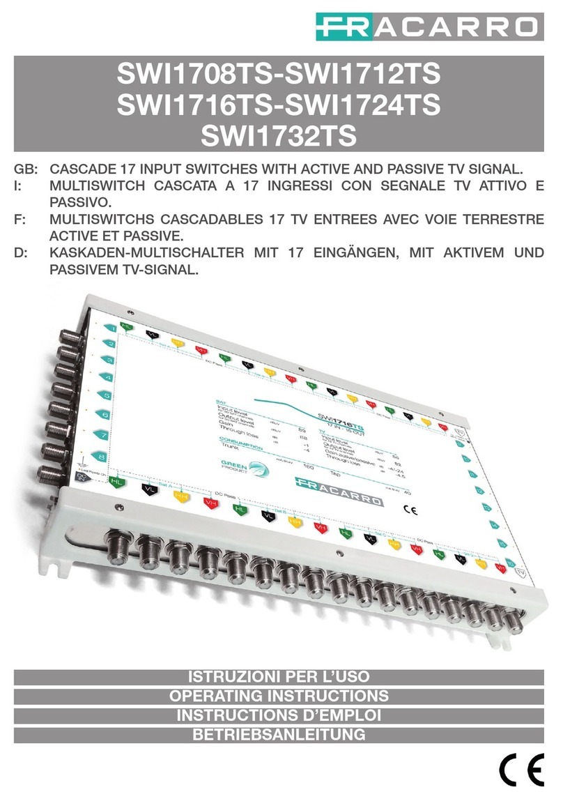
Fracarro SWI1732TS User manual

Fracarro

Fracarro SWI1732TS User manual

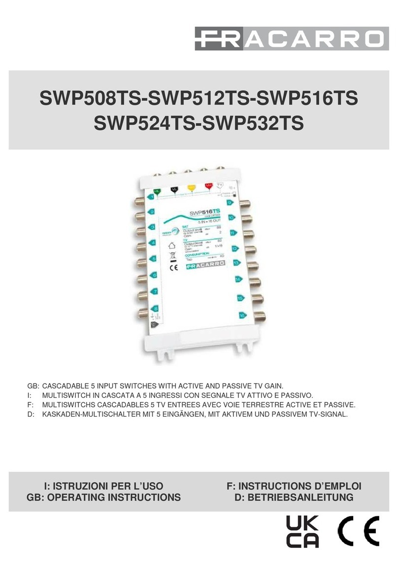
Fracarro SWP508TS User manual

Fracarro

Fracarro SWP508TS User manual

Fracarro Smart Switchline SWI85 STPLUS Series User manual

Fracarro

Fracarro Smart Switchline SWI85 STPLUS Series User manual

Fracarro SMART SWITCHLINE SWI85 PLUS Series User manual

Fracarro

Fracarro SMART SWITCHLINE SWI85 PLUS Series User manual

Fracarro SWP508QD User manual

Fracarro

Fracarro SWP508QD User manual

Fracarro SCD2-5416 User manual

Fracarro

Fracarro SCD2-5416 User manual

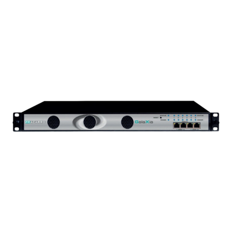
Fracarro GALAXIA User manual

Fracarro

Fracarro GALAXIA User manual

Fracarro XS5+ User manual

Fracarro

Fracarro XS5+ User manual

Fracarro SCD2-5216W User manual

Fracarro

Fracarro SCD2-5216W User manual

Fracarro SWI4532DT User manual

Fracarro

Fracarro SWI4532DT User manual

Fracarro SWI5906AS User manual

Fracarro

Fracarro SWI5906AS User manual

Fracarro XS4 Series User manual

Fracarro

Fracarro XS4 Series User manual

Fracarro SWI1308TS User manual

Fracarro

Fracarro SWI1308TS User manual

Fracarro SCD2-5216W User manual

Fracarro

Fracarro SCD2-5216W User manual

Fracarro SCD2-5416W User manual

Fracarro

Fracarro SCD2-5416W User manual

Fracarro SCD2-4216 User manual

Fracarro

Fracarro SCD2-4216 User manual

Fracarro SWP1708TS User manual

Fracarro

Fracarro SWP1708TS User manual

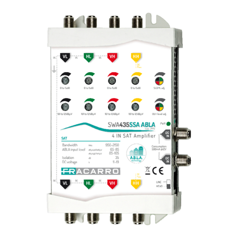
Fracarro AMP435SA User manual

Fracarro

Fracarro AMP435SA User manual

Fracarro SWP524TS User manual

Fracarro

Fracarro SWP524TS User manual

Popular Switch manuals by other brands

3Com ProCurve E4500-48 Getting started guide

3Com

3Com ProCurve E4500-48 Getting started guide

Endress+Hauser Liquiphant FTL51B operating instructions

Endress+Hauser

Endress+Hauser Liquiphant FTL51B operating instructions

LightwaveRF Connect LW430 instruction manual

LightwaveRF

LightwaveRF Connect LW430 instruction manual

Interlogix MC251-4P/1S user manual

Interlogix

Interlogix MC251-4P/1S user manual

Nortel Passport 8006 brochure

Nortel

Nortel Passport 8006 brochure

StarTech.com VS421HD4KA Quick install guide

StarTech.com

StarTech.com VS421HD4KA Quick install guide

Design CFM Installation & maintenance

Design

Design CFM Installation & maintenance

ZyXEL Communications ES-2108-G release note

ZyXEL Communications

ZyXEL Communications ES-2108-G release note

Mellanox Technologies MIS5600Q-10DNC Dismantling guide

Mellanox Technologies

Mellanox Technologies MIS5600Q-10DNC Dismantling guide

ANTAIRA LMP-2012G-SFP Series Quick installation guide

ANTAIRA

ANTAIRA LMP-2012G-SFP Series Quick installation guide

Korenix JetNet 4500 Series user manual

Korenix

Korenix JetNet 4500 Series user manual

Transition Networks Milan MIL-SM2401MAF user guide

Transition Networks

Transition Networks Milan MIL-SM2401MAF user guide

Intellinet 503907 user manual

Intellinet

Intellinet 503907 user manual

Draytek VigorSwitch PQ2200xb quick start guide

Draytek

Draytek VigorSwitch PQ2200xb quick start guide

Vega VEGACAP 66 operating instructions

Vega

Vega VEGACAP 66 operating instructions

Rose electronics UltraLink UL-DV3 Specifications

Rose electronics

Rose electronics UltraLink UL-DV3 Specifications

Jung AS 1280-1 Series operating instructions

Jung

Jung AS 1280-1 Series operating instructions

Chacon edisio ED-SH-03 manual

Chacon

Chacon edisio ED-SH-03 manual

manuals.online logo
manuals.online logoBrands
  • About & Mission
  • Contact us
  • Privacy Policy
  • Terms and Conditions

Copyright 2025 Manuals.Online. All Rights Reserved.