M.FD750TCR-00 27/03/2014
Pag. 2
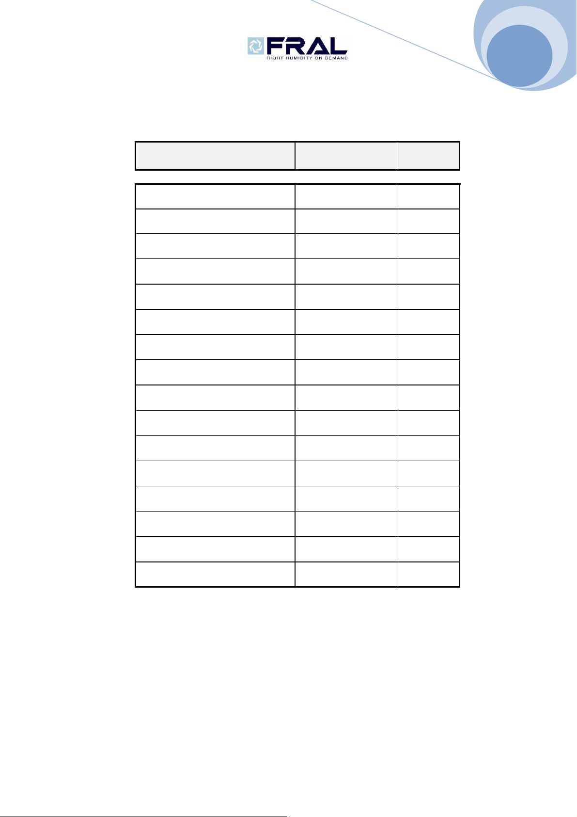
FD1000/S
FD980
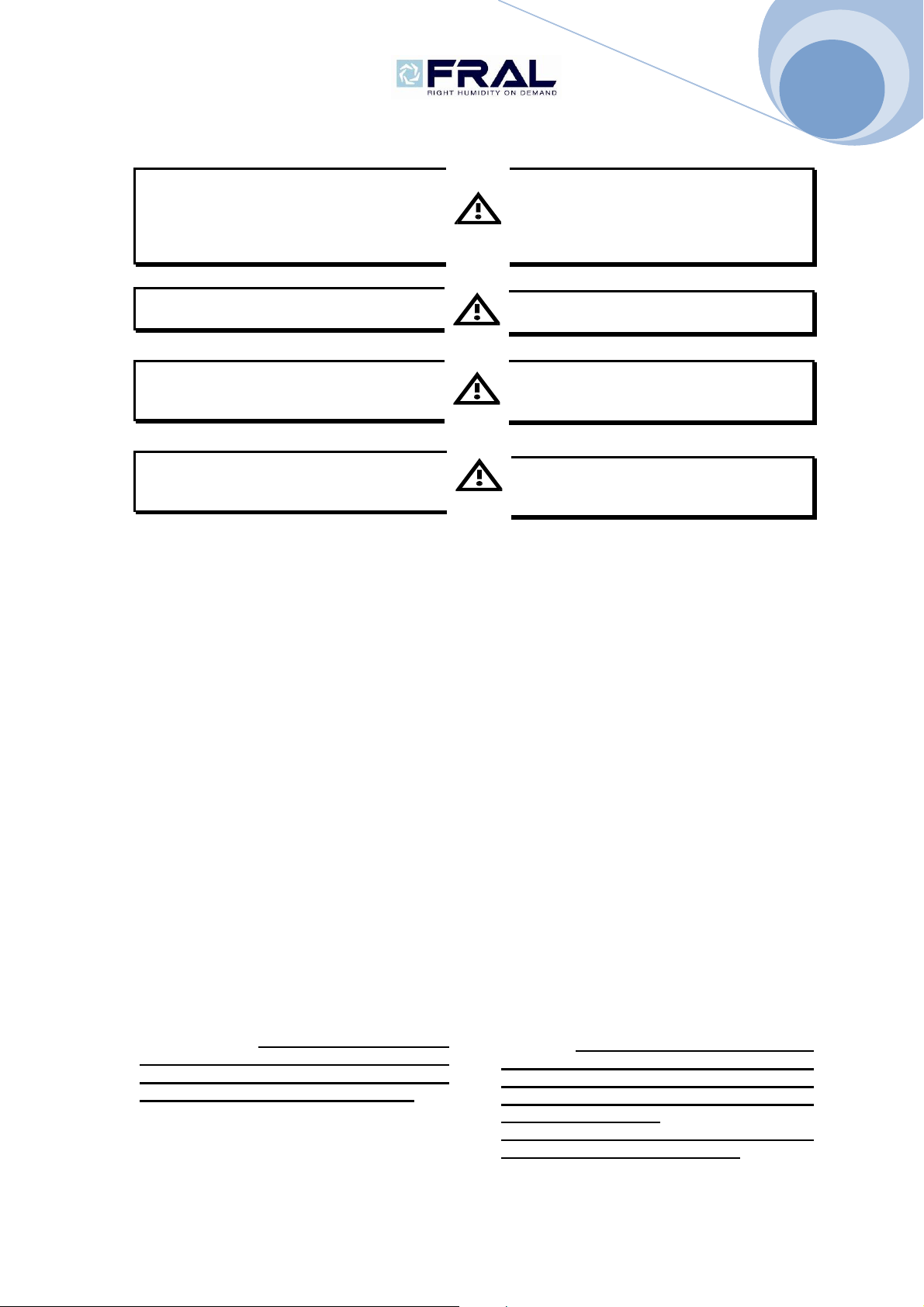
1.1 AVVERTENZE GENERALI
Installare in prossimità della macchina
una presa sezionata.
La linea elettrica di alimentazione deve
essere protetta da un interruttore
differenziale magnetotermico.
Non alterare o manomettere i dispositivi
di sicurezza.
Non dirigere spruzzi d’acqua sulle parti
elettriche o sull’involucro
dell’apparecchio.
Questo apparecchio è inadatto all’utilizzo
in atmosfere esplosive o potenzialmente
esplosive.
1.2 CONFORMITA’ ALLE DIRETTIVE
EUROPEE
L’apparecchio soddisfano i requisiti essenziali
contenuti nelle Direttive della Comunità Europea
2006/95/CE del 12 dicembre 2006 in materia di
sicurezza dei prodotti elettrici da usare in Bassa
Tensione; 2004/108/CE del 15 Dicembre 2004 in
materia di Compatibilità Elettromagnetica;
2006/42/CE del 17 maggio 2006 in materia di
sicurezza delle macchine.
La conformità è dichiarata con riferimento alle
seguenti norme tecniche armonizzate: CEI-EN
60335-2-40, CEI-EN 55014-1, CEI-EN 55014-2.
Si dichiara inoltre che il prodotto è fabbricato in
conformità alla Direttiva RoHS in vigore ovvero
(2011/65/UE del 08/06/2011) con riferimento alla
seguente norma tecnica armonizzata: CEI-EN
50581.
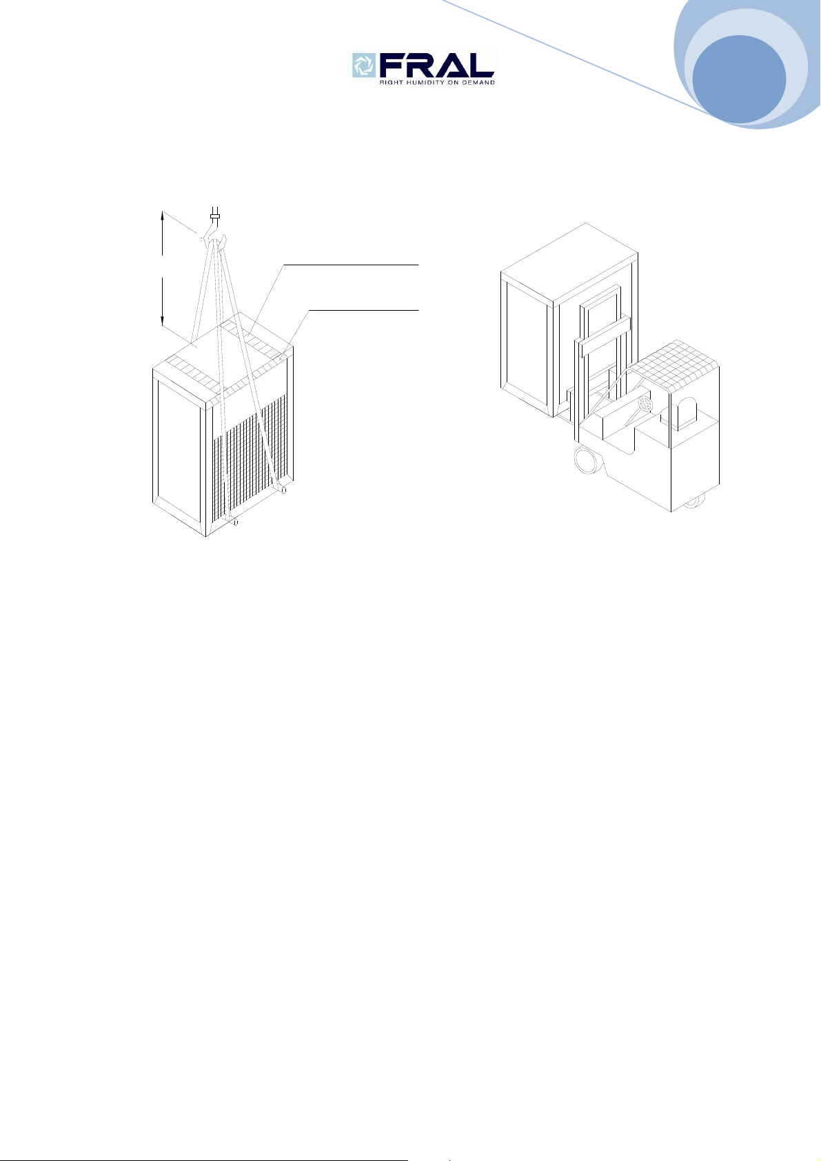
2. ISPEZIONE, TRASPORTO,
POSIZIONAMENTO
2.1 ISPEZIONE
All'atto del ricevimento dell'unità, verificarne
l'integrità: la macchina ha lasciato la fabbrica
in perfetto stato; eventuali danni dovranno
essere immediatamente contestati al
trasportatore ed annotati sul Foglio di
Consegna prima di controfirmarlo. La
nostra azienda dovrà essere messa al
corrente entro 8 giorni sull'entità del danno.
Il Cliente deve compilare un rapporto scritto
concernente ogni eventuale danno rilevante.
1.1 IMPORTANT WARNINGS
Close to the unit an switched electrical
plug must be present.
Main supply must be protected with a
differential switch.
Never modify settings of the safety
devices.
Never sprinkle water over the unit and its
electrical components.
This unit must not be used under
explosive atmosphere.
1.2 CONFORMITY TO EUROPEAN
DIRECTIVES
The machine has been designed, manufactured
and distributed by according to safety and electro-
magnetic compatibility to European Norms and
Regulations: MACHINES NORMS (2006/42/CE -
17.05.2006); SECURITY REGULATIONS FOR
LOW TENSION APPLIANCES 2006/95/CE -
12.12.2006; ELECTROMAGNETIC
COMPATIBILITY (EMC) – 2004/108/CE –
15.12.2004.
It is hereby certified that this Dehumidifier conform
to the: IEC Regulations CEI-EN 60335-2-40, CEI-
EN 55014-1, 55014-2.
The machine is built according to RoHS European
Norms: 2011/65/UE year 2011 and CEI-EN 50581.
2. INSPECTION,TRASPOT
AND SITE HANDLING
2.1 INSPECTION
After receiving the unit, immediately check its
integrity. The unit left the factory in perfect
condition; any eventual damage must be
questioned to the carrier and recorded on
the Delivery Note before it is signed. Our
firm must be informed, within 8 days, of the
extent of the damage.
The Customer must prepare a written
statement of any severe damage.