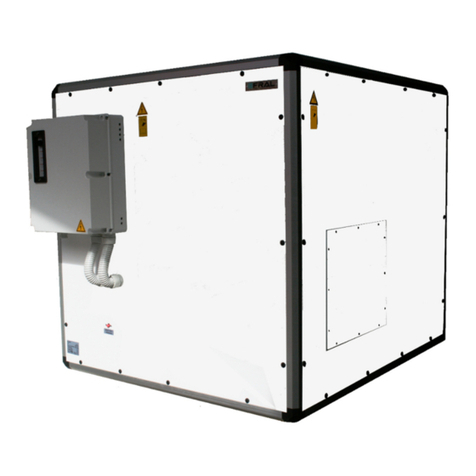
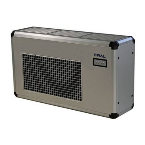
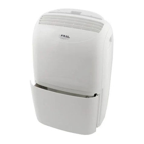
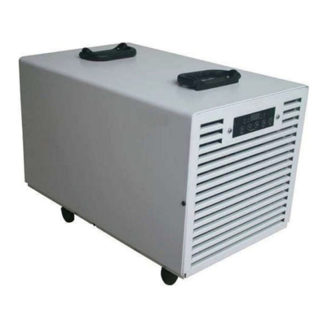
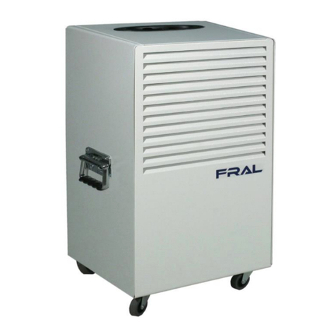
Fral FSW63 Series User manual

FSW 63
DEUMIDIFICATORE DA PISCINA
SWIMMING POOL DEHUMIDIFIER
FSW63
MANUALE TECNICO
TECHNICAL MANUAL
M.FSW63-14 Multilan ua e 01/03/2016

FSW 63
FSW63-14 Multilanguage 01/03/2016
27
TECHNICAL MANUAL
INDEX
INDEX .......................................................................................................................................................... 27
DECLARATION OF CONFORMITY ................................................................................................................. 29
Dehumidifiers FSW63 series .................................................................................................................... 29
UTILITY AND CONSERVATION OF THE MANUAL ......................................................................................... 30
NORMS REFERENCES .............................................................................................................................. 30
GENERAL SAFETY NORMS ....................................................................................................................... 31
PERSONAL PROTECTIVE EQUIPMENT ..................................................................................................... 32
UNIT DESCRIPTION...................................................................................................................................... 33
FRAME ..................................................................................................................................................... 33
REFRIGERANT CIRCUIT ............................................................................................................................ 33
CONDENSER AND EVAPORATORS ................................................................................................... 33
FINNED PAC .................................................................................................................................. 33
FINS ................................................................................................................................................. 33
TUBES .............................................................................................................................................. 33
COMPRESSOR ................................................................................................................................. 33
FANS ........................................................................................................................................................ 33
ELECTRIC BOX .......................................................................................................................................... 34
MICROPROCESSORS ................................................................................................................................ 34
Accessories.................................................................................................................................................. 34
Body machine completely in Inox ........................................................................................................... 34
Electric heaters in inox 2,0 W 230/1/50 (E.H): ..................................................................................... 34
Hot water coil (H.W.C) nominal capacity 2,4 W: .................................................................................. 34
3 Way electric valve ON/OFF (E.W): ....................................................................................................... 34
Remote control (humidostat) (On/Off): .................................................................................................. 34
Autorestart (On/Off): .............................................................................................................................. 34
H.D.G. defrost ......................................................................................................................................... 34
TECHNICAL DATA FSW ................................................................................................................................ 35
DRYING CAPACITY ....................................................................................................................................... 36
PERFORMANCE TABLES FSW63 .................................................................................................................. 36
FUNCTIONING LIMITS ................................................................................................................................. 37
CONTROL AND SAFETY DEVICES ................................................................................................................. 38
CONTROL DEVICES .................................................................................................................................. 38
THERMAL PROTECTION DEVICE (only for machines with electric heaters)............................................ 38

FSW63-14 Multilanguage 01/03/2016
28
FSW 63
INSPECTION, TRANSPORT AND SITE HANDLING ......................................................................................... 38
INSPECTION ............................................................................................................................................. 38
LIFTING AND SITE HANDLING ................................................................................................................. 39
UNPAC ING ............................................................................................................................................ 39
LOCATION ............................................................................................................................................... 39
WALL MOUNTING ................................................................................................................................... 40
CLEARANCES ............................................................................................................................................... 40
CONNECTION OF THE CONDENSED WATER DRAINAGE FITTING AND ELECTRICAL CABLE ........................ 41
CONNECTION TO THE HIDRAULIC CIRCUIT (only for post heating version) ............................................... 42
MAINTENANCE AND PERIODIC CHEC S ...................................................................................................... 42
IMPORTANT WARNINGS ......................................................................................................................... 42
AIR FILTER ............................................................................................................................................... 43
ELECTRICAL CONNECTIONS ........................................................................................................................ 44
Generality ............................................................................................................................................... 44
Main supply connection ......................................................................................................................... 44
Remote humidistat connections ............................................................................................................. 45
START UP ..................................................................................................................................................... 45
PRE-START CHEC ................................................................................................................................... 45
ELECTRONIC CONTROL AND FUNCTIONING ........................................................................................... 46
SIGNALLING PANEL ................................................................................................................................. 46
CONTROL PANEL ..................................................................................................................................... 47
GENERAL OBSERVATIOTIONS AND ADVISE ................................................................................................ 48
POWER SAVINGS ......................................................................................................................................... 49
DISPOSAL OF THE UNIT AT END OF ITS LIFE ............................................................................................... 49
TROUBLE SHOOTING ................................................................................................................................... 49
UNIT UNDER ALARM ............................................................................................................................... 50

FSW 63
FSW63-14 Multilanguage 01/03/2016
29
DECLARATION OF CONFORMITY
(Community directives Low Volta e and Electro-ma netic Compatibility)
FRAL Company s.r.l. Viale dell’Industria e dell’Artigianato 22/c – 35010 Carmignano di Brenta
– PD – hereby declares that the following products:
Dehumidifiers FSW63 series
have been designed, manufactured and distributed according to safety and electro-magnetic
compatibility of the European Norms and Regulations:
MACHINES NORMS (
2006/42/CE - 17.05.2006
) ;
SECURITY REGULATIONS FOR LOW TENSION APPLIANCES 2006/95/CE -
12.12.2006;
ELECTROMAGNETIC COMPATIBILITY (EMC) – 2004/108/CE – 15.12.2004.
It is hereby certified that this Dehumidifier conform to the:
IEC Regulations CEI-EN 60335-2-40, CEI-EN 55014-1, 55014-2.
The machine is built according to RoHS European Norms:
2011/65/UE year 2011 and CEI-EN 50581.
The Legal Agent
In . Alberto Gasparini

FSW63-14 Multilanguage 01/03/2016
30
FSW 63
UTILITY AND CONSERVATION OF THE MANUAL
This Manual conforms to the requirements of the Norms 98/37/CE and subsequent modifications.
The Manual gives all necessary indications required for the transport, Installation, start-up and
maintenance of the machines, which must be strictly followed by the user for a correct functioning of
the same.
To this purpose, the user must also strictly comply with the security norms described in the Manual.
The manual must always follow the machine and must be kept in a place which will guarantee its
perfect conservation for the proper use from the operator.
GRAPHIC SYMBOLS AND INDICATIONS INCLUDED IN THE MANUAL:
NORMS REFERENCES
The machines described in this manual have been designed according to the pertinent CE Norms, in
conformity with the MACHINES DIRECTIVES cited in the previous paragraph.
The machines are also complying with the essential requirements of the following European Rules and
Directives:
Machine Norms 2006/42 CE,
Electrical Safety Rules for the Low Tension Appliances 2006/95 CE,
Electromagnetic Compatibility 2004/108 CE,
Under Pressure Devices 97/23/CE.
Shows that ATTENTION must be paid to all procedures and operations to be carried
out for ensurin the correct functionin of the machine, describes the operations that
mus be avoided , and finally informs the operator about the correct procedure and
operations to be followed for the proper use of the machine.
This machine is desi ned in order to be installed in an internal environment.
In order to install it in an external environment please contact the headquarters.

FSW 63
FSW63-14 Multilanguage 01/03/2016
31
GENERAL SAFETY NORMS
When installing or servicing the unit, it is necessary to strictly follow the rules reported on this manual,
to conform to all the specifications of the labels on the unit, and to take any possible precautions of
the case for workers.
Pressure in refrigerant circuit and electrical equipment present in the unit can be hazardous when
installing or servicing the unit
Any intervention on the machine usin any instrument must be carried
out only
by a qualified technician.
The machine is IPX2 and it must be installed accordin with local norms and laws
of the place of installation.
Not observin the rules reported on this manual, and every modification to the
unit done without explicit previous authorisation, will cause the immediate
termination of the warranty.
Attention: before every operation of servicin on the unit, be sure that the
electric supply is disconnected. Never remove front grille or open any part of the
mac
hine without removing first the socket from the plug.
This machine has been desi ned and manufactured in compliance with the
strictest safety rules. Therefore, pointed instruments (screw drivers, wool
needles or similar ones) are not to be inserted in the rilles or in any other
openin of the panels, especially when it is opened to remove the filter.
Main supply must be protected with a differential switch.
Close to the unit a switched electrical plu must be present, accordin with
local laws and norms.
Never modify settin s of the safety devices.
Never sprinkle water over the unit and its electrical components.
The machine must not be cleaned usin water. To clean the machine use a wet
cloth. Remember to disconnect the plug from the socket before.
When the machine is connected with a power socket, it must be in vertical
position and any rou h move must be avoided because it could cause some
water to come into contact with electrical parts; it is, therefore, recommended
to remove the plu from the socket before movin around the machine; if any
water may have been spread on the machine, followin some rou h handlin
of the same, then, the machine must be turned off and can be started up a ain
only after 8 hours.

FSW63-14 Multilanguage 01/03/2016
32
FSW 63
PERSONAL PROTECTIVE EQUIPMENT
When operating and maintaining the FSW unit, use the following personal protective equipment.
Equiment: people who make maintenance or work with the unit, must wear an
equipment in accordance with the safety Directives. They must wear accident
prevention shoes with anti-slip sole where the paving is slippery.
Gloves: During the cleanings and the maintenance operations, it’s necessary the use of
appropriate gloves. In case of gas recharge, It’s complulsory the use of appropriate
gloves to avoid the rick of freezing.
Mask and goggles: Respiratory protection (mask) and eye protection
(goggles) should be used during cleaning and maintenance operations.
SAFETY SIGNS
The equipment features the followin safety si ns, which must be complied with:
General hazard
Electric shock hazard
It must not be used under explosive atmosphere.
Machine is not desi ned to be used by people (also children) whose physical,
sensory or mental capabilities are reduced. Also people without experience or
knowled e of the machine can’t use it.
People, described above, can use this machine only if there’s someone,
responsable of their safety, which watches them and ives them instruction
re ardin the use of the machine.
Children must be watched in order to be sure they don't play with machine.
This machine is desi ned in order to be used by experienced users or trained in
shops, li ht industry and farms.
People without experiences can use this machine only for a commercial use.
This machine must be always connected usin earthed electrical plu s as
required for all electrical appliances; FRAL Company declines any
responsibility for any dan er or dama e whenever this norm is not
complied with.

FSW 63
FSW63-14 Multilanguage 01/03/2016
33
UNIT DESCRIPTION
FRAME
All FSW units are made from galvanised thick sheet metal, painted with polyurethane powder
enamelat 180°C to ensure the best resistance against the atmospheric agents. The frame is self-
supporting
REFRIGERANT CIRCUIT
The refrigerant gas used in these units is R410A. The refrigerant circuit is made in according to ISO
97/23 concerning welding procedures and PED regulation.
The refrigerant circuit includes:
•filter drier.
•schrader valves form maintenance and control.
•capillary expansion.
•compressor.
CONDENSER AND EVAPORATORS
FINNED PACK
It consist of copper tubes mechanically expanded into aluminium or copper fins provided with full
collars that allow their regular spacing. The best heat transmission is guaranteed by the fin collars that
completely cover the tubes.
FINS
They are manufactured by high precision pressing of aluminium, aluminium epoxy painted, copper or
pretinned copper sheets. The fin shape is slightly corrugated in order to improve the heat exchange
transmission coeffi cient without heavily affecting the air pressure drop. Furthermore a good water
draining is assures and the inside dust accumulation is avoided.
TUBES
For the heat exchangers high quality copper tubes are used. The tubes are suitable for the majority of
the primary refrigerants in both cold and warm working conditions.
COMPRESSOR
The compressor is rotative type.
The characteristics of the compressor are the follow:
1. High efficiency for saving energy consumption
2. Low sound level ,quiet operation
3. Applied HFC refrigerant for protecting environment
4. High reliability, long lifetime.
FANS
Centrifugal fan type.

FSW63-14 Multilanguage 01/03/2016
34
FSW 63
ELECTRIC BOX
The electric switch board is made according to electromagnetic compatibility norms (2004/108 CEE)
and Electrical Safety Rules for the Low Tension Appliances 2006/95 CEE.
Inside the electric box there are the following components:
1. Terminals for remote control;
2. Electronic board;
The installation must provide a general switch if necessary, according with local laws and norms.
MICROPROCESSORS
The microprocessors check all the function of the machine like: General functioning, automatic
defrost system, alarms and set point of the humidty and temperature (temperature only for machine
with hot water coil Version).
Accessories
Body machine completely in Inox
Electric heaters in inox 2,0 kW 230/1/50 (E. ):
Armored electric heaters in inox, it is able to transfer the 90% of the convective heat in way evenly.
ot water coil ( .W.C) nominal capacity 2,4 kW:
This battery can help you in heat the environment of the swimming pool thanks its efficient water hot
coil due to the narrow step fins. It is possible to assure a nominal capacity of 2,4 kW with a
environmental temperature of 27°C and an inlet water temperature between 60 and 70°C.
3 Way electric valve ON/OFF (E.W):
Control of the flow water inside the hot water coil
Remote control (humidostat) (On/Off):
It is possibile to use a remote control with the machine. In this case must be used a remote
humidostat to be connected to the terminal boxes of the electric panelboard in place of the
standard humidostat. It is also possible to have an ON-OFF switch to be electrically connected in
series to the humidostat.
Autorestart (On/Off):
If is ON State network fails or machine is unplugged, the values of set point, delay counter, defrost
counter, hour counter and any other operating parameters are stored and, when power comes back,
everything continues as before.
.D.G. defrost
This machine allows to realize the hot gas defrost.

FSW 63
FSW63-14 Multilanguage 01/03/2016
35
TECHNICAL DATA FSW
Mod. FSW63
FSW63.005 FSW63.003 FSW63.006
FSW63.008 FSW63.007
Indez Protection (IP) IPX2 IPX2 IPX2 IPX2
Drying capacity
(1)
L/24h 63 63 63 63
Nominal power consumption without
heaters
(2)
kW 0,84 0,84 0,84 0,84
Nominal power consumption with
heaters
(2)
kW / 2,84 / 2,84
Maximum power consumption without
heaters
(3)
kW 0,97 0,97 0,97 0,97
Maximum power consumption with
heaters
(3)
kW / 3,00 / 3,00
Max.current consumption without
heaters
(3)
A 4,4 4,4 4,4 4,4
Max.current consumption with heaters
(3)
A / 13,3 / 13,3
Electric heater power (otional) kW / 2,0 / 2,0
Hot water coil capacity (optional) kW / / 2,2 /
Nominal Air flow m3/h 600 600 600 600
Available static pressure Pa 40 40 40 40
Refrigerant charge Tipo R410A R410A R410A R410A
Defrost type Type Air Air Air HGD
Sound pressure level
(4)
dB(A) 49 49 49 49
Temperature operating range
°C 5÷35 5÷35 5÷35 1÷35
Humidity operating range % 45÷99 45÷99 45÷99 45÷99
Condensate draining connection INCH’’ ¾” ¾” ¾” ¾”
Hot water coil connection (Only for
models with H.W.C.) INCH’’ / / ½” /
Width mm 1008 1008 1008 1008
Depth mm 231 231 231 231
Heigth mm 605 605 605 605
Operating weight g 47 47 47 47
Nominal power supply V/ph/Hz 230/1~/50 230/1~/50 230/1~/50 230/1~/50
(1) Referred to: inlet air temp. 32 °C relative humidity 90%.
(2) Referred to: inlet air temp. 26,7 °C relative humidity 60%.
(3) Referred to: inlet air temp. 35 °C relative humidity 70%.
(4) Sound power level calucated in 3m free field.

FSW63-14 Multilanguage 01/03/2016
36
FSW 63
DRYING CAPACITY
Ambient Temperature °C
5 10 252015 30
4 0
C o n d e n s e d W a te r L ite rs/ 2 4 H o u rs
1 0 2 0 3 0
6 3
5 0
F S W
6 0
6 0
5 0 R .H . 7 0 8 0
PERFORMANCE TABLES FSW6
CONDENSED WATER AT DIFFERENT ROOM TEMPERATURE AND HUMIDITY CONDITIONS
Room condition Condensed water Room condition Condensed water
10°C-60% 10 l/24h 25°C-60% 25 l/24 h
10°C-80% 18 l/24h 25°C-80% 35 l/24 h
15°C-60% 15 l/24 h 27°C-65% 28 l/24 h
15°C-80% 23 l/24 h 27°C-80% 39 l/24 h
20°C-60% 20 l/24 h 30°C-80% 52 l/24 h
20°C-80% 28 l/24 h 32°C-90% 63 l/24 h

FSW 63
FSW63-14 Multilanguage 01/03/2016
37
FUNCTIONING LIMITS
Following Diagram represents FSW units application .
Operatin Table – standard units
It is stron ly recommended to let the units operate within the below reported
limits. Exceedin these limits it is not ranted neither normal operation nor unit
reliability and inte rity (for special applications, please contact our Company).

FSW63-14 Multilanguage 01/03/2016
38
FSW 63
CONTROL AND SAFETY DEVICES
CONTROL DEVICES
All the control devices are tested on factory before the unit is delivered.
Their operating mode is described in the following paragraphs.
THERMAL PROTECTION DEVICE (only for machines with electric
heaters)
The machine is provided with a safety thermostat which switches off the heaters if the supply air
temperature is too high. In such case the led "Heat" remains on but the heaters does not work and
the air is no longer heated.
In order to reactivate the resistors, the safety device must be reset through the push button which is
located in the black box below the control panel. To access it, disconnect the power supply and, after
removing the cover, unscrew the protective cap with the help of a screwdriver.
INSPECTION, TRANSPORT AND SITE HANDLING
INSPECTION
After receiving the unit, immediately check its integrity. The unit left the factory in perfect condition;
any eventual dama e must be questioned to the carrier and recorded on the Delivery Note before it
is si ned. Our firm must be informed, within 8 days, of the extent of the dama e.
The Customer must prepare a written statement of any severe dama e.
The machine must not be set runnin in narrow areas, which do not allow a
proper diffusion in the room of the air comin out from the rille. It is, instead,
allowed to set the machine on the sides near the walls.
The front panel should not be used to lay over it cloths or other thin s: it could
cause dama es or dan ers.

FSW 63
FSW63-14 Multilanguage 01/03/2016
39
LIFTING AND SITE HANDLING
The lifting is obtained by using a forklift: fork must be inserted in the base pallet, and care must be
taken in order that the fork does not hit the section base or panel (see the picture below).
To unload the unit with a crane, pass bars under the machine and attach the necessary cable or chain
lifting devices to the bar, ensuring that they are clamped firmly; protect the sides of the chiller with
boarding or material of a similar nature.
UNPACKING
When unpacking the unit pay attention not to damage the unit.
The package is made up by different materials: wood, paper, nylon etc.
It’s a good rule to keep them separately and deliver to the proper collecting centre in order to reduce
their environmental impact.
LOCATION
Consideration must be given to the following points when determining the most suitable site for
the unit installation:
location arrangement in order to guarantee adequate air flow (no narrow spaces)
electrical power sup ply location;
accessibility for servicing/maintenance and repair of the unit and/or its components;
floor loading strength and ability to support the operating weight of the unit;
possible objection to operating noise.
The machine respects the previus declaration of conformity only if it’s
re
stin on the
round. If the machine is fixed to the wall it’s necessary to install a plate in order to
respect the declaration of conformity. This plate must be ordered on demand.
This machine is desi ned in order to be installed in an internal environment.
In order to install it in an external environment please contact the headquarters.
The place of installation must be chosen in
order to avoid water oes inside the
appliance.
This machine can’t be installed in laundries.
This machine can’t be installed in places which are easily accessible from the
public.

FSW63-14 Multilanguage 01/03/2016
40
FSW 63
WALL MOUNTING
Please look the picture here below in order to understand like to mount the machine on the wall,
there are two holes behind the machine that can be used for hanging the machine on the wall with
the correct screws for the support of the machine.
CLEARANCES
Absolute care must be taken to ensure adequate air volume to the air intake and fan discharge,
and to avoid air recirculation through the unit that will deeply reduce its performances.
For these reasons it is necessary to observe the following clearances (see the pictures in the
following pages):
- air filter suction side: 1 metre min.
- top side: 1 metre min
FOR USE IN SWIMMING POOLS KEEP DISTANCES FROM WATER ACCORDING
WITH SAFETY NORMS (MACHINE IS IPX2)
1 m
1 m

FSW 63
FSW63-14 Multilanguage 01/03/2016
41
CONNECTION OF THE CONDENSED WATER DRAINAGE FITTING AND
ELECTRICAL CABLE
Connect condensed water drainage fitting (¾’’ M) to a draining pipe.
It should be always avoided to form a doubble siphon, which could obstruct the water flowing
with the consequent risk of flooding the area.
Removing the case in order to insert the pipe and electrical cable like represented here below.
6 Unscrew casin 's screw.
7 Remove the casin .
8 Spin condensation pipe.
9 Remove plastic cover. 10 Connect power and remote humidostat wires.

FSW63-14 Multilanguage 01/03/2016
42
FSW 63
CONNECTION TO THE HIDRAULIC CIRCUIT (only for post heating
version)
When you o to connect the inlet and outlet water pipe
(postheatin battery), hold the connector with properly key to
prevent twistin and breaka e of the pipes
Fittings are ½”.
MAINTENANCE AND PERIODIC CHECKS
IMPORTANT WARNINGS
All this operation
s
described in this chapter MUST BE
DONE BY TRAINED PEOPLE ONLY
.
WARNING: Inside the unit some movin components are present. Be very
careful when operatin in their surroundin s even if the electric supply is
disconnected.
WARNING: The unit should be installed so that maintenance and/or repair services be
possible. The warranty does not cover costs due to liftin apparatus, platforms or other
liftin systems required by the warranty interventions.
WARNING: The top shell and dischar e line of compressor are usually at hi h
temperature level. Be very careful when operatin in their surroundin s.
WARNING: Aluminium coil fins are very sharp and can cause serious wounds. Be very
careful when operatin in their surroundin s.
WARNING: After servicin operation close the unit with cover panels, fixin
them
with lockin screws.

FSW 63
FSW63-14 Multilanguage 01/03/2016
43
AIR FILTER
All this operation described in this chapter MUST BE DONE BY TRAINED PEOPLE
ONLY.
Before every operation of servicin on the unit, be sure that the electric supply has
been disconnected.
In the inner side of
the unit movable parts are present. Be very careful when
operatin in their surroundin s.
Aluminium coil fins are very sharp and can cause serious wounds.
Be very careful when operatin in their surroundin s.
After servicin
operations, close the unit with cover panels, fixi
n them with lockin
screws.

FSW63-14 Multilanguage 01/03/2016
44
FSW 63
ELECTRICAL CONNECTIONS
Generality
It must be verified that electric supply is corresponding to the unit electric nominal data
(tension, phases, frequency) reported on the label in the front panel of the unit.
Power connections must be made using a three-wire cable + neutral wire + ground cable.
Ground connection is compulsory. Installer must connect ground cable with a dedicated
terminal on the apposite terminal block.
Main supply connection
The Electric Power Supply Connection must be carried out according to the indications given in
the Electric Diagram, by connecting the cable supplied with the machine and according with
safety norm.
Models FSW63 must be electrically powered with 1 phase-neutral-earth.
Machine must be installed respectin the national rules
re ardin plants.
This machines
series belon s to the electric appliances
functionin at low tension
(230
V).
Before every operation on the electric section, be sure that the electric supply is
disconnected.
Main supply must be prote
cted with a differential switch.
Close to the unit a main switch must be present.
Power cable and line protection must be sized accordin norm and laws accordin
with absorbed current of the machine (see technical data).
The line volta e fluctuations must not be more t
han ±5% of the nominal value, while
the volta e unbalance between one phase and another must not exceed 2%. If those
tolerances should not be respected, please contact our Firm to provide proper devices.
Electric supply must be in the limits
shown: in the opposite case warranty will
terminate immediately.
Electrical connections therefore must be always done accordin to the instructions
reported on the wirin dia ram enclosed with the unit and norms and laws.

FSW 63
FSW63-14 Multilanguage 01/03/2016
45
Remote humidistat connections
Remote humidistat connection must be realised according with electric diagram.
Connections must be done according to the electric wiring diagram specifications.
START UP
PRE-START CHECK
It’s very important to keep round wire lon er than the others: in this way if the cable
is pulled, the round wire is the last to be removed.
Since there’s no fixin device for the main supply, the power cable must be fixed wit
h
cable ducts or similar. The cable duct must enter inside the machine throu h the
apposite holes.
Machine is not desi ned to be used by people (also children) whose physical,
sensory or mental capabilities are reduced. Also people without experience or
knowled e of the machine can’t use it.
People, described above, can use this machine only if there’s someone, responsable
of their safety, which watches them and ives them instruction re ardin the use of
the machine.
Children must be watched in order to be sure they don't play with machine.
This machine is desi ned in order to be used by experienced users or trained in
shops, li ht industry and farms.
People without experiences can use this machine only for a commercial use.
Check that all power cables are correctly connected and
all terminals are fastly fixed.
The volta e at the phase,
must be the o
ne indicated on the unit label
± 5%
tolerance. If this should not happen, please, contact our Factory.
Caution:
before proceedin to start up, check that all the cover panel be located in
the proper position and locked with fastenin screws.
This manual suits for next models
6
Table of contents
Other Fral Dehumidifier manuals