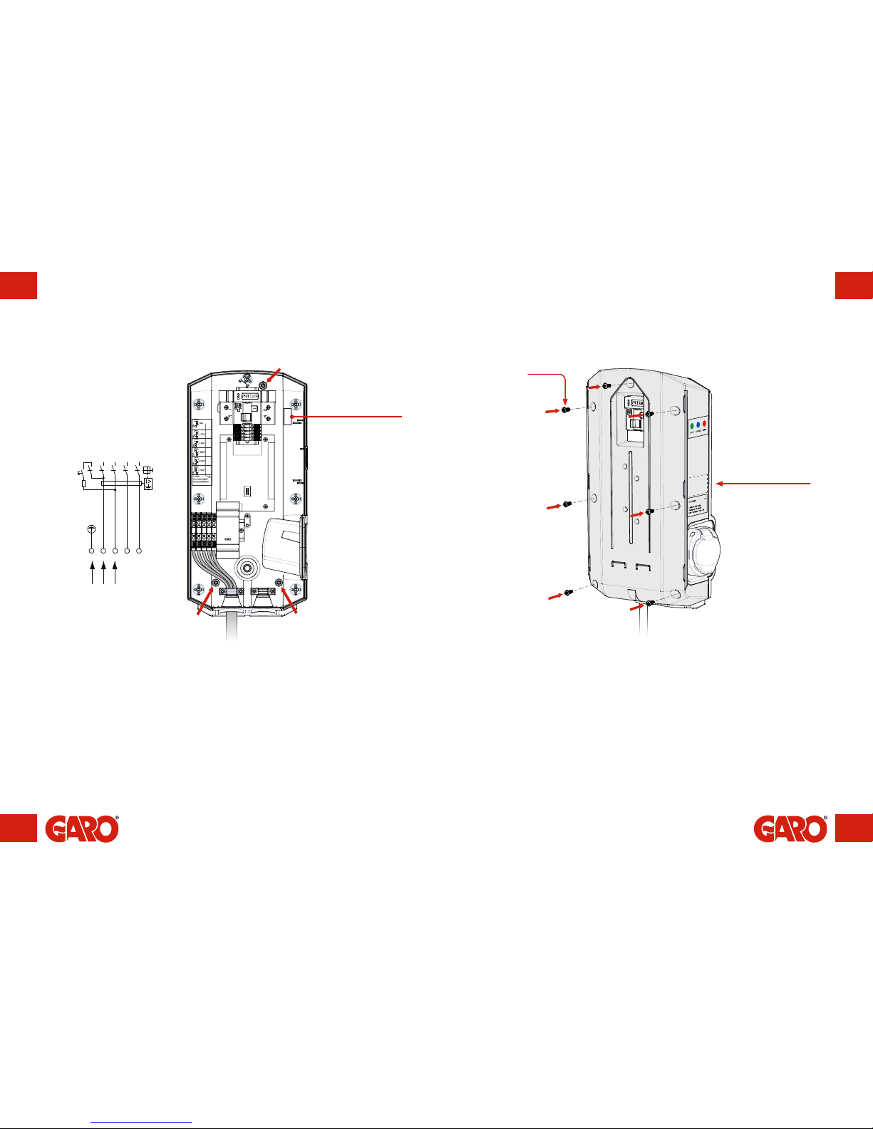
INC. TERMINAL
30mA
(figure 7)
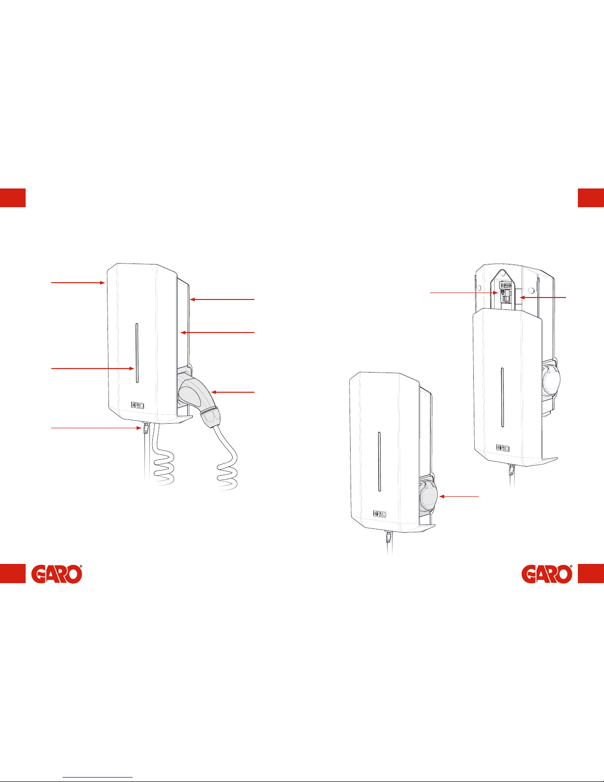
language labels
are placed on the side
(figure 8)
Serial no./SSID
password
(Wi-Fi version only)
For incoming single-phase supply
(16A, 240V or 32A, 240V) on
a three-phase GLB, the incoming
phase is channelled to connection
block L1.
8. Screw the base box onto the wall using three screws suitable for the wall
surface. See the red arrows in figure 6.
9. Feed the cable through the cable inlet.
10. Connect the cable onto the connection blocks. The connection blocks are
compatible with cables measuring 1.5 mm²–6 mm², and up to 10 mm² in the
32A Wallbox.
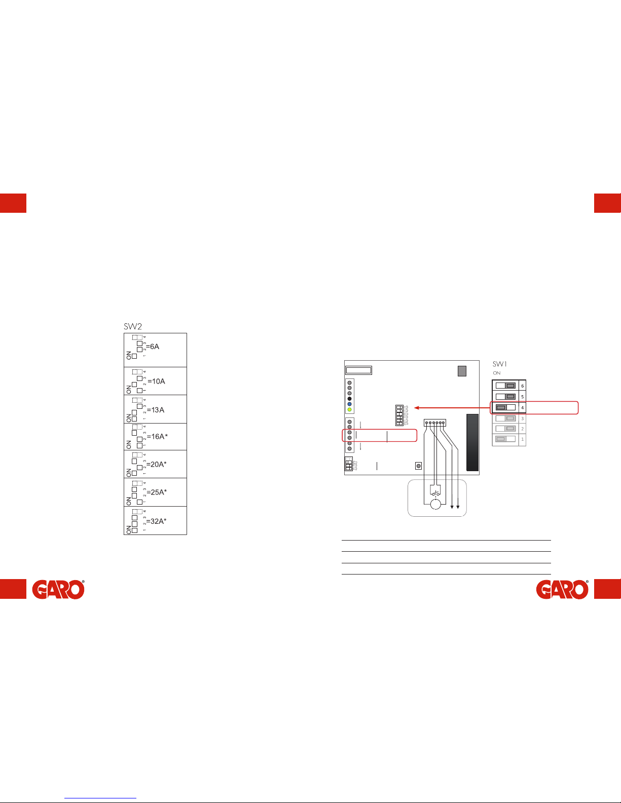
11. Does the charging current need to be reduced? Refer to section: Reducing
charging current.
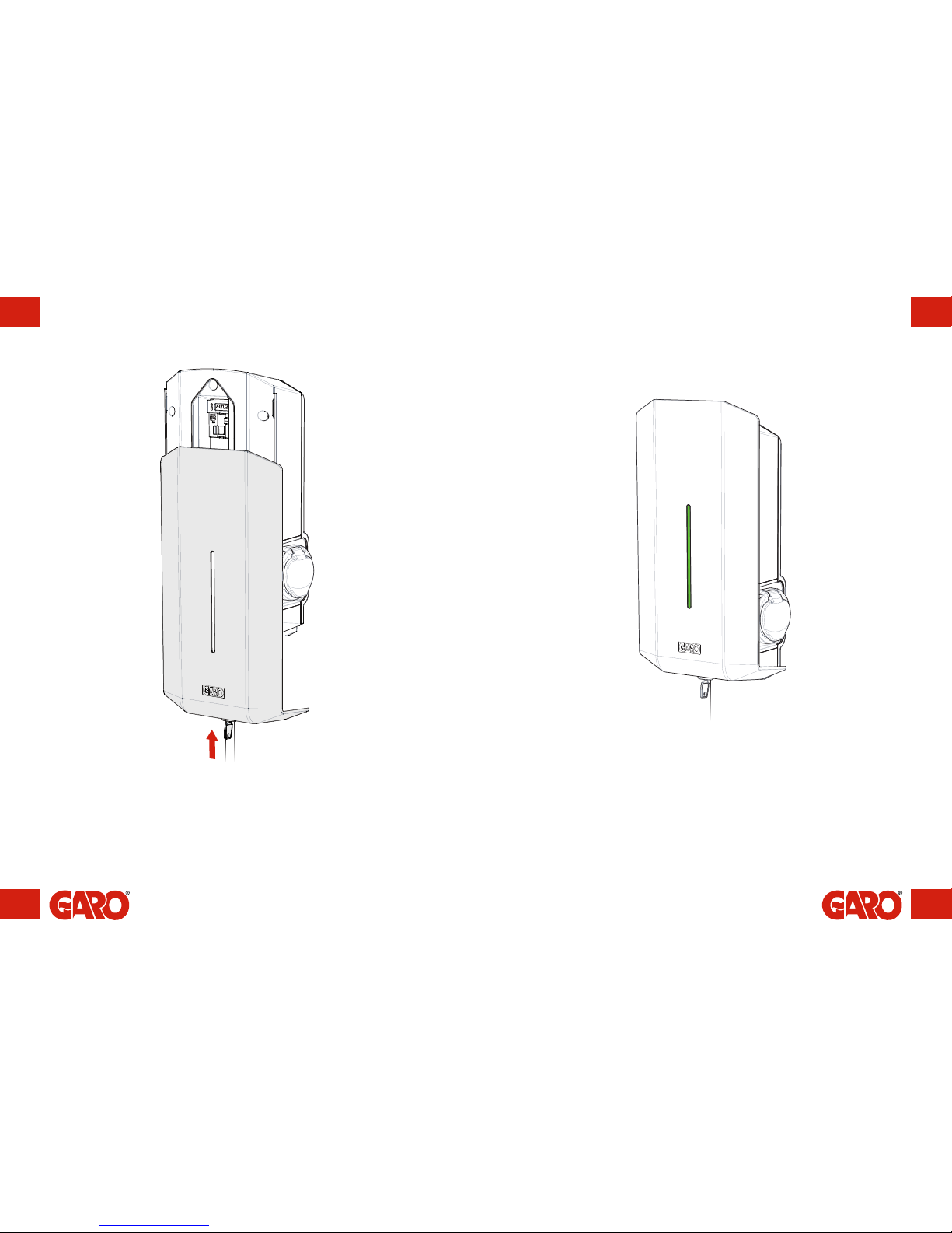
12. Carefully place the cover in position from the front. Ensure the inserts on the right
hand side fit into the groove and that it looks correct. If the charger has Wi-Fi
connectivity, verify that the SSID numbers on the cover and base plate match.
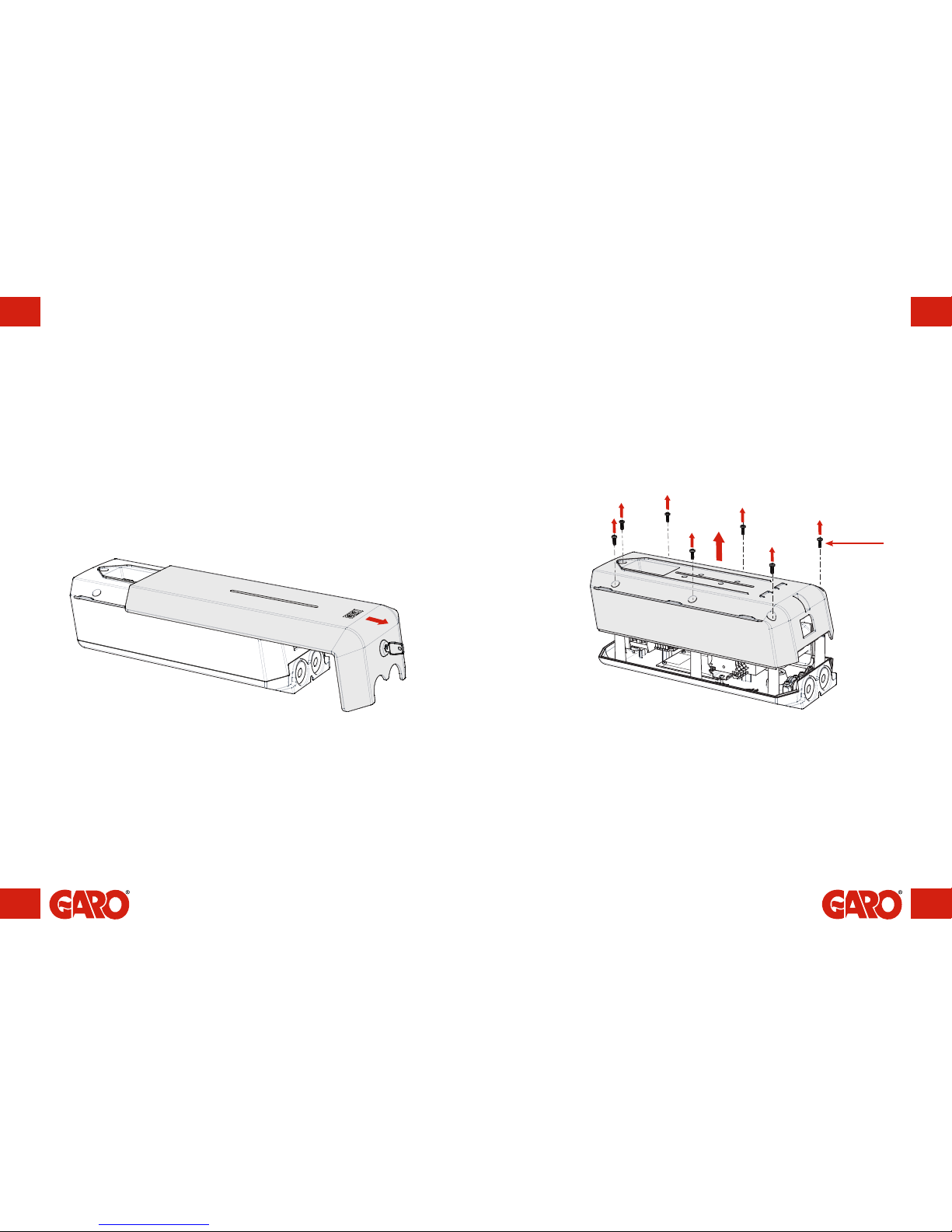
13. Securely attach the cover using the seven screws.
14. Verify that the personal protective/residual-current circuit breaker is switched on.
T20