GARO Wallbox GLB Series User manual

EN
GARO Wallbox GLB
Assembly instructions / End User Instruction (EN)
manual 380185 4.0

EN
2
TABLE OF CONTENT
About this manual 3
Safety Information 3
Installation Instructions 6
Box Contents 7
Tools and Materials Required 8
Step-by-Step Guide 10
Remote Control function 17
Dynamic Load Management (DLM) for Stand-Alone GLB-Wallbox 18
Dynamic Load Management (DLM) for GLB-Wallboxes in group 21
Installing the RFID reader 24
RFID for multiple GLB-Wallboxes in group 26
LAN connection via RJ45 port on communication card (only for GLB-Wallbox with communication card installed) 28
Mainboard simplified connection diagram 29
Dimensional drawing 30
END USER INSTRUCTION 31
Charging electric vehicles 31
Resetting/Conditioning of RCCB or RCBO 33
Connecting to the wallbox’s Wi-Fi access point (AP) 34
Web interface 35
Dynamic Load Management (DLM) settings in the web interface (1pcs installed DLM energymeter) 37
Dynamic Load Management (DLM) settings in the web interface (2pcs installed DLM energymeter) 38
RFID settings in the web interface 39
Connect GLB-Wallbox to a local network via Wi-Fi 40
Connect GLB-Wallbox to a local network via ethernet using DHCP-server 41
Connect GLB-Wallbox to a local network via ethernet using static 42
IP-address 42
Firmware update process for GLB Wallbox connected to internet via Wifi or LAN 43
Firmware update for GLB Wallbox not connected to internet via Wifi or LAN 43
Care 44
Troubleshooting 45
Technical data 47

EN
3
The purpose of this Manual is to provide you with the necessary information to install and use your
Garo Wallbox, model GLB
This document contains general descriptions which are verified to be accurate at the time of printing.
However, because continuous improvement is a goal at GARO, we reserve the right to make product
modifications at any time.
This range is subject to continual product development. Errors, typo and omissions excepted.
Latest manual can always be found at www.garoemobility.com/support
About this manual
Hazard categories and special symbols
Read these instructions carefully before trying to install, operate, or maintain the GLB Wallbox.
Indicates a potentially hazardous situation which could result in death or serious injury
Indicates a potentially hazardous situation which could result in minor or moderate injury
Indicates practices that do not involve the risk of bodily injury
Safety Information
Warnings
This equipment should not be used by anyone (including children) with reduced physical,
sensory or mental capacity, or anyone lacking in experience or knowledge, unless they are
provided with supervision or prior instruction in how to use the equipment by the person
responsible for their safety.
The GLB Wallbox range of charging stations is designed exclusively for charging electric
vehicles.
The GLB Wallbox must be grounded through a permanent wiring system.

EN
4
Do not install or use the GLB Wallbox near flammable, explosive, harsh, or combustible
materials, chemicals, or vapors.
Turn off input power at the circuit breaker before installing, configuring or cleaning of the GLB
Wallbox.
Use the GLB Wallbox only within the specified operating parameters.
Never spray water or any other liquid directly at the GLB Wallbox. Never spray any liquid
onto the charge handle or submerge the charge handle in liquid. Store the charge handle in
the dock to prevent unnecessary exposure to contamination or moisture.
Do not use this equipment if it appears to be damaged or if the charging cable appears to be
damaged.
Do not modify the equipment installation or any part of the product.
Do not touch the GLB Wallbox’s terminals with fingers or any other objects.
Do not insert foreign objects into any part of the GLB Wallbox
Cautions
Do not use private power generators as a power source for charging.
Incorrect installation and testing of the GLB Wallbox could potentially damage either the
vehicle’s Battery and/or the GLB Wallbox itself.
Do not operate the GLB Wallbox in temperatures outside its operating range – see technical
data.
Notes
All installation must be carried out by an authorized installer and comply with local installation
regulations.
Ensure that the GLB Wallbox’s charging cable is positioned so it will not be stepped on, driven
over, tripped on, or subjected to damage or stress.

EN
5
Unroll the charging cable to prevent it from overheating.
Do not use cleaning solvents to clean any of the GLB Wallbox’s components. The outside
of the GLB Wallbox, the charging cable, and the end of the charging cable should be
periodically wiped with a clean, dry cloth to remove accumulation of dirt and dust.
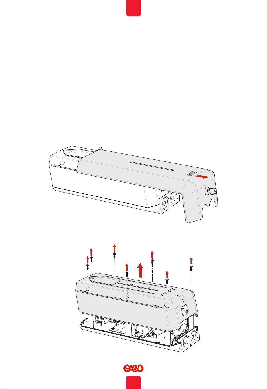
Be careful not to damage the circuit boards or components during installation.
Refer to local standards and regulations not to exceed charging current limitations.
Adapters for charging connectors are not allowed to be used.
Cord extension sets for charging cable are not allowed to be used.
To even out the load, it is important to rotate the phases when connecting several of GLB
wallboxes to the same supply. Note that 1-phase charging is common in electric vehicles and
L1 the GLB is used for this purpose.
Ventilation signal from EV is not supported.
Cord extension sets for charging cable is not allowed to be used.
Electrical vehicles (EV) software and the GLB Wallbox firmware are continuously updated.
To make sure that the GLB wallboxis working properly, it is necessary to update the firmware
and it requires a communication card.
Communication cards are available as an accessory.
GLB Wallboxes installed in a cluster only need the
master to have the communication card installed.

EN
6
Installation Instructions
INSTALLATION INSTRUCTIONS
Mandatory: Supply cable, 1-phase or 3-phase depending on GLB model
Cable entrance from bottom side
Custom (only when extra functions in use):
• Twisted pair cable for Modbus energy meter
• Twisted pair cable for Datalink communication
• 2-wire signal cable for remote control function
• TP Cat6 for LAN connection

EN
7
Installation Instructions
EN
GARO Wallbox
Assemblyinstructions/User Instructions (EN)
380175-3
Box Contents
Language labels
GLB Wallbox
Keys
Drill template
(see the back of the box)
Manual

EN
8
Installation Instructions
353116
GLB-T222WO
230/400V 32A 50Hz
IP44 EN 61851-1 IEC61439-7 AEVCS
SN: 5022254
BOX 203, 335 25 GNOSJÖ, SWE
Before installing the Garo GLB-Wallbox, gather the following tools and materials:
• Pen or marker
• Hole punch (optional, to push through cardboard template)
• Wire cutter
• Voltmeter or digital multimeter (to measure AC voltage at the installation site)
• Small flathead screwdriver
• Medium flathead screwdriver
• Large flathead screwdriver (optional, to remove plastic knock-outs on backside of GLB Wallbox)
• T20 Torx driver
• 3 screws (and plugs) suitable for wall type
• Ferrules (the diameter of the ferrule depends on the diameter of the power wiring and the
construction)
• Level
• Power drill
• Twisted pair cable (Optional only when DLM is used) Cable: Suitable for Modbus communication.
• Cable gland for communication cable (Optional only when knock-outs on backside of GLB
Wallbox is used)
Tools and Materials Required
Important Information
The GARO GLB Wallbox is an AC charge-station enabling Mode 3 charging which complies fully
with the requirements of IEC 61851-1 and IEC TS 61439-7. The product complies with IP Code
IP44, with a closed front.
It is to be fitted to a wall or GARO Wallbox stand, and all installation must be carried out by an
authorized installer and comply with local country installation regulations.
(figure 1)
Type Label example
GLB Type

EN
9
Installation Instructions
1) Chargers without RCCB or RCBO included in the enclosure must have Residual Current
protection and must be protected with a max 32A fuse in the supply distribution box.
2) Chargers without RCCB Type B fitted or DC fault protection in the enclosure must in
accordance to IEC 60364-7-722 be protected with a Residual Current Device (RCD) Type B.
3) 3-phase chargers equipped with a Residual Current Circuit Breaker (RCCB) must be protected
with a max 32A fuse in the supply distribution box.
4) 1-phase chargers fitted with a Residual Current Breaker with Overcurrent Protection (RCBO)
can be connected in parallel. This group of chargers must be protected by a backup fuse in
the distribution box. The backup fuse shall not exceed 125A.
• Calculate to determine the maximum operating current. Use conductors that are sized in
accordance with local wiring regulations. The selected cable must be able to sustain periods of
constant load of up to 32A. Manufacturers recommendation is to use minimum 6mm² conductors.
• Calculate the distance to ensure minimal voltage drop.
(figure 2)
GLB Laddstation tabell
GLB Type
Protection type
1-phase
3-phase
No RCBO or RCCB
RCBO
RCCB type A
RCCB type B
DC-fault protection
GLB..-..37.. 2) 4)
GLB..-..74.. 2) 4)
GLB..-..22.. 1) 2)
GLB..-..22..-A 2) 3)
GLB..-..22..-B 3)
GLBDC..-..37.. 4)
GLBDC..-..74.. 4)
GLBDC..-..11.. 1)
GLBDC..-..22.. 1)
GLBDC..-..22..-A 3)

EN
10
Installation Instructions
1. Read Safety information. The installation must be carried out by an authorized installer.
2. Select the appropriate group fuse (1x16A - 3x32A) and cable area for the electrical
installation. Some countries require earth fault breakers to be installed. Follow local country
regulations and select the appropriate earth fault equipment for the electrical installation.
NOTE! Due to high currents for a long time in the cable, there is a high risk of voltage drop if
the cable is under-dimensioned which can damage the electronics in an EV.
3. Fill in the fuse and cable information in the Warranty form located in the installation manual
that is included in the box.
4. Mount the GLB Wallbox according to the installation sketches. There is a drill template at the
back side of the box.
(figure 3)
Step-by-Step Guide
(figure 4)
(7 x T20)

EN
11
Installation Instructions
Serial no./SSID password
Drill template,
(see the back of the box)
(figure 5)
(figure 6)

EN
12
Installation Instructions
5. Set dip switch SW1 to same ampere (A) as the main fuse (available range is 16A - 63A).
SW1 is located at the center left hand side of the main board. See photo 7.
6. Set the dip switch SW2 according to your group fuse for the GLB Wallbox ( 6A - 32A). Dip
switch 2 is located at bottom left corner of the main board. See photo 7.
(figure 7)

EN
13
Installation Instructions
ON OFF
SW2
Depending on the size of the fuse, overload
may occur, primarily at the property’s meter
fuse. The wallbox’s charging current can be
reduced using the switches on the mainboard
(refer to Mainboard simplified connection
diagram (figure 9).
The power supply must be turned off before
setting of the DIP switches
(figure 8)
Dip Switch settings table
(figure 9)
Main fuse 16A 20A 25A 32A 40A 50A 63A
SW1(DIP 1-3) 16A 20A 25A 32A 40A 50A 63A
SW2(DIP 1-3) MAX13A MAX16A MAX20A MAX25A MAX32A MAX32A MAX32A

EN
14
Installation Instructions
(figure 10)
(figure 11)
7. Install the electrical power supply cable according to your local country regulations. Make
sure that the cable is not electrified before start this step.
8. Fill in the serial number of the main board in the Warranty form.
See QR code label at upper right corner of the main board.
L3 N PEL2L1
L N PE
L3 N PEL2L1
3-phase
1-phase
9. Mount the box cover on the enclosure + front lid, see photo 12-13.
INC. TERMINAL

EN
15
Installation Instructions
Language label is
placed on the side
(7 x T20)
Label explaining charger
status indication
English information label
MAX1,6Nm
(figure 12)
(figure 13)
10. Turn on the electrical power to the GLB Wallbox.

EN
16
Installation Instructions
L1 N
PE
L1 NPE
L2 L3 L2 L3
(figure 14)
Serial no./SSID password
Serienr/SSID
password
endast wifiversion
Serienr/SSID
password
endast wifiversion
11. For GLBW… and GLBDCW… models: Connect a mobile device (PC/Tablet/Mobile) to
the GLB Wallbox Wifi network. You find SSID and password on the rating label. Type in
172.24.1.1 in your web browser and check that the GLB webinterface is visible. This action
confirms that the GLB Wallbox communication module is working properly.
12. Test the charger with a test instrument or test to charge an electric vehicle to ensure that the
charger is working properly.
13. Doublecheck that the Warranty Form is filled in completely, sign with name, date and
company that the warranty is valid.

EN
17
Installation Instructions
FUSE 2AT
SW2
SW1
SW3
DIP Switch settings
Charging is activated at SW1 (DIP 4)
Open circuit ON (Factory setting)
Closed circuit OFF
Dip 4: Remote control
-see table below
(figure 15)
Remote control External charge control:
open contact=enabled,
closed contact=disabled
*Remote control signal can
be set in inverse function.
Remote Control function
The wallbox is equipped with a potential-free contact input, where charging can be activated and
deactivated. The charger’s remote control capability allows charging to be controlled externally
through, for example, a relay outlet such as a timer or other superordinate control unit.
Charging can be verified in two ways:
• Activate charging by opening the circuit between the Remote Control connection blocks. This
option is the factory setting.
• Activate charging by closing the circuit between the Remote Control connection blocks.
SW3

EN
18
Installation Instructions
DLM reduces charging current when demand of current elsewhere increases. Simple to say, the GLB
Wallbox balance the charging current that you will get as much power as possible to the EV that is
available in the system without any risk to overload the mains fuses.
The following energy meters are approved:
• GNM1D-RS485
• GNM3D-RS485
• GNM3T-RS485 (current transformer 3-phase. Max current is based installed current transformer)
• CG EM 112
• CG EM 270
• CG EM 271
For use in systems with local electricity produktion (solar-, wind etc)
• GNM3D-LP RS485
• GNM3T-LP RS485N (current transformer 3-phase. Max current is based installed current
transformer)
Note the energy meter’s Modbus address must be set to 2, 100 or 101.
Adress 2: Recommended for a stand alone GLB Wallbox. Setting for SW1 CC2 is valid and charging
process are paused if available current drops below 6A.
Adress 100 or 101: Only recommended when multiple GLB Wallbox are connected in a grid.
Minimum charging current is 6A and charging process is not terminated by the DLM function. This
mode require an installed wifi module.
The energy meter continually measures the total energy consumption for each phase. The data is
transmitted to the GLB Wallbox, that then is reducing the charging current when necessary in order to
prevent the mains fuses from tripping.
In one-phase systems, the energy meter needs to be installed to same phase as the GLB Wallbox.
Dynamic Load Management (DLM) for Stand-Alone GLB-Wallbox

EN
19
Installation Instructions
GLB Wi-Fi
GLB Standard
Laddbox 2
Laddbox 3
Data Link
Data Link
Data Link
Data Link
0000.0
Laddbox 4
Laddbox 5
GLB Standard GLB Standard GLB Standard
DataLink
E-Meter
Remote control
A -
B +
A -
B +
Example of installation (figure 16)
Huvudcentral Energimätare
Address 2
Twisted pair
Kabel: Lämplig kabel för Modbus
kommunikation
GLB Laddbox
Commissioning:
Main fuse 16A 20A 25A 32A 40A 50A 63A
SW1(DIP 1-3) 16A 20A 25A 32A 40A 50A 63A
SW2(DIP 1-3) 13A 16A 20A 25A 32A 32A 32A
Connect central energy meter to GLB Modbus terminal “E-Meter” (refer to Mainboard simplified
connection diagram) Note, Modbus connection between energy meter and GLB must be connected as
following: A- (energy meter) to A- (GLB “E-meter” terminal) and B+ (energy meter) to B+ (GLB “E-meter”
terminal)
• Config energy meter in distrubution box to Modbus address no.2 (9600 baud, no parity, one stop
bit)
• Config SW1 (DIP 1-3) for max current (refer Setting the amperage for main fuses)
During installation of DLM, the amperage setting of the SW1 (DIP1-3) must be adjusted to correspond
with the size and strength of the main fuses.
The SW2 (DIP 1-3) which controls the charger’s maximum permitted charging current should be set to
the recommended current values outlined below, when DLM for individual chargers is activated.

EN
20
Installation Instructions
FUSE 2AT
SW2
SW1
SW3
NOTE! If the wallbox has an internal energy meter installed, the Modbus connection of the external
meter is to be connected in parallel with the internal energy meter (terminals “E-meter” on the main
board).
SW1
Dip 1-3: Main fuse
(A) in electrical
distribution box
SW2
(figure 17)
E-meter
A-
B+
Dip 1-3:
Max charging current
This manual suits for next models
10
Table of contents
Other GARO Batteries Charger manuals

GARO
GARO LS4 Wallmounted Supplement

GARO
GARO Twinbox GTB Series User manual

GARO
GARO Nova GTC Manual

GARO
GARO Wallbox GLB User manual

GARO
GARO ATLE User manual

GARO
GARO QC45 User manual

GARO
GARO Wallbox GLB+ User manual

GARO
GARO GHL User manual

GARO
GARO ENTITY PRO Owner's manual

GARO
GARO ENTITY PRO User manual