GARO LS4 43kW User manual

GARO LS4 43kW
Installation Manual (EN)
GARO AB
Box 203, SE–335 25 Gnosjö
Phone: +46 (0) 370 33 28 00
garo.se
Manual 380316 1.0
EN

TABLE OF CONTENT
About this manual 3
INFORMATION 3
Safety Information 3
Cautions 4
General Information 4
Content 4
INSTALLATION 5
NORMAL USE 9
Electrical diagram 14
Technical specifications 17
Service information 17
Form for annual service and maintenance 18
Warranty Conditions 19
Warranty Form / Garantiformulär 20
Declaration of conformity 21
2
EN

ABOUT THIS MANUAL
INFORMATION
This document contains general descriptions which are verified to
be accurate at the time of printing. However, because continuous
improvement is a goal at GARO, we reserve the right to make
product and software modifications at any time. This range is
subject to continual product development. Errors, typos and
omissions excepted. Latest manuals can always be found at
https://www.garo.se
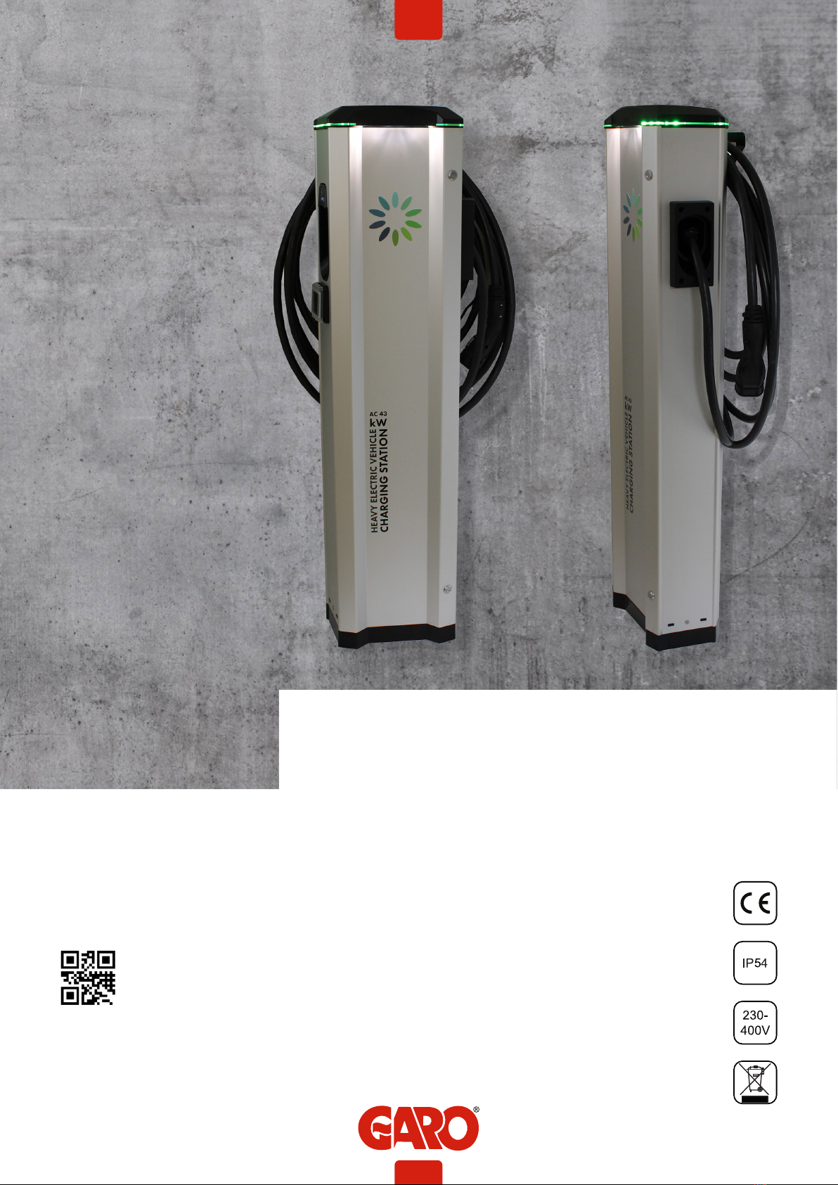
GARO LS4 is an EVSE station for Mode-3 AC charging up to
43kW.
Below are some example of standard features:
• Fixed cable for Mode-3 EV charging.
• Suitable for installation on ground.
• LED status indication.
• Upgradeable firmware*
• Visible energymeter
• OCPP via 4G or LAN*
• RFID reader for secure authorization (not activated as default)*
LS4 supports following features:
• External DLM energy meter*
• Cluster installation of multiple LS4 via Ethernet*
• Cluster installation of multiple LS4 MINI, LS4 and GLB+ via
Ethernet*
* Require certified technician
SAFETY INFORMATION
The LS4 stations are designed exclusively for charging
electric vehicles.
All installation must be carried out by an authorized
installer and comply with local country installation
regulations. If any questions, please contact your local
electrical authority.
Refer to local standards and regulations not to exceed
charging current limitations.
To even out the load, it is important to rotate the phases
when connecting several of LS4 stations to the same
system. Note that 1-phase charging is common in electric
vehicles and L1 (left side) and L2 (right side) in the LS4 is
used for this purpose.
Ventilation signal from EV is not supported. This means that
test of “State D” is not possible.
Adapters for charging connectors are not allowed to be
used.
Cord extension sets for charging cable is not allowed to
be used.
Do not use private power generators as a power source
for charging.
Incorrect installation and testing of the LS4 stations could
potentially damage either the vehicles battery and/or the
LS4 itself.
Do not operate the LS4 stations in temperatures outside its
operating range – see technical specifications.
INFORMATION
3
EN

Each LS4 station is pre-programmed from factory and
tested according to the specification from customer. There
is no need for any programming or setup by installer
during installation.
Plan the installation site carefully so that the risk of being
hit by vehicles is minimized.
Each LS4 station is individually marked with a unique
“M-number” so that the installer can identify each LS4
station. The M-number label is located at upper right
hand side corner behind the front door. When contacting
GARO support, please have the M-number available.
LS4 stations that are pre-configurated for backend-
solution have the ChargeBoxID (CBID) labeled under the
M-number label.
GENERAL INFORMATION
Manual
LS4
Keys
Cable holder
2 x
INFORMATION
CONTENT
Incorrect installation and testing of the LS4 could
potentially damage either the vehicle and/or the LS4
itself.
Poor quality electricity may harm the LS4 and or the
vehicle. An example of such source of poor quality
electricity may be private power generators.
Do not operate the LS4 in temperatures outside its
operating range – see technical specifications.
CAUTIONS
4
EN

INSTALLATION
1. Mount the LS4 and install the supply cable. See picture
1-5.
Phase-rotation is recommended in order to achieve even
load on all phases when several LS4 stations are installed
to same mains. For example:
1st LS4: L1, L2, L3
2nd LS4: L3, L1, L2
3rd LS4: L2, L3, L1
And so on….
Note: When DLM is pre-configurated from factory, follow
the marked phase order label at incoming terminals. All
pre-configured LS4 contains the information about this
inside the cabinet
The gasket at the bottom of the LS4 need to tighten
properly around the mains cable in order to avoid dirt,
dust, bugs etc to enter the LS4. See picture 4.
Note! The touch protection cover need to fix with
attached screws to ensure proper earth bonding to
the touch protection cover.
2. In cases with LS4 stations connected in a grid, install TP
cable CAT6 with RJ45 connectors between each LS4
station and the provided ethernet router/switch (located
ie. in the LS4 master. Se example of ethernet wiring
diagram picture 6, 7.
In cases with LS4 stations connected in a grid, installation
of the LS4 stations need to follow the installation order in
the attached Master/slave file. See table 1.
3. In cases with external energy meter (for DLM function),
connect the energy meter communication terminals A- and
B+ to LS4 Master station terminals 200 A-) and 201
(B+). The energy-meters modbus adress must be set to
#2. The modbus RS-485 communication settings is: Baud
9600, 8bit, 1 stop bit, no parity
4. Turn on the electric power.
5. Test the LS4 station on both sides with a EVSE-tester or an
EV. In cases where authorization (by RFID tag or similar)
is needed to start charging please contact the backend
administrator.
6. Fill in the warranty form completely.
Example of Master/Slave form for LS4 stations connected in a grid
Role Serialnumber / M-number
Master M00001
Slave 1 M00002
Slave 2 M00003
Slave 3 M00004
Slave 4 M00005
Slave 5
Slave 6
Slave 7
Slave 8
Slave 9
Slave 10
INSTALLATION
5
EN

(picture 1)
(picture 2)
Cu = 2,5Nm Al = 4Nm
OPTION
INSTALLATION
CU/AL
6
EN

0,8Nm +-0,05
(picture 3)
(picture 4)
(picture 5)
INSTALLATION
7
EN

3pcs LS4 connected with TP CAT6 cable to router/switch
5pcs LS4 connected with TP CAT6 cable to router/switch
(picture 6)
(picture 7)
Example of DLM meter installation
Modbus address #2
9600, 8, 1, no parity
Terminals:
#200 - A-
#201 - B+
DLM meter
INSTALLATION
8
EN

Connect the charging cable to the EV.
If authorization is activated, please hold a valid RFID-tag against the RFID reader on the side of the LS4 you want to use or use the
operator app to authorize charging.
Charging will start instant if the EV is ready for charging. See your EV charging manual.
When finishing charging, follow the EV’s instructions.
After charging: Release the charging cable from your EV and place the charging cable at designated place.
Firm
No car connected Charging station available and ready for charging
Car connected State B: Car connected but not yet ready for charging
Car connected State C: Car connected and ready for charging, but charging
station requires authentication to start charging (Free Charging =
"OFF").
Blinking (3 blinks)
When car connects The charging station detects that the cable is connected, but is
yet to detect the car.
Blinking (30
second blink)
Whenever during operation Charging station have received command from backend to start
charging and is waiting for car to connect.
Firm
Car connected Charging is ongoing (state C)
Car connected Charging is paused (state B)
Blinking
Whenever during operation Charging station/point is reserved for a specific user
Firm
Whenever during operation DC fault monitor may be defect.
Whenever during charging Residual Circuit Current Breaker (RCCB) triggered.
Whenever during charging DC fault detected.
Whenever during charging Circuit breaker (MCB) triggered - Overload / short circuit
Whenever during charging Type 2 connector motor locking was released/unlocked (the
cable can be removed)
When connecting car The socket outlet can not engage locking mechanism to lock the
connector.
When connecting car Charging cable is damaged.
Firm (3 seconds)
When RFID is presented RFID card is not valid or not approved by backend.
Blinking
Whenever during operation Charging station/point is deactivated.
Blinking
When RFID is presented Charging station is verifying the RFID in backend cloud service.
LED light indication When Cause of error
USER INSTRUCTIONS
NORMAL USE
9
EN

NO LIGHT
Charging station and internal
meters are powerless.
The upstream circuit breaker have been triggered.
4-pole main circuit breaker inside the bottom of charging station
is deactivated.
Charging station is powerless
(no LED light), but the internal
meters have power.
1-pole main circuit breaker inside the bottom of charging station
is deactivated.
The 12V power supply unit is deactivated (Green LED-light [DC
OK] on 12V supply unit is not lit).
Upper PCB is not receiving power (DC 12V).
The 12V power supply unit has power, but the charging
controller/controllers still do not indicate green on LED-light
[Ready]. When operating normally, the LED-light should show
blinking green.
LED light indication When Cause of error
LED light indication Measure 1 Measure 2
Firm
No error
Have you tried everything
without success? Contact
installer or GARO Support
(please have M-number
available)
Check car settings that can influence charging, i.e gear in
parking mode, doors closed, car locked etc.
Present a valid RFID to the RFID card reader (look for RFID
symbol), start charging via mobile app or contact charging
station operator to start charging remote via backend.
If the charger is supposed to work without RFID/app
authentication, contact the backend operator and ska them to
verify that "Free charging" is set to ON.
Blinking (3 blinks)
Connect the charging cable to the vehicle, or verify that cable is
connected correctly. If no success, try a different charging cable
if available.
Blinking (30
second blink)
Connect the charging cable, or verify that cable is connected
correctly.
Firm
No error Have you tried everything
without success? Contact
installer or GARO Support
(please have M-number
available)
No error
Blinking
No error (contact backend operator if this is not the desired
mode)
USER INSTRUCTIONS
10
EN

Firm
If the orange "alarm" LED indicator on the charge controller is firm
lit, then the charge controller needs to be replaced.
Have you tried everything
without success? Contact
installer or GARO Support
(please have M-number
available)
Firm Red light will always
generate an alarm to the
backend operator.
Reset the RCCB inside the charging station.
Verify that the 8-pole quick connection on the charge controller is
properly connected.
Verify correct grounding and phases in building electrical system
When car is connected: Disconnect charging cable from the
charging station, then the LED indication shall return to GREEN.
Reconect charging cable to start charging. The charging
will restart automatically after 15 minutes if cable is not
disconnected.
Reset circuit breaker.
Check internal wiring and components for possible reasons for
short circuit.
Verify allowed maximum current in backend charger configuration
(OperatorCurrentLimit).
Check motor locking wiring and connection for damages. Verify
that locking mechanism rod and arm are not stuck.
Verify that the connector is properly inserted into the socket. Light
force may be applied.
Verify that there are no foregin objects inside the socket outlet,
hence blocking the connector.
Verify that the motor locking is properly installed and without
visual damages.
Check charging cable and connectors for damages. Test with
another cable if available.
Verify that CP and PP connection pins and wires are not loose or
having bad connection.
Verify grounding of charging station.
Firm (3 seconds)
Verify that the RFID token is approved by backend (contact
backend operator). Have you tried everything
without success? Contact
installer or GARO Support
(please have M-number
available)
Verify that the RFID token is stored in charger internal memory /
whitelist (requires certified technician)
Blinking
Contact backend operator and ask for remote activation.
Blinking
No error
LED light indication Measure 1 Measure 2
USER INSTRUCTIONS
11
EN

LED light indication Measure 1 Measure 2
NO LIGHT
Reset circuit breaker in upstream switchboard.
Have you tried everything
without success? Contact
installer or GARO Support
(please have M-number
available)
Check mainbreaker, reset it if it is deactivated.
Check mainbreaker (1-pole 10A), reset it if it is deactivated.
Verify that 12V power supply unit is receiving 220V AC power
via terminals L & N.
Disconnect red/black cables from the power supply unit terminals
marked "+/-".
If the power supply unit when red/black cables were
disconnected, then it has deteced an earth fault in one of the DC
powered components (controllers, upper PCB, router/switch etc.)
inside the charging station.
If LED-light [DC OK] remains turned off, consider replacing the
12V power supply unit.
Check red/black cable and connection between DC terminal
and upper PCB quick connection (located on far left side of
upper PCB in the charging station).
Verify that the controller has 12 V DC power supplied (4-pole
quick connection on down-side of controller -> terminal 1 & 2
from the left) and that the LED-light [Ready] is blinking green.
If power supply is ok, but no blinking green, then consider
replacing charging controller.
USER INSTRUCTIONS
12
EN

LED light indication Indication / fault code in Web UI OCPP fault code
Firm
IDLE (available) - (A) Vehicle not connected
IDLE (available) - (B) Vehicle connected not ready
IDLE (available) - (C) Vehicle connected ready
Blinking (3 blinks)
IDLE (available) - (A) Vehicle not connected
Blinking (30
second blink)
AUTHORIZED (available) - (A) Vehicle not connected
Firm
CHARGING (occupied) - (C) Vehicle connected ready
CHARGING (suspendedEV) - (B) Vehicle connected not ready
Blinking
Reserved
Firm
RCD triggered groundFailure
Residual current detected via sensor groundFailure
MCB of type 2 socket triggered overCurrentFailure
Actuator unlocked while charging connectorLockFailure
Plug locking failed connectorLockFailure
Possible CP and PR wiring issue. otherError
Blinking
UNAVAILABLE (unavailable) Unavailable
USER INSTRUCTIONS
1400
300
206
368
500
13
EN

XD1
PE
N
L1
L2
L3
RFID 1
EB1
100W
Ant.
+
-
DC Terminal
AC Terminal = AC Terminal Block 230V
T1 = Powersupply 12V/230V
K3 = Contactor for Heater Cold Option
RFID 1 = RFID Reader
KF1 = Led light Topcard
ANT = 4G antenna
Components Placement (Read from top to bottom)
CC1 = Charge Controller (Master)
P1 = Energymeter
XD1 = Type2 Charging Cable
DC Terminal = DC Terminal Block +12V/-12V
XN1= Neutral Terminal Block
QA1 = Contactor
XPE1= Protection Earth Terminal Block 1
XPE2= Protection Earth Terminal Block 2
CT1 = Current transformer 100A
CT2 = Current transformer 100A
CT3 = Current transformer 100A
FC3 = Fuse Charge Controller and Powersupply
FC1 = Fuse
FB1 = RCCB
200/201 = External Meter TerminalBlock 200/201
Q1 = Main Breaker
SP1 = Surge Protection
EB1 = Heater Cold Option
X1 = Incoming Terminal Block
X1
CC1
-QA1
XN1
230V
12V
T1
K3
AC Terminal
CT1 CT2 CT3
P1
-XD1
XPE1
XPE2
FB1FC1
0
1
201
200
FC3
SP1Q1
-KF1
ELECTRICAL DIAGRAM
ELECTRICAL DIAGRAM
14
EN

PE NL3 L2 L1
-X1 Incoming Terminal Block
I
125A
Q1
6
5
8N
7N
2
1
4
3
LN
SP1
RYGGPLÅT
DC Terminal (-)
CC1-PE
I
63A D
-FC1
5
6
7
8
1
2
3
4
5 N
-FB1
63A B
6 N4 2
3 1
mA
30
10A
-FC3
I
2
1
5
6
3
4
7
8
-QA1
1
2
CP
L1
L2
L3
PE
N
Type 2
Charging cable
63A
CC1-CP
S1 S2
S1 S2
S1 S2
10 11 12 13 14 15
16 17
4 5 678 9
N 1 32
CT1
CT2
CT3
CT1 CT2 CT3
-XPE2
-XPE1
-P1
CC1-A MOD
CC1-B MOD
AC Terminal
35
Feritte
525 Ohm
DOUBLE
INSULATED
CABLE
16
1,5
-XN1
L
N
-EB1 Heater Cold Option
10A
-FC3
I
2
1
P1-11
P1-11
XD1-CP
201
200
External Energy Meter
A1
A2
-QA1
-XPE2
-XN1
-AC Terminal
3
4
1
2
-K3
+ -
230V
12V DC
LN
-T1
0V
12V
-DC Terminal
B2 Modbus
A2 Modbus
GND2 Modbus
RJ45
246 8
5 71 3
Opto1 In-
Opto1 In+
ArotoMBrotoM
Motor HS1
Relais 13
Motor HS2
Relais 14
CC1 Down Side
WA
Relais 23
WA
Relais 24
CT
Eth 1
10/100
CC1 Up side
0V
12V
PE
PE
1A 1B
CP
PP
-CT4
ELECTRICAL DIAGRAM
15
EN

RFID 1
2468
5 71 3
Opto1 In-
Opto1 In+
ArotoMBrotoM
Motor HS1
Relais 13
Motor HS2
Relais 14
GND2 Modbus
B2 Modbus
A2 Modbus
WA
Relais 23
WA
Relais 24
RJ45
CC1 Down Side
0V
12V
-DC Terminal
A1
A2
-K3
+-
OUT IN
OUT IN
-++-
-++-
CC RFID
12V
+
GND
HEAT
Top Card
-KF1
R17
R18
R19
R20
Ferrite
320 Ohm
ELECTRICAL DIAGRAM
16
EN

TECHNICAL SPECIFICATIONS
Product type LS4 43kW
Standards / Directives IEC 61851-1 and IEC 61439-7
EMC Classification: 2014/30/EU
Installation method: Ground
Installation environment: Indoor / Outdoor
Location type: Non-restricted Access
Rated Voltage: 3-phase 400VAC 50Hz
Rated Current (configurable) 63A, 32A 1-phase or 3-phase
Installation systems: TT, TN and IT* systems
Charging type: Mode 3
Charging method AC Charging
Protection class: IP54
Mechanical impact resistance: IK10
Temperature range: -25C - +40C
Weight: 40kg
Standard cable length (fixed cable version): Standard 7.5m
Rated current withstand 10kA
Rated short-time withstand current 10kA
Rated conditional short-circuit current of an assembly 10kA
Short-circuit protective device type Type C
Rated impulse withstand voltage 4kV
Rated insulation voltage 230/400V
Rated current of each circuit 63A
Rated diversity factor RDF=1
Pollution degree: 3
EMC environmental condition A and B
RFID Frequency Band 13.56MHz
RFID output power 250mW
SERVICE INFORMATION
Care and maintenance GARO charging station LS4:
The warranty will only remain valid if service is performed.
Service is performed once a year and must be documented.
General authorization EL is required to perform service, i.e. only a
qualified electrical contractor should perform the
service. The service is performed by inspecting the charging
station’s exterior and interior parts, manipulating
components and conducting a functional inspection.
If the charging station is connected to a web portal or otherwise
controlled from an external system via a service
provider, the service personnel must contact the service provider
before a scheduled service. This is to be able to carry
out all steps in the service, but also to avoid automatic error
reports being sent from the charging station when service
starts that may lead to other service personnel being called out at
great expense. Normally the instructions for the
charging station indicate whether it is connected to a superior
service.
If you have questions about service or a need for service, please
contact your GARO retailer.
TECHNICAL SPECIFICATIONS
17
EN

FORM FOR ANNUAL SERVICE AND MAINTENANCE
Check point for annual service and maintenence: Status/Value Comment/remark
Visual check outside cabinet
LED indication lit
Check cables, connectors, connector pins
Check color, foil and instructions
Check external antenna (when installed)
Check fastening to ground
Cean LS4 outside surface
Check locking mechanism
Check both RCCB by pressing “T” button. Check that LED
indication switches to red color for both sides
Function test by appropriate EVSE test instrument
Check RFID reader (when available). Indication by 2 or 3
flashes from LED:s
Turn off the electrical power
Check gaskets
Check torque for mains terminals
Check torque for LS4 fixing screws towards ground/wall
Check torque on standard components and contactors
Check torque for connectors on contactors, relays,
energymeters and DC-PSU
Check connectors on CCU module
Check charging cable’s strain relief, and that the
charging cable cannot be rotated in the strain relief.
Tighten if necessary.
Open the Type 2 connector and check the tightening
torque 2.5Nm.
Measure the earthing resistans (Ohm) on EV sockets/cables
with a multimeter
Clean inside when necessary
Turn on the electrical power
Check charging function on both sides
Plant ID: Name: Date:
ANNUAL SERVICE AND MAINTENANCE
18
EN

WARRANTY CONDITIONS
1. The product benefits from manufacturer´s warranty. The applicable warranty period must be
stated in purchase documents from your supplier.
2. The product must be installed by a certified installer / contractor.
3. Proper installation, storage and operation conditions must be obtained.
4. Warranties apply only to products installed in their original installation location.
5. Installation, use, care, and maintenance must be normal and in accordance with instructions.
6. Warranty requires a dated, fully filled in Warranty form by an certified installer/contractor. If
the original installation date cannot be verified, then the warranty period begins ninety (90)
days from the date of product manufacture (as indicated by the model and serial number).
7. Warranty does not cover damage occurred by incorrect use of equipment, use of any non-
original spare parts, lack of maintenance or faults caused by disassembly of the product or
unauthorized persons intervention,
8. Warranty does not cover software or update thereof.
9. Warranty does not cover aesthetic deficiencies caused by negligent manipulation or
accidents (breaks or damage to the carcass).
10. Warranty does not cover damage caused by external overvoltage from either grid or car/
charging object.
11. Warranty does not cover damage caused by force major like for example but not limited
to: floods, winds, fires, lightning, accidents, sabotage, military conflicts, terrorism, volcanos,
earthquakes or corrosive environments.
Sverige/Sweden
Garantivillkor enl ALEM 09.
OBS! Fullständigt ifylld garantiblankett krävs.
Garantin gäller ej om produkten varit utsatt för ett isolationstest, sk meggning.
EU Countries (except Sweden)
WARRANTY CONDITIONS
19
EN

WARRANTY FORM / GARANTIFORMULÄR
LS4 Model: M no:
Electrical installation data
Group fuse (A):
Supply cable dimension:
Function Test
Testbox / EV (model)
Date:
Sign Installer:
Company Name:
Owner / Customer Name:
Installation adress:
WARRANTY FORM
20
EN
Table of contents
Other GARO Batteries Charger manuals

GARO
GARO Wallbox GLB User manual

GARO
GARO ATLE User manual

GARO
GARO Wallbox GHL User manual

GARO
GARO GHL User manual

GARO
GARO QC45 User manual

GARO
GARO Twinbox GTB User manual

GARO
GARO GLB****-B series Installation instructions

GARO
GARO GLB User manual

GARO
GARO LS4 Wallmounted User manual

GARO
GARO Castra CLS1 User manual
Popular Batteries Charger manuals by other brands

AEG
AEG PROTECT RCS Operation manual

AIMS Power
AIMS Power Global LF Series user manual

La Crosse Technology
La Crosse Technology BC-900 instruction manual

Schumacher
Schumacher SC1339 owner's manual

Circontrol
Circontrol Post eVolve Series installation manual

VOLTCRAFT
VOLTCRAFT V-CHARGE ECO Quad Lipo operating instructions