GARO Wallbox GLB User manual

GARO Wallbox GLB
Quickstart guide stand-alone GLB Wallbox
manual 380226-1.0
EN

1
EN
Warnings
When Dielectric Voltage Withstand Test is done on an installation, it is important to disconnect the
terminal J1 on the GLB main board.
This equipment should not be used by anyone (including children) with reduced physical, sensory
or mental capacity, or anyone lacking in experience or knowledge, unless they are provided with
supervision or prior instruction in how to use the equipment by the person responsible for their safety.
The GLB Wallbox range of charging stations is designed exclusively for charging electric vehicles.
The GLB Wallbox must be grounded according to local country installation requirements.
Do not install or use the GLB Wallbox near flammable, explosive, harsh, or combustible materials,
chemicals, or vapors.
Turn off the electrical power at the circuit breaker before installing, configuring or cleaning of the GLB
Wallbox.
Use the GLB Wallbox only within the specified parameters.
Never spray water or any other liquid directly at the GLB Wallbox. Never spray any liquid onto
the charge handle or submerge the charge handle in liquid. Store the charge handle in the dock to
prevent unnecessary exposure to contamination or moisture.
Do not use this equipment if it appears to be damaged or if the charging cable appears to be
damaged.
Do not modify the equipment installation or any part of the product.
Do not touch the GLB Wallbox’s end terminals with fingers or any other objects.
Do not insert foreign objects into any part of the GLB Wallbox.
TABLE OF CONTENTS
Warnings 1
Cautions 2
Notes 2
Installation of standalone GLB Wallbox 3
Normal Use/Charging 4
Basic LED indications 5
Software GLB 5
Service/Maintenance 5
Troubleshooting/Support/FAQ mm 5
Technical specifications 5
Installation sketch 6
Warranty form 10
Warranty conditions 11

2
EN
Cautions
Do not use private power generators as a power source for charging.
Incorrect installation and testing of the GLB Wallbox could potentially damage either the vehicle’s
battery and/or the GLB Wallbox itself.
Do not operate the GLB Wallbox in temperatures outside its operating range – see technical
specificatrions.
Notes
All installation must be carried out by an authorised installer and comply with local installation
regulations. If any questions, please contact your local electrical authority.
Ensure that the GLB Wallbox’s charging cable is positioned so it will not be stepped on, driven over,
tripped on, or subjected to damage or stress.
Unroll the charging cable to prevent it from overheating.
Do not use cleaning solvents to clean any of the GLB Wallbox’s components. The outside of the GLB
Wallbox, the charging cable, and the end of the charging cable should be periodically wiped with
a clean, dry cloth to remove accumulation of dirt and dust.
Be careful not to damage the circuit boards or components during installation.
Refer to local standards and regulations not to exceed charging current limitations.
The front cover must always be locked in its upper position in order to ensure compliance with IP
Code IP44.
Avoid to install the GLB Wallbox in direct sunlight to avoid any heat-problems.
To even out the load, it is important to rotate the phases when connecting several of GLB Wallboxes
to the same system. Note that 1-phase charging is common in electric vehicles and L1 in the GLB is
used for this purpose.
Ventilation signal from EV is not supported.
Adapters for charging connectors are not allowed to be used.
Cord extension sets for charging cable is not allowed to be used.

3
EN
(for installation of GLB in cluster, see User manual at www.garoemobility.com/support)
INSTALLATION OF STANDALONE GLB WALLBOX
1) GLB Wallbox without RCCB or RCBO included in the enclosure must have Residual Current
protection and must be protected with a max 32A fuse in the supply distribution box.
2) GLB Wallbox without RCCB Type B fitted or DC fault protection in the enclosure must in
accordance to IEC 60364-7-722 be protected with a Residual Current Device (RCD) Type B.
3) 3-phase GLB Wallbox equipped with a Residual Current Circuit Breaker (RCCB) must be
protected with a max 32A fuse in the supply distribution box.
4) 1-phase GLB Wallbox fitted with a Residual Current Breaker with Overcurrent Protection
(RCBO) can be connected in parallel. This group of chargers must be protected by a backup
fuse in the distribution box. The backup fuse shall not exceed 125A.
GLBDC..-..22..-A 3)
1-phase
3-phase
No RCBO or RCCB
RCBO
RCCB type A
DC-fault protection
RCCB type B
GLB Type
GLB..-..37.. 2) 4)
GLB..-..74.. 2) 4)
GLB..-..22.. 1) 2)
GLB..-..22..-A 2) 3)
GLB..-..22..-B 3)
GLBDC..-..37.. 4)
GLBDC..-..74.. 4)
GLBDC..-..11.. 1)
GLBDC..-..22.. 1)
Protection type

4
EN
Normal Use/Charging
Connect the charging cable to the EV. Charging will start instant if the EV is ready for charging. See
your EV charging manual.
When finishing charging, follow the car’s instructions.
After charging: Release the charging cable from your EV and place the charging cable at designated
place.
1. Select the appropriate group fuse (1x6A - 3x32A) and cable area for the electrical
installation. Some countries require earth fault breakers to be installed. Follow local country
regulations and select the appropriate earth fault equipment for the electrical installation.
NOTE! Due to high currents for a long time in the cable, there is a high risk of voltage drop if
the cable is under-dimensioned which can damage the electronics in an EV.
2. Fill in the information in the Warranty form.
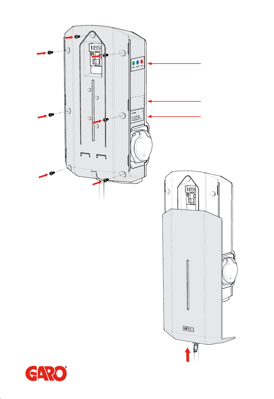
3. Mount the GLB Wallbox according to the installation sketch, (figure 1-5)
4. Set dip switch SW1 to same (A) as the main fuse (16-63A). SW1 is located at the center left
hand side of the main board. See figure 9.
5. Set the dip switch SW2 according to your group fuse for the GLB Wallbox ( 6-32A). Dip
switch 2 is located at bottom left corner of the main board. See figure 9.
6. Install the electrical power supply cable according to local regulations.
7. Fill in serial number in the Warranty form. See QR code label at upper right corner of the
main board.
8. Mount the box cover on the enclosure + front lid, see figure 7-8.
9. Turn on the electrical power to the GLB Wallbox.
10. For GLBW… and GLBDCW… models: Connect a mobile device (PC/Tablet/Mobile) to
the GLB Wallbox Wifi network. You find SSID and password on the rating label. Type in
172.24.1.1 in your web browser and check that the GLB webinterface is visible. This action
confirms that the GLB Wallbox communication module is working properly.
11. Test the charger with a test instrument or test to charge an electric vehicle to ensure that the
charger is working properly.
12. Doublecheck that the Warranty Form is filled in completely, sign with name, date and
company that the warranty is valid.

5
EN
Technical specifications
Product type: all GLB models
Standards/directives: IEC 61851-1 and IEC TS 61439-7
Installation: Wall mounted
Voltage rating: 230V/400V 50Hz
Installation systems: TT-, TN- and IT systems
Charging mode: Mode 3
Charging method: AC charging
Protection class: IP44
Mechanical impact resistance: IK08
Temperature range: -250C – +400C (without direct sunlight)
Recommended installation height: 0.5–1.5 metres above ground
Weight: 3-5,4 kg depending on model
Standard cable length (when
included):
5 m
Software GLB
See User manual at www.garoemobility.com/support
Service/Maintenance
See User manual at www.garoemobility.com/support
Troubleshooting/Support/FAQ mm
See User manual at www.garoemobility.com/support
Basic LED indications
Solid green light: ready for charging
Flashing green light: GLB Wallbox waiting for start signal from electric vehicle
Shifting blue light intensity: charging
Other LED indications: see User manual at www.garoemobility.com/support

(figure 3)
(figure 1)
(figure 2)
(7 x T20)
Installation sketch

TERMINAL BLOCK L3 N PEL2L1
L N PE
L3 N PEL2L1
3-phase
1-phase
Serial no./SSID password
Drill template
(see the back of the box)
(figure 4)
(figure 5)
(figure 6)

language label is
placed on the side
(7 x T20)
label explaining charger
status indication
english information label
(figure 7)
(figure 8)

(figure 9)
ON OFF
SW2
Main fuse 16A 20A 25A 32A 40A 50A 63A
SW1(DIP 1-3) 16A 20A 25A 32A 40A 50A 63A
SW2(DIP 1-3) 13A 16A 20A 25A 32A 32A 32A
(figure 10)
(figure 11)

SW2
1
2
3
4
5
6
1
2
3
4
GLB Model:___________________________________
Electrical installation data / Elektrisk installation information
Group fuse (A)
Gruppsäkring (A)____________________________________________________________
Supply cable dimension:
Area matningskabel:_________________________________________________________
Cable length:
Längd matningskabel:________________________________________________________
Option Modules / Options-moduler
RFID yes/no:
RFID ja/nej:________________________________________________________________
Communication Module yes/no:
Kommunikationsmodul ja/nej:_________________________________________________
Settings / Inställningar
Mark existing positions:
Markera nuvarande inställningar:
Software version:
Mjukvaruversion:____________________________________________________________
Function Test / Funktionstest
Testbox / EV (model)
Testlåda / EV (modell)________________________________________________________
Sign Installer:
Signatur installatör: __________________________________________________________
Company Name:
Företagsnamn:______________________________________________________________
Ownwer / Customer Name:
Ägare / kundens namn_______________________________________________________
Warranty form/Garantiblankett
(figure 11)

1. The product benefits from warranty, Technical support and free service for a period of 60
months from the date of installation / commissioning, Thus undergoing repair or (if not
possible) free replacement of any parts that have manufacturing defects. The deadline for
resolving the non-compliance is 60 days.
2. The product must be installed by a certified installer / contractor.
3. Proper installation, storage and operation conditions must be obtained.
4. Warranties apply only to products installed in their original installation location.
5. Installation, use, care, and maintenance must be normal and in accordance with instructions.
6. Warranty requires a dated, fully filled in Warranty form by an certified installer/contractor. If
the original installation date cannot be verified, then the warranty period begins ninety (90)
days from the date of product manufacture (as indicated by the model and serial number).
7. Warranty does not cover damage occurred by incorrect use of equipment, use of any non-
original spare parts, lack of maintenance or faults caused by disassembly of the product or
unauthorized persons intervention,
8. Warranty does not cover aesthetic deficiencies caused by negligent manipulation or
accidents (breaks or damage to the carcass).
9. Warranty does not cover damage caused by external overvoltage from either grid or car/
charging object.
10. Warranty does not cover damage caused by force major like for example but not limited
to: floods, winds, fires, lightning, accidents, sabotage, military conflicts, terrorism, volcanos,
earthquakes or corrosive environments.
Sverige/Sweden
Garantivillkor enl ALEM 09.
OBS! Fullständigt ifylld garantiblankett krävs.
Garantin gäller ej om produkten varit utsatt för ett isolationstest, sk meggning.
Warranty conditions
EU Countries (except Sweden)

GARO AB
Box 203, SE–335 25 Gnosjö
Phone: +46 (0) 370 33 28 00
Fax: +46 (0) 370 33 28 50
garo.se
Other manuals for Wallbox GLB
2
This manual suits for next models
1
Table of contents
Other GARO Batteries Charger manuals

GARO
GARO Wallbox GHL User manual

GARO
GARO Wallbox GLB Series User manual

GARO
GARO GLB****-B series Installation instructions

GARO
GARO ENTITY PRO Owner's manual

GARO
GARO Wallbox GLB+ User manual

GARO
GARO Castra User manual

GARO
GARO Twinbox GTB Series User manual

GARO
GARO QC45 User manual

GARO
GARO TWIN User manual
Popular Batteries Charger manuals by other brands

ChargePoint
ChargePoint CPF25 installation guide

Honeywell
Honeywell 057530.10 Mounting and Connection Instructions

FiT
FiT FIT STANDARD CHARGER 36V instruction manual

Mec
Mec NOVA-650F Series instruction manual

PC Treasures
PC Treasures ChargeIt! user manual

Rothenberger
Rothenberger ROCAM 4 Instructions for use