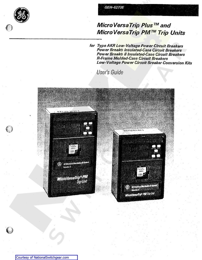
GE AK-1-50 User manual

Micro
Versa
Trip
Plus
and
MicroVersaTrip
PM
Conversion
Kits
For
GE
Types
AK
-
1
-
50
Low
-
Voltage
Power
Circuit
Breakers
INTRODUCTION
GE
Conversion
Kits
are
designed
to
upgrade
existing
GE
Low
Volt
-
age
Power
Circuit
Breakers
,
rather
than
replacing
the
entire
breaker
.
The
Conversion
Kits
contain
enhanced
solid
-
state
MicroVersaTrip
Plus
or
MicroVersaTrip
PM
Trip
Units
,
representing
the
latest
techno
-
logical
advancement
in
GE
trip
systems
.
MicroVersaTrip
Plus
and
MicroVersaTrip
PM
Conversion
Kits
are
des
-
igned
and
breaker
tested
to
conform
with
ANSI
Standard
C
37.59
,
allowing
the
retrofitter
to
properly
install
and
acceptance
test
’
the
breaker
.
This
publication
covers
installa
-
tion
of
MicroVersaTrip
Plus
and
PM
Conversion
Kits
on
GE
Types
AK
-
1
-
50
Low
Voltage
Power
Cir
-
cuit
Breakers
.
EacfvConversion
Kit
contains
all
appropriate
mate
-
rial
to
convert
from
an
existing
GE
Type
ECFjxip
system
.
Courtesy of NationalSwitchgear.com

TABLE
OF
CONTENTS
«
SECTION
1
GENERAL
INFORMATION
3
SECTION
2
PRIOR
TO
INSTALLATION
3
SECTION
3
FRONT
AND
BACK
FRAME
DISASSEMBLY
AK
-
50
Frame
Separation
4
4
SECTION
4
BACK
FRAME
BREAKER
CONVERSION
Electromechanical
Trip
Device
Removal
.
.
.
Installing
the
Phase
Sensors
(
CT
’
s
)
5
5
5
-
6
SECTION
5
FRONT
FRAME
BREAKER
CONVERSION
Flux
Shifter
Installation
Programmer
Mounting
Bracket
Installation
.
Trip
Paddle
Installation
7
7
8
9
SECTION
6
BREAKER
ASSEMBLY
Frame
Assembly
Wire
Harness
Installation
Flux
Shifter
Adjustment
Programmable
Trip
Unit
Installation
10
10
10
11
11
SECTION
7
FOUR
-
WIRE
GROUND
FAULT
OPTION
Installing
the
Neutral
Sensor
12
12
13
-
15
SECTION
8
TESTING
AND
TROUBLESHOOTING
2
Courtesy of NationalSwitchgear.com

Preparatory
to
the
conversion
,
the
installer
should
verify
that
the
appropriate
current
sensors
and
programmer
unit
have
been
furnished
.
Whenever
the
ground
fault
trip
element
is
fur
-
nished
for
breakers
applied
on
4
-
wire
systems
,
note
that
an
associated
neutral
sensor
(
CT
)
is
re
-
quired
for
separate
mounting
in
the
equipment
.
Make
sure
that
retrofitted
breakers
are
applied
within
their
short
circuit
rating
.
For
example
,
when
the
trip
elements
of
the
breaker
are
to
be
changed
from
long
-
time
instantaneous
to
long
-
time
,
short
-
time
,
the
short
-
time
rating
would
gov
-
ern
the
application
.
As
a
service
-
related
consider
-
ation
,
the
installation
of
the
MicroVersaTrip
Plus
or
MicroVersaTrip
PM
kits
provides
an
excellent
opportunity
to
perform
normal
mainte
-
nance
on
the
breaker
,
particularly
when
the
front
and
back
frames
are
separated
.
Such
procedures
are
described
in
the
installation
and
maintenance
manuals
normally
supplied
with
the
Breakers
and
Equipment
.
SECTION
1
GENERAL
INFORMATION
GE
Conversion
Kit
installation
is
straightforward
,
but
does
require
careful
workmanship
and
atten
-
tion
to
these
instructions
.
Familiarity
with
the
breaker
itself
is
highly
desirable
.
The
general
ap
-
proach
is
to
first
strip
the
breaker
of
its
existing
trip
devices
,
then
install
the
MicroVersaTrip
Plus
or
MicroVersaTrip
PM
kit
components
.
Following
this
procedure
,
the
converted
breaker
is
performance
tested
,
prior
to
restoring
the
breaker
to
service
.
The
majority
of
breaker
kit
installations
do
not
re
-
quire
any
customized
assembly
work
.
However
,
some
conversions
may
involve
unusual
mounting
circumstances
or
accessory
combinations
which
necessitate
minor
modification
and
/
or
relocation
of
a
component
(
s
)
.
In
most
instances
this
supple
-
mentary
work
can
be
done
on
site
.
SECTION
2
PRIOR
TO
INSTALLATION
•
Turn
off
and
lock
out
the
power
source
feed
-
ing
the
breaker
prior
to
attempting
any
installation
,
maintenance
,
or
modification
.
Follow
all
lockout
and
tagging
rules
of
the
National
Electrical
Code
and
all
other
applicable
codes
.
•
Do
not
work
on
a
closed
breaker
or
a
breaker
with
the
closing
springs
charged
.
Trip
OPEN
the
breaker
and
be
sure
the
stored
energy
springs
are
discharged
avoiding
the
possibility
that
the
breakers
may
trip
OPEN
or
the
charg
-
ing
springs
discharge
,
causing
injuries
.
•
For
both
stationary
and
draw
out
breakers
,
trip
OPEN
,
then
remove
the
breaker
to
a
well
lighted
work
area
before
beginning
work
.
•
Do
not
perform
any
maintenance
including
breaker
charging
,
closing
,
tripping
,
or
any
other
function
which
could
cause
significant
movement
of
the
breaker
while
it
is
on
the
draw
out
extension
rails
.
•
Do
not
leave
the
breaker
in
an
intermediate
position
in
the
switchgear
compartment
.
Al
-
ways
leave
it
in
the
CONNECTED
,
TEST
,
or
DISCONNECTED
position
.
Failure
to
do
so
could
lead
to
improper
positioning
of
the
breaker
and
flashback
.
Before
starting
any
work
,
turn
off
and
lock
out
all
power
sources
leading
to
the
breaker
(
primary
and
secondary
)
.
Remove
the
breaker
to
a
clean
,
well
lighted
work
area
.
WARNING
:
Low
Voltage
Power
Circuit
Break
-
ers
utilize
high
speed
,
stored
energy
spring
operating
mechanisms
.
The
breakers
and
their
enclosures
contain
interlocks
and
safety
features
intended
to
provide
safe
,
proper
op
-
erating
sequences
.
For
maximum
personnel
protection
associated
with
installation
,
opera
-
tion
,
and
maintenance
of
these
breakers
the
following
procedures
must
be
followed
.
Fail
-
ure
to
follow
these
procedures
may
result
in
personal
injury
or
property
damage
.
•
Only
qualified
persons
,
as
defined
in
the
Na
-
tional
Electrical
Code
,
who
are
familiar
with
the
installation
and
maintenance
of
low
volt
-
age
power
circuit
breakers
,
and
switchgear
as
-
semblies
,
should
perform
any
work
associated
with
these
breakers
.
•
Completely
read
and
understand
all
instructions
before
attempting
any
breaker
installation
,
operation
,
maintenance
,
or
modification
.
Courtesy of NationalSwitchgear.com

SECTION
3
FRONT
AND
BACK
FRAME
DISASSEMBLY
!
'
w
The
conversion
of
a
GE
AK
-
1
-
50
breaker
requires
that
the
front
and
back
frames
be
disassembled
before
the
kit
can
be
installed
.
Follow
these
steps
to
disassemble
the
breaker
.
I
i
AK
-
50
Frame
Separation
Step
1
Remove
the
(
2
)
breaker
opening
springs
.
Save
them
to
be
re
-
installed
(
Fig
.
1
)
.
Step
2
Remove
the
crossbar
mechanism
pin
by
first
re
-
moving
the
external
retaining
clip
(
Fig
.
2
)
.
Save
the
pin
and
clip
.
Step
3
Remove
and
save
the
(
4
)
or
(
6
)
nuts
and
lock
washers
holding
the
front
and
back
frames
to
-
gether
.
Fig
.
3
shows
an
example
of
one
of
the
nuts
.
Four
nuts
are
used
on
manually
operated
breakers
and
six
on
electrically
operated
breakers
.
Step
4
OPENING
SPRINGS
Fig
.
1
.
AK
-
1
-
50
Circuit
Breaker
Carefully
separate
the
two
frame
halves
.
Fig
.
3
.
Frame
Mounting
Bolts
Courtesy of NationalSwitchgear.com

SECTION
4
BACK
FRAME
BREAKER
CONVERSION
Electromechanical
Trip
Device
Removal
Step
1
Remove
and
discard
the
(
2
)
screws
at
the
base
of
each
trip
device
.
Discard
the
“
C
”
shaped
metal
mounting
bracket
(
Fig
.
4
)
.
Step
2
Remove
and
discard
the
small
phillips
head
screw
at
the
top
of
each
trip
device
(
Fig
.
4
)
.
Step
3
Remove
and
discard
the
(
4
)
Yie
alien
head
bolts
fastening
each
trip
coil
.
The
trip
device
can
be
re
-
moved
and
discarded
(
Fig
.
5
)
.
Installing
the
Phase
Sensors
(
CT
’
s
)
Step
1
Mount
the
new
copper
CT
post
to
the
back
frame
using
the
(
2
)
%
-
16
x
llA
bolts
with
plain
and
lock
washers
provided
(
Fig
.
6
)
.
ALLEN
I
1
LAI
)
BOLLS
PHILLIPS
HEM
)
SCREW
#
BRACKET
Fig
.
4
.
EC
Trip
Device
Removal
NOTE
:
Occasionally
,
during
current
sensor
manufacturing
,
a
slight
separation
may
occur
between
the
epoxy
and
plastic
shell
.
This
may
amount
to
as
much
as
0.030
"
and
has
no
effect
on
performance
.
Additionally
,
slight
surface
imperfections
are
part
of
the
epoxy
curing
process
and
have
no
effect
on
performance
.
x
.
16
BOLTS
(
T
POST
Fig
.
6
.
CT
Post
Assembly
.
p
Courtesy of NationalSwitchgear.com

SECTION
4
BACK
FRAME
BREAKER
CONVERSION
Installing
the
Phase
Sensors
(
CT
’
s
)
(
Cont
’
d
)
Step
2
Fasten
the
(
3
)
small
insulated
wire
fasteners
to
the
back
frame
using
the
(
3
)
54
-
20
x
l
3
/
4
screws
with
plain
and
lock
washers
provided
.
One
fas
-
tener
is
mounted
under
each
CT
(
Fig
.
7
)
.
Step
3
Place
each
CT
over
the
copper
CT
posts
using
a
small
amount
of
RTV
or
an
equivalent
adhesive
to
prevent
the
CT
’
s
from
rotating
(
Fig
.
8
)
.
Step
4
Mount
the
top
copper
bus
over
each
CT
Using
the
!
4
-
13
x
114
alien
head
screw
with
a
plain
and
lock
washer
provided
(
Fig
.
8
)
.
Step
5
Insert
the
(
2
)
%
-
16
x
114
bolts
with
plain
and
lock
washers
provided
through
the
top
copper
bus
,
into
the
contact
arm
assembly
(
Fig
.
8
)
.
Step
6
Tighten
the
%
-
16
bolts
to
200
in
-
lbs
.
and
the
54
-
13
bolts
to
300
in
-
lbs
.
*
(
Fig
.
9
)
.
14
-
20
SCREW
WIRE
FASTENERS
Fig
.
7
.
Wire
Fastener
Installation
*
IMPORTANT
NOTE
:
Steps
designated
by
an
(
*
)
are
critical
electrical
integrity
connec
-
tions
.
They
must
be
correctly
tightened
for
proper
operation
.
Failure
to
tighten
prop
-
erly
will
cause
a
breaker
failure
resulting
in
property
damage
or
personal
injury
.
Fig
.
8
.
CT
Assembly
(
left
to
right
)
%
-
lb
BOLTS
fc
-
13
BOLTS
Fig
.
9
.
Electrical
Contact
Torques
Courtesy of NationalSwitchgear.com

SECTION
5
FRONT
FRAME
BREAKER
CONVERSION
Flux
Shifter
Installation
Step
1
Remove
and
discard
the
(
3
)
trip
paddles
on
the
common
trip
actuator
bar
(
Fig
.
10
)
.
Step
2
Install
the
flux
shifter
mounting
bracket
to
the
left
inside
of
the
front
frame
.
Remove
and
discard
the
grounding
strap
hardware
and
use
the
(
2
)
%
-
16
x
1
bolts
,
%
nuts
and
lock
washers
pro
-
vided
(
Fig
.
11
)
.
Step
3
Bolt
the
flux
shifter
assembly
to
the
bracket
using
the
(
2
)
*
/
4
-
20
x
V
2
bolts
and
lock
washers
provided
(
Fig
.
12
)
.
TRIP
PADDLES
Fig
.
10
.
Trip
Paddle
Removal
FLUX
SHIFTER
BRACKET
X
-
16
BOLTS
Fig
.
11
.
Flux
Shift
Mounting
Bracket
‘
/
«
-
20
BOLTS
FLUX
SHIFTER
Fig
.
12
.
Flux
Shifter
Installation
Courtesy of NationalSwitchgear.com

SECTION
5
FRONT
FRAME
BREAKER
CONVERSION
NOTE
LOCATION
OF
BEVELED
EDGES
ON
PLUG
BODY
4
Programmer
Mounting
Bracket
Installation
Step
1
The
wiring
harness
includes
a
36
-
pin
programmer
connector
which
must
be
pre
-
assembled
to
the
pro
-
grammer
mounting
bracket
.
Follow
step
1
through
5
in
Fig
.
13
to
mount
the
connector
(
Fig
.
14
)
.
Step
2
Fasten
the
programmer
mounting
bracket
to
the
side
of
the
flux
shifter
bracket
using
the
(
2
)
14
-
20
x
V
2
bolts
and
lock
washers
provided
(
Fig
.
15
)
.
ADAPTER
BRACKET
STEP
1
.
PUSH
BRACKET
OVER
NOTCHES
IN
END
OF
PLUG
BODY
v
/
J I
I U
A
r
4
STEP
5
.
HOLD
PLUG
BODY
TIGHT
TO
THE
ADAPTER
BRACKET
AND
BEND
OVER
(
2
)
LOCKING
TABS
CAUTION
:
Adapter
bracket
must
be
installed
onto
harness
plug
as
shown
in
Fig
.
13
.
Failure
to
do
so
will
result
in
harness
plug
failure
and
the
programmer
will
not
provide
protection
.
STEP
3
.
PRESS
ON
PUSH
NUTS
UNTIL
BRACKET
IS
HELD
FIRMLY
AGAINST
PROGRAMMER
BRACKET
O
OJD
A
oooooooo
*
00000000
00000000
oooooooq
,
PIN
1
STEP
4
.
HOLD
PLUG
FIRMLY
BEND
LOCKING
TABS
STEP
2
.
PULL
WIRE
HARNESS
BRACKET
ASSEMBLY
UP
OVER
GUIDE
PINS
AND
PUSH
ALL
THE
WAY
DOWN
4
GUIDE
PINS
>
.
A
a
n
J
]
lir
m
Fig
.
13
.
Harness
Connector
TRIP
UNIT
MOUNTING
BRACKET
K
-
20
BOLTS
Fig
.
14
.
Programmer
Mounting
Bracket
Fig
.
15
.
Programmer
Mounting
Bracket
Installed
8
Courtesy of NationalSwitchgear.com

SECTION
5
FRONT
FRAME
BREAKER
CONVERSION
Trip
Paddle
Installation
Step
1
Assemble
the
trip
paddle
and
the
threaded
back
plate
by
inserting
two
of
the
three
10
-
32
x
%
screws
and
lock
washers
provided
along
the
top
edge
.
Step
2
Slide
the
trip
paddle
over
the
common
trip
actua
-
tor
bar
approximately
1
”
from
the
side
frame
.
Use
the
remaining
10
-
32
x
3
/
i
screw
and
lock
washer
to
fasten
the
trip
paddle
in
place
(
Fig
.
16
)
.
Fig
.
16
.
Trip
Paddle
Installation
9
Courtesy of NationalSwitchgear.com

SECTION
6
BREAKER
ASSEMBLY
t
-
Frame
Assembly
Step
1
Follow
steps
1
-
4
on
page
4
in
reverse
to
reassemble
the
front
and
back
frames
.
IMPORTANT
NOTE
:
Use
extreme
caution
when
joining
the
frames
,
so
that
the
flux
shifter
reset
arm
is
not
damaged
.
The
reset
arm
must
be
assembled
so
that
it
rests
on
the
metal
contact
crossbar
on
the
underside
.
The
arm
will
fit
between
the
left
frame
side
lever
and
the
first
insulated
contact
actuator
lever
.
WIRE
TIES
Fig
.
17
.
Wire
Harness
Installation
Wire
Harness
Installation
Step
1
Connect
the
4
-
pin
flux
shifter
lead
plug
to
the
mating
plug
on
the
wire
harness
and
tie
the
leads
to
the
mounting
bracket
.
Step
2
Bring
the
CT
leads
of
the
wiring
harness
around
to
the
back
and
bottom
of
the
breaker
and
con
-
nect
to
the
CT
’
s
as
shown
in
Fig
.
17
.
Pay
special
attention
to
the
polarity
.
White
-
common
Black
-
tap
Step
3
Tie
the
wire
harness
to
the
insulated
fasteners
un
-
der
each
CT
using
the
wire
ties
provided
.
Make
*
t
certain
that
the
wire
harness
will
not
interfere
with
the
mechanism
of
the
breaker
(
Fig
.
17
)
.
Step
4
Loosen
the
(
2
)
%
-
16
mechanism
bolts
above
the
center
phase
CT
and
insert
the
insulated
barrier
provided
.
Do
not
remove
the
bolts
.
Retighten
the
bolts
,
fastening
the
barrier
in
place
(
Fig
.
18
)
.
Step
5
When
the
communications
portion
of
the
wiring
harness
is
installed
,
it
should
be
tied
to
the
frame
in
a
location
where
it
is
accessible
in
the
switchgear
.
Fig
.
19
shows
a
suggested
location
.
The
actual
location
is
dependent
on
the
configu
-
ration
of
the
equipment
and
may
be
determined
by
a
field
engineer
.
If
the
harness
is
not
used
,
it
may
be
removed
or
coiled
and
tied
to
the
frame
.
Fig
.
18
.
Center
Phase
Barrier
Installation
.
»
Courtesy of NationalSwitchgear.com

SECTION
6
BREAKER
ASSEMBLY
(
CONT
’
D
)
Flux
Shifter
Adjustment
Step
1
Once
the
flux
shifter
and
trip
paddle
are
in
-
stalled
,
the
following
adjustments
must
be
made
:
With
the
breaker
in
the
CLOSED
position
,
the
gap
between
the
trip
paddle
and
the
end
of
the
flux
shifter
adjuster
should
be
Vie
of
an
inch
.
Use
a
!
4
"
wrench
to
adjust
the
screw
.
It
may
help
to
gauge
the
air
gap
with
a
Vie
'
diameter
rod
or
drill
(
not
provided
)
.
The
best
approach
is
to
ad
-
just
the
breaker
in
the
open
position
,
then
check
it
in
the
closed
position
(
Fig
.
20
)
.
ADJUSTMENT
SCREW
TRIP
PADDLE
Fig
.
20
.
Flux
Shifter
Adjustment
IMPORTANT
NOTE
:
Extreme
caution
must
be
used
when
working
on
a
closed
breaker
.
DO
NOT
reach
your
hands
into
the
mecha
-
nism
while
adjusting
the
flux
shifter
.
Step
2
OPTIONAL
TEST
:
The
flux
shifter
assembly
may
be
tested
by
closing
the
breaker
and
applying
a
9
V
dc
power
source
to
the
flux
shifter
leads
.
The
red
wire
is
the
positive
lead
.
The
breaker
should
trip
.
Programmable
Trip
Unit
Installation
Step
1
.
Insert
the
guide
pins
into
the
hole
and
push
on
the
programmer
.
This
will
engage
the
connec
-
tors
and
release
the
locking
lever
which
will
move
in
(
Fig
.
21
)
.
Step
2
.
Verify
that
the
locking
lever
actually
engaged
the
programmer
pin
.
To
remove
the
programmer
,
pull
the
locking
lever
out
,
releasing
the
programmer
pin
.
Then
,
remove
the
programmer
.
£
Fig
.
21
.
Programmer
Installation
11
Courtesy of NationalSwitchgear.com

SECTION
7
FOUR
-
WIRE
Step
3
.
Route
the
wire
through
the
equipment
and
con
-
nect
to
the
2
-
pin
connector
on
the
programmer
harness
.
The
wire
should
be
tied
to
the
breaker
frame
in
an
easily
accessible
location
.
It
may
be
located
with
the
communications
harness
.
See
Fig
.
19
on
page
10
.
GROUND
FAULT
OPTION
i
Installing
the
Neutral
Sensor
The
ground
fault
option
in
all
four
-
wire
systems
an
additional
neutral
sensor
.
The
neutral
requires
sensor
is
installed
in
the
neutral
bus
in
the
equip
-
ment
and
is
connected
to
the
programmable
trip
unit
through
a
wiring
harness
provided
.
Step
1
.
Mount
the
neutral
sensor
on
the
outgoing
neutral
lead
,
normally
in
the
equipment
’
s
bus
or
cable
compartment
(
Fig
.
22
)
.
Step
2
.
Connect
the
neutral
sensor
wire
harness
to
the
correct
taps
on
the
sensor
.
The
tap
setting
on
the
neutral
sensor
must
match
the
phase
sensors
.
Maintain
the
following
color
code
:
White
-
Common
,
Black
-
Tap
I
I
1
LOAD
.
562
DIA
.
HOLES
MAX
.
-
*
STRAP
1.25
M
-
MAX
.
STRAP
3.33
ref
.
1.25
t
r
~
r
|
Tii
iili
!
I
*
*
rh
V
_
i
.
625
l
I
.
625
I
»
I
I
I
4
TERMINAL
BLOCK
1.18
ref
.
*
-
1.75
-
*
*
-
1.75
.
88
i
6.00
i
*
I
T
.
75
e
—
©
-
e
-
e
CGI
T
CGI
3.75
MAX
.
CGI
1.75
3.25
CGI
i
—
T
"
-
©
—
©
-
I
CGI
4
11.25
Fig
.
22
.
Neutral
Sensor
Outline
for
AK
-
1
-
50
Courtesy of NationalSwitchgear.com

SECTION
8
TESTING
AND
TROUBLESHOOTING
WARNING
:
Do
not
change
taps
on
the
current
sensors
or
adjust
the
programmer
trip
unit
set
-
tings
while
the
breaker
is
carrying
current
.
Once
the
breaker
has
been
converted
,
but
before
it
is
energized
,
it
must
be
tested
.
See
below
for
troubleshooting
details
.
TESTING
Before
installing
a
converted
breaker
back
into
service
,
perform
the
following
steps
:
Step
L
Verify
that
the
programmable
trip
unit
is
securely
installed
.
The
phase
sensors
must
not
be
ener
-
gized
if
they
are
open
-
circuited
.
Step
2
.
Megger
the
breaker
primary
circuit
using
a
1
,
000
-
Volt
Megger
.
Step
3
.
Measure
the
resistance
across
the
line
and
load
terminals
for
each
phase
using
a
Micro
-
Ohmeter
or
Milli
-
Volt
tester
.
Also
,
measure
the
resistance
across
the
CT
assembly
.
If
the
resistance
differs
considerably
from
phase
to
phase
,
the
electrical
points
may
not
be
properly
tightened
.
Also
,
it
may
indicate
improper
contact
wipe
.
Step
4
.
To
verify
that
the
breaker
has
been
properly
ret
-
rofitted
,
a
primary
injection
test
should
be
per
-
formed
on
each
phase
.
This
test
will
check
the
CTs
,
bus
,
wiring
harness
,
flux
shifter
,
and
trip
unit
as
a
complete
system
.
A
high
current
,
low
voltage
power
supply
should
be
connected
across
each
line
and
load
terminal
to
simulate
an
overcurrent
fault
.
The
long
-
time
may
be
set
at
0.5
to
minimize
the
breaker
stress
.
When
ground
fault
is
installed
,
the
test
can
be
performed
by
wiring
two
adjacent
poles
in
series
.
This
will
prevent
the
breaker
from
tripping
due
to
an
unbalance
current
flow
.
Do
not
attempt
to
use
GE
test
kit
Cat
.
No
.
TVTS
1
or
TVRMS
on
this
programmer
.
Troubleshooting
When
malfunctioning
is
suspected
,
first
examine
the
circuit
breaker
and
its
power
system
for
ab
-
normal
conditions
such
as
:
Breaker
not
tripping
in
proper
response
to
overcurrents
or
incipient
ground
faults
.
2
.
Breaker
remaining
in
a
trip
-
free
state
due
to
mechanical
interference
along
its
trip
shaft
.
3
.
Inadvertent
shunt
trip
activations
.
False
Tripping
Breakers
Equipped
with
Ground
Fault
When
nuisance
tripping
occurs
on
breakers
equipped
with
the
ground
fault
trip
element
,
a
probable
cause
is
the
existence
of
a
false
“
ground
”
signal
.
Each
phase
sensor
is
connected
to
summing
circuitry
in
the
programmer
.
Under
no
-
fault
conditions
on
3
-
wire
load
circuits
,
the
currents
add
to
zero
,
and
no
ground
signal
is
de
-
veloped
.
This
current
sum
will
be
zero
only
if
all
three
sensors
have
the
same
electrical
characteris
-
tics
.
If
one
sensor
differs
from
the
others
(
i
.
e
.
,
dif
-
ferent
rating
or
wrong
tap
setting
)
,
the
circuitry
can
produce
output
sufficient
to
trip
the
breaker
.
Similarly
,
discontinuity
between
any
sensor
and
the
trip
unit
can
cause
a
false
trip
signal
.
The
sensors
and
their
connections
should
be
closely
examined
if
nuisance
tripping
is
encoun
-
tered
on
any
breaker
whose
MicroVersaTrip
Plus
or
MicroVersaTrip
PM
components
have
previously
demonstrated
satisfactory
perfor
-
mance
.
After
disconnecting
the
breaker
from
all
power
sources
,
perform
the
following
steps
:
Step
1
.
Check
that
all
phase
sensors
are
the
same
type
(
ampere
range
)
.
Step
2
.
Make
sure
that
the
tap
settings
on
all
three
-
phase
sensors
are
identical
.
Step
3
.
Verify
that
the
harness
connections
to
the
sensors
meet
the
polarity
constraints
indicated
by
the
cabling
diagram
in
Fig
.
23
.
i
.
13
Courtesy of NationalSwitchgear.com

SECTION
8
TESTING
AND
TROUBLESHOOTING
Table
8
-
1
.
Resistance
Values
Ampere
CT
Rating
Breaker
Resistance
in
Ohms
FALSE
TRIPPING
BREAKERS
EQUIPPED
WITH
GROUND
FAULT
(
CONT
’
D
)
AK
-
1
-
50
800
58
-
79
130
-
154
1600
Step
4
.
On
ground
fault
breakers
serving
four
-
wire
loads
,
check
that
the
neutral
sensor
is
properly
con
-
nected
.
See
cabling
diagram
Fig
.
23
.
In
particular
,
the
following
:
A
.
Verify
that
the
neutral
sensor
has
the
same
rating
and
tap
setting
as
the
phase
sensors
.
B
.
Check
continuity
between
the
neutral
sensor
and
its
equipment
-
mounted
secondary
disconnect
block
.
Also
check
for
continuity
from
the
breaker
-
mounted
neutral
secondary
disconnect
block
through
to
the
female
harness
connector
.
C
.
If
the
breaker
’
s
lower
studs
connect
to
the
supply
source
,
then
the
neutral
sensor
must
have
its
load
end
connected
to
the
source
.
See
Fig
.
23
.
D
.
Make
sure
that
the
neutral
conductor
is
carry
-
ing
only
that
neutral
current
associated
with
the
breaker
’
s
load
current
(
neutral
not
shared
with
other
loads
.
)
Step
5
.
If
the
preceding
steps
fail
to
identify
the
problem
,
then
measure
the
sensor
resistances
.
Since
the
phase
and
neutral
sensors
are
electrically
identi
-
cal
,
their
resistance
should
closely
agree
.
Courtesy of NationalSwitchgear.com

SECTION
8
TESTING
AND
TROUBLESHOOTING
LOW
VOLTAGE
CIRCUIT
BREAKER
PROGRAMMER
UNIT
(
I
23
(
|
l l
<
i
150200
240
120
160
210
17
j
90
I
3
<
360
350
330
290
2
si
34
0
J
J
—
J
320
280
18
229
PROGRAMMER
CONNECTOR
3
Q
lOQ
14
0
19
I
1
<
1
o
AMP
1
-
350356
-
9
J
CONNECTOR
HARNESS
2
3
1
4
02
2
1
3
4
f
I
O
2
52
AUX
9
v
CONNECTIONS
FOR
GROUND
FAULT
OPTION
ONLY
»
9
Oa
61
02
04
Os
06
R
w
H
E
COMM
-
I
D
NET
T
24
Vdc
POWER
E
ABC
3
0
i
VOLTAGES
i
T
t
as
*
»
r
0
FLUX
SHUT
-
TRIP
DEVICE
CONNECTIONS
FOR
COMMUNICATIONS
OPTION
ONLY
Ic
»
r
I
4
-
W
1
RI
LOAD
B
!
J
i
0
0
BREAKER
BACK
FRAME
NEUTRAL
SENSOR
DISCONNECT
LEFT
POLE
CURRENT
SENSOR
i
0
r
NEUTRAL
TAP
COM
\
LOAD
LINE
O
EQUIPMENT
MOUNTED
NEUTRAL
SENSOR
4
-
Wire
Load
Figure
23
.
Cabling
Diagram
-
MicroVersaTrip
Plus
and
MicroVersaTrip
PM
with
Ground
Fault
on
15
Courtesy of NationalSwitchgear.com

w
•
V
-
V
:
-
«
•
>
v
*
•
%
'
4
i
»
*
t
m
vy
-
.
•
>
*
>
«
r
iV
-
*
’
•
;
I
»
v
-
i
•
V
.
•
s
,
<
V
f
[
X
»
s
«
*
•
'
i
These
instructions
do
not
purport
to
cover
all
details
or
variations
in
equipment
nor
to
provide
for
every
possible
contingency
to
be
met
in
connection
with
installation
operation
or
maintenance
.
Should
further
information
be
desired
or
should
particular
problems
arise
which
are
not
covered
sufficiently
for
the
purchaser
'
s
purposes
,
the
matter
should
be
referred
to
the
GE
Company
.
4
GE
Electrical
Distribution
&
Control
General
Electric
Company
41
Woodford
Ave
.
,
Plainville
,
CT
06062
©
1995
General
Electric
Company
GEH
-
6467
0495
PSA
Courtesy of NationalSwitchgear.com
Table of contents
Other GE Circuit Breaker manuals

GE
GE GL 310 F1/4031 P/VR User manual

GE
GE AKR User manual

GE
GE M-Pact Plus User manual

GE
GE SecoVac Series User manual

GE
GE AK-1-15 Series Owner's manual

GE
GE MicroVersaTrip AK-50 User manual

GE
GE Gerapid 2607 User manual

GE
GE MicroVersaTrip AKR-75 User manual

GE
GE EntelliGuard G User guide

GE
GE SF6 User manual