GE M-Pact Plus User manual

GE Energy
Industrial Solutions
Air Circuit Breakers
400 - 4000A
M-PACT PlusED.03
GE imagination at work


A.1
M-PACT Plus
Air Circuit Breakers 400A-4000A
Technical overview
Order codes
Wiring diagrams - Dimensional drawings
Numerical index
A
B
C
X
A.4 Fixed circuit breaker
A.6 Withdrawable circuit breaker
A.7 Characteristics
A.9 Electronic trip units
A.11 Time current curves
A.18 Accessories

A.2
M-PACT Plus
A
B
C
X
M-PACT Plus
M-PACT Plus
Air Circuit Breaker
400-4000A

A.3
M-PACT Plus
Features
A
B
C
X
M-PACT Plus
Rated from 400 to 4000A the M-PACT Plus circuit
breaker has been designed to meet the most
stringent demands in fault detection and safe
interruption thereof.
Available in 2 frame sizes:
- frame size 1 ranging from 400 to 2500A
- frame size 2 ranging from 800 to 4000A
The range has been developed to be aesthetically
and technically coordinated with other protective
devices within the GE industrial product ranges.
The breaker range has a common height and depth and
is available in both fixed pattern and drawout versions
which can be manually or electrically operated.
Designed to offer multiple mains connection options it
also comes with a wide range of easy-to-install
accessories.
✔
3 performance ranges
S - 50kA (Icu)
N - 65kA (Icu)
H - 80kA (Icu)
Ratings shown at 415V AC
✔
2 compact frame sizes
Frame size 1 - 400 to 2500A
Frame size 2 - 800 to 4000A
✔Fixed pattern and withdrawable versions
✔3 or 4 pole versions
✔
Front and rear access connections (horizontal/
vertical)
✔Devices provided with or without protection relay
✔Manual or electrical operation
✔Common height and depth dimensions
✔Built-in safety features e.g. safety shutters
✔
Wide range of protection settings offering full selectivity
✔Combinations of earth fault protection
✔Easy-to-install accessories, common to entire range
✔Simple and efficient servicing on site
Specification
M-PACT Plus air circuit breakers comply with the following
specifications for Low Voltage Switchgear:
IEC 60947-1
IEC 60947-2
IEC 60947-3
Utilisation category B
Approvals
✔KEMA certification in accordance with IEC 60947-2,
VDE 0660 Part 101 and Part 107
✔LOVAG certification in accordance with IEC 947-2,
BS EN 60947-2 ASTA, KEMA
✔CCC certification in accordance with GB14048-2
✔
CCS certification in accordance with China Certification
of shipping

A.4
Technical overview
A
B
C
X
M-PACT Plus
8
9
Fixed Circuit Breaker
All M-PACT Plus fixed pattern air circuit breakers incorporate
a stored energy mechanism. The spring can be charged
either manually or electrically via a motor operator that is
automatically activated after the closing operation.
IP43 front panel and door escutcheon seals are standard
features with IP20 protected secondary isolating contacts.
For enhanced protection, an optional IP54 door panel is also
available.
• Trip-free operating mechanism
• Positive 'ON/OFF' contact indication
• Mechanical/electrical anti-pumping device
• Charging spring status indication (optional)
• Ergonomic manual spring charging handle
• Field-mountable range of accessories
• Auxiliary switches 5 NO and 3 NC, 10A 250V (standard)
• Mechanical trip alarm switch (1NO) (optional)
• Padlockable push-button cover
• Mechanical cable interlocking (optional)
• Termination: rear, horizontal or front access (optional)
• Electrical clearances according to IEC 60947-2
• Front access of secondary terminals for simple connection
Installation
Fixed pattern M-PACT Plus can be fastened into any suitable
switchboard or cubicle arrangement using four M8 bolts.
Clearance is only required above the unit for the removal and
inspection of the arc chutes (see dimensional drawings for
mounting details and recommended clearance distances).
An earthing point is provided on either side of the circuit
breaker.
Power Supply
All stated short circuit ratings are certified with incoming
supply connection made to either upper or lower terminals..
1Motorised spring charging unit (optional)
2MPRO Protection Relay (optional)
3Secondary contacts
4Shunt trip (optional)
5Closing coil (optional)
6Undervoltage release (optional)
7Manual charging handle
8ON/OFF push-buttons
9Push-button padlockable covers
10 Positive contact indication
11 Charging spring status indication
12 Mounting plate
3
7
2
12
1
10
11
4 5 6

A.5
M-PACT Plus
Withdrawable circuit breaker
A
B
C
X
Withdrawable Circuit Breaker
Pre-mounted into a self-contained 'cassette', this versatile
circuit breaker can be inserted or withdrawn via sliding rails
using a racking drive mechanism controlled by a racking
handle. It provides three set positions:
Disconnected / Test / Connected.
Any attempt to withdraw the unit whilst in service will
automatically trip the breaker, either by the racking position
safety mechanism or by the insertion of the racking handle.
It can be racked to the disconnected position with the cubicle
door closed or open.
• Insulated, earthed steel shutters to isolate the main
contact zone
• Front access padlocking for safety shutters
• Secure padlocking in the "Disconnect" position
• Clearly visible operational position indication
• Carriage position switch (optional)
• Termination: Flat copper palms (standard) with captive
M10 fixing nuts
• 'T' terminal adaptors for horizontal/vertical connection
(optional)
• Front access connections (optional)
• Automatic disconnect of secondary circuits
• Lifting lugs for ease of removing the circuit breaker from
the cassette
• Front access of secondary terminals for simple connection
• Cassette side mounting fixing parts (optional)
Installation
Circuit breakers are delivered pre-mounted in the cassette
(standard)
Versatile fixing awrrangements allow mounting onto any
switchboard or cubicle using four M8 bolts (see dimensional
drawings for mounting details and recommended clearance
distances)
Earthing point situated on the right hand side of cassette
(front view)
Power Supply
All stated short circuit ratings are certified with incoming
supply connection made to either upper or lower terminals.
1Carriage position switch (optional)
2Extension rail
3Earthed steel safety shutter
4Secondary terminals
52 way cable interlock mechanism (optional)
6Racking handle (storage)
7Padlocking for safety shutters
8Insertion hole for racking handle
9Padlocking in the DISCONNECTED position
10 Operational position indication
11 Key interlock (optional)
3
4
2
1
10
987 6
11
4
5

A.6
Technical overview
A
B
C
X
M-PACT Plus
The figures specified apply to withdrawable ACB's with flat face vertical
copper connections
(1) Protection degree IP00.For use in enclosures with interior temperatures
of 40° to 70° the relevant IP values can be applied.
Down-stream
- 400 800 1000 1250 1600 2000 2500 3200 4000
400---------
800 Full --------
1000 Full --------
1250 Full Full -------
1600 Full Full Full - - - - - -
2000 Full Full Full Full - - - - -
2500 Full Full Full Full Full Full - - -
3200 Full Full Full Full Full Full - - -
4000 Full Full Full Full Full 2000 Full - -
Up-stream
Ambient
Temperature
Current Rating (A)
800 1000 1250 1600 2000 2500 3200 4000
50°C 800 1000 1250 1600 2000 2450 3200 3727
60°C 800 1000 1250 1445 2000 2232 3200 3367
65°C 800 1000 1250 1364 2000 2092 3019 3175
70°C 800 1000 1250 1280 1970 1970 2831 2978
Selectivity
The following table shows the conditions to satisfy full
selectivity between UP-STREAM and DOWN-STREAM devices.
Up-stream: M-PACT Plus
Down-stream: M-PACT Plus
ST delay 50 ms minimum between up-stream and downstream
ACB Multiplication coefficient between LT-ratings ≥ 1,56
Temperature Deratings
Free Air(1)
The M-PACT Plus ACBs may operate at higher ambient
temperatures than 40°C in certain installation conditions.
In this case the current rating in Amperes should be reduced
as indicated below.
Characteristics
Performance data
Characteristics Symbol Units
Rated current (40°C) In A400 630 800 1000
Endurance (n° of operating cycles) 20000 20000 20000 20000
Mechanical (with maintenance) 10000 10000 10000 10000
Mechanical (without maintenance) 5000 5000 5000 5000
Electrical (at rated current) 690 690 690 690
Rated service voltage (50/60 Hz) Ue V1000 1000 1000 1000
Rated insulation voltage Ui V8000 8000 8000 8000
Rated impulse withstand voltage Uimp V3 & 4 3 & 4 3 & 4 3 & 4
Number of poles 100% 100% 100% 100%
Rating of 4th pole
ACB type SNSNSNHSNH
Frame size 1 1 1 1 1 1 2 1 1 2
Rated ultimate short-circuit Icu kA (rms)
Breaking capacity 220V 50 65 50 65 50 65 80 50 65 80
415V 50 65 50 65 50 65 80 50 65 80
500V 50 65 50 65 50 65 80 50 65 80
600V 50 50 50 50 50 50 65 50 50 65
690V 40 40 40 40 40 40 60 40 40 60
Rated service short-circuit Ics kA (rms)
Breaking capacity 220V 50 65 50 65 50 65 80 50 65 80
415V 50 65 50 65 50 65 80 50 65 80
500V 50 65 50 65 50 65 80 50 65 80
600V 50 50 50 50 50 50 65 50 50 65
690V 40 40 40 40 40 40 60 40 40 60
Rated short time withstand current
1 second Icw kA (rms) 50 65 50 65 50 65 80 50 65 80
3 seconds Icw kA (rms) 40 50 40 50 40 50 50 40 50 50
Rated short-circuit 415V kA (peak) 143 143 143 143 143 143 176 143 143 176
making capacity 500V 143 143 143 143 143 143 176 143 143 176
600V 143 105 143 105 143 105 143 105 105 143
690V 84 84 84 84 84 84 105 84 84 105
Power dissipation at In (fixed breaker) W Watt 16 11 39 27 63 43 23 106 68 36
Power dissipation at In (withdrawable) W Watt 33 22 75 53 127 86 49 211 135 77
Design and specifications are subject to changes without notice.

A.7
M-PACT Plus
Characteristics
A
B
C
X
Dimensions in mm
Frame
Size
Rating
(A) Poles Type Height(1) Width Depth(2)
1 400 to 2500 3 Withdrawable 440 329 422
Fixed 430 342 352
4 Withdrawable 440 429 422
Fixed 430 442 352
2 800 to 4000 3 Withdrawable 440 419 424
Fixed 430 432 352
4 Withdrawable 440 549 424
Fixed 430 562 352
Weights (kg)
S range N range H range
Fixed pattern Frame 3 Pole 4 Pole 3 Pole 4 Pole 3 Pole 4 Pole
400 to 1600A 1 39 49 39 49 / /
2000 to 2500A 1 43 54 43 54 / /
800 to 3200A 2 53 68 53 68 53 68
4000A 2 53 68 53 68 53 68
Withdrawable Frame 3 Pole 4 Pole 3 Pole 4 Pole 3 Pole 4 Pole
400 to 1600A 1 68 79 68 79 / /
2000 to 2500A 1 74 85 74 85 / /
800 to 3200A 2 90 109 90 109 90 109
4000A 2 113 128 113 128 113 128
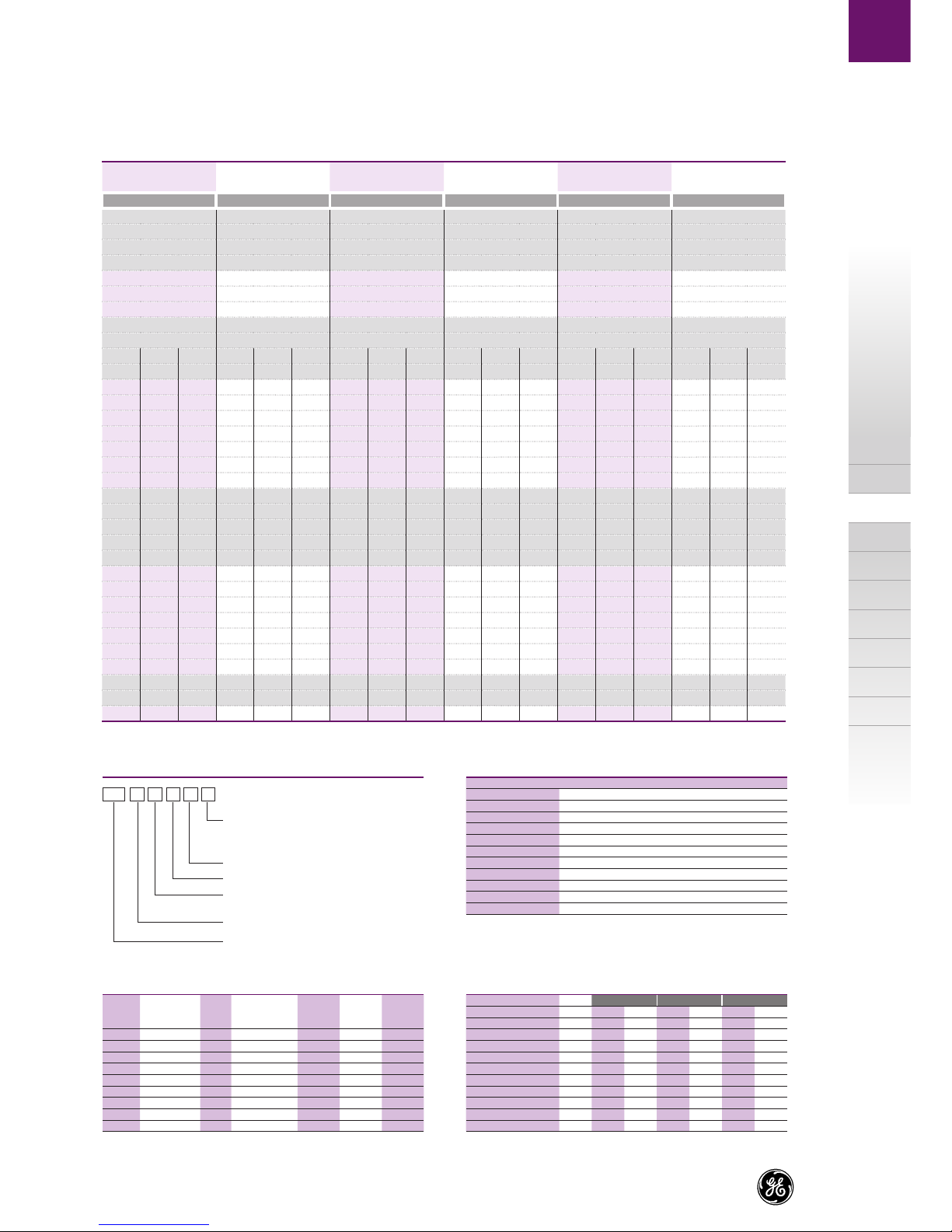
MS31F16
Ratings:
04-400A, 08-800A
10-1000A, 12-1250A
16-1600A, 20-2000A
25-2500A, 32-3200A
40-4000A
Installation: F-fixed, W-withdrawable
Type: 1-Frame1, 2-Frame2
* Letter 'L' & 'R' only for type selection, not shown on nameplate.
Breaking Capacity: S, N, H
M-PACT Plus
Pole: 3-3P
4-4P*
Recommended Minimum Copper Size
In accordance with IEC 60947-2
Rating (A) Copper / phase
400 2 x 50 x 5
800 2 x 50 x 5
1000 2 x 60 x 5
1250 2 x 100 x 5
1600 2 x 100 x 5
2000 3 x 100 x 5
2500 4 x 100 x 5
3200 4 x 100 x 10
4000 4 x 100 x 10 + 1 x 100 x 5
(1) Height is from mounting surface to highest part of the ACB.
(2) Depth is from the cubicle door to the back of terminals.
* 4P, Neutral on the left or right Please specify on selection form,the default
option is Neutral on right.
Catalogue Number Configuration
1200 1600 2000 2500 3200 4000
20000 20000 20000 20000 20000 20000
10000 10000 10000 10000 10000 10000
5000 5000 5000 5000 5000 5000
690 690 690 690 690 690
1000 1000 1000 1000 1000 1000
8000 8000 8000 8000 8000 8000
3 & 4 3 & 4 3 & 4 3 & 4 3 & 4 3 & 4
100% 100% 100% 100% 100% 100%
SNHSNHSNHSNHSNHSNH
1 1 2 1 1 2 1/2 1/2 2 1/2 1/2 2 2 2 2 2 2 2
50 65 80 50 65 80 50 65 80 50 65 80 50 65 80 50 65 80
50 65 80 50 65 80 50 65 80 50 65 80 50 65 80 50 65 80
50 65 80 50 65 80 50 65 80 50 65 80 50 65 80 50 65 80
50 50 65 50 50 65 50 50 65 50 50 65 50 50 65 50 50 65
40 40 60 40 40 60 40 40 60 40 40 60 40 40 60 40 40 60
50 65 80 50 65 80 50 65 80 50 65 80 50 65 80 50 65 80
50 65 80 50 65 80 50 65 80 50 65 80 50 65 80 50 65 80
50 65 80 50 65 80 50 65 80 50 65 80 50 65 80 50 65 80
50 50 65 50 50 65 50 50 65 50 50 65 50 50 65 50 50 65
40 40 60 40 40 60 40 40 60 40 40 60 40 40 60 40 40 60
50 65 80 50 65 80 50 65 80 50 65 80 50 65 80 50 65 80
40 50 50 40 50 50 40 50 50 40 50 50 40 50 50 40 50 50
143 143 176 143 143 176 143 143 176 143 143 176 143 143 176 143 143 176
143 143 176 143 143 176 143 143 176 143 143 176 143 143 176 143 143 176
143 105 143 143 105 143 143 105 143 143 105 143 143 105 143 143 105 143
84 84 105 84 84 105 84 84 105 84 84 105 84 84 105 84 84 105
175 105 60 287 196 98 224 224 163 224 224 163 418 418 418 571 571 571
351 211 128 574 392 209 490 490 347 490 490 347 888 888 888 1224 1224 1224

A.8
Technical overview
A
B
C
X
M-PACT Plus
State of the Art Electronic Trip Units
• A line offering a new range of electronic trip units designed to extend and/or upgrade the
functionality offered by the existing M-PACT Plus air circuit breaker.
• Two types are available. The simple and effective MPRO-27 and the MPRO-50 offering
extended functionality.
• Each has a LCD screen with ammeter and a menu driven setting interface, allowing a simple
and accurate setting of all parameters.
• This global line of electronic trip units uses the most recent technology to offer each user an
unique combination of selectivity speed and functionality.
Plug'n Play
Electronic trip units are normally supplied factory fitted.
However spares are available that can be simply plugged in
to breakers installed in the field.(1)
Each trip unit then needs to be adjusted to the required
settings. If the installation is not powered up the installed
battery pack or the seperately available test kit with Power
Pack can be used as alternate power source.
(1) When ordering a spare trip unit the serial number of the
installed breaker is needed for the factory settings
MPRO-27 & MPRO-50
The basic MPRO-27 type has been designed to replace
the existing MPRO-17 and MPRO-18 plus units offering an
extended functionality and a standard ammeter.
The MPRO-50 type replaces the existing MPRO-30 and
MPRO-40 designs covering an extended functionality with
protection devices as fuse links, overload protection and
reduced instantaneous (RELT). Each MPRO-50 comes with a
simple to connect 4 wire modbus communciation option.
Main Adjustment Options
LT-LTD protection
Each device has an overload setting range of 0.4 to a times
In and offer a choice of 22 time bands designed for use with
circuit breakers.
A second set of 22 time bands shaped to match the time
current curves of fuses is available on the MPRO-50 type.
ST-STD protection
A timed delayed short circuit protection is installed with a
current setting of 2 to 12 times the set LT current value. The
short circuit protection time can be set, at one of 17 bands
ranging from 90 milliseconds to 1 second.
Optionaly this device can be set to one of three I2t curves.
I-protection
A switchable and selective instantaneous protection with
a setting range of 2 to 15 times the breaker rating that is
programmed to wait one half cycle until the downstream
device has reacted.
Other protection features
A host of other protection devices is availble including Ground
Fault sum and Ground Fault source return (allowing UEF, SEF
& REF) and a reduced instantaneous device. The reduced
instanataneous device allows the user to conditionally
programme the breaker to trip faster and at lower short
circuit settings than it would on the standard instantaneuos
device.
This RELT device allows the user to reduce the short circuit
current level and its time span, thus reducing the amount of
electrical energy in the direct vicinity of the breaker.

A.9
M-PACT Plus
Electronic Trip Units
A
B
C
X
Trip Unit MPRO-27 MPRO-50
Setting Interface
LCD screen allowing access to 4 distinct menu's X X
Touch pad adjustments XX
Multilingual XX
Adjustable manual or automatic RESET option X X
Long Time or Overload Current Protection
13 current settings Ir 1, 0.95, 0.9. 0,85, 0.8, 0.75, 0.7, 0.65, 0.6, 0.55, 0.5, 0.45 & 0.4 x breaker rating In X X
22 thermal protection (C type) time bands available ranging from class 0.5 to 40 (bands at 7.2 x Ir) X X
22 I2t protection (F type {fuse} ) time bands available - X
Neutral protection 0-50%-63%-100% X X
Possibility to switch OFF -X
Cooling function and thermal memory X X
Short Time Short-Circuit Current Protection
Setting range from 1.5 to 12 x Ir (LT setting) X X
Steps of 0.5 (a total of 22 settings) X X
Possibility to switch OFF -X
17 time delay settings (STDB) ranging from 30 to 940 milliseconds delay setting,
resulting in 90 to 1000 milliseconds XX
Clearance times to IEC 40979-1 and IEC 60364
3 I2t protection time bands available
Instantaneous Short-Circuit Current
• Standard
Ii setting range from 2 to 15 x breaker rating In X X
Steps of 0.5 (a total of 28 settings) X X
Possibility to switch OFF XX
Selective execution XX
Fixed instantaneous or HSIOC protection X X
• Reduced
Ii setting range from 1.5 to 15 x Ie (primary setting) - X
Steps of 0.5 (a total of 29 settings) - X
Possibility to switch OFF -X
Remote and local ON and OFF with position indication signal - X
Ground or Earth Fault Protection
Setting range from 0.1 to 1 x In (breaker rating)(1) •(1) •(1)
Steps of 0.01 (a total of 92 settings) • •
Possibility to switch OFF ••
14 time delay settings (GFDB) ranging from 50 to 840 milliseconds delay setting,
resulting in 110 to 900 milliseconds ••
Clearance times to IEC 40979-1 and IEC 60364 • •
3 I2t protection time bands available • •
1 I4t protection time bands available • •
Residual principle (UEF application possible) • •
Source ground return principle - •
UEF, REF and SEF applications possible - •
Combinations of UEF, REF and SEF applications possible - •
Other Functions
Current measurement (L1, L2, L3, N) X X
Trip target (trip reason indication) X X
Trip info (magnitude / phase) XX
Trip counter XX
Event logger (trip events) XX
General inputs (4 available) -X
General relay outputs (4 available) - X
Relay based on current level (load shedding) - X
Good & bad health indicator -X
Watchdog -X
Communication 2 way -X
Modbus -X
(1)
24V DC auxiliary power supply • •
Test kit with power support function • •
(1) 24V auxiliary power supply is required.
Key
X = Present
• = Optional
- = Not possible

A.10
Technical overview
A
B
C
X
M-PACT Plus
MPRO Electronic Trip Unit
0,001
0,01
0,1
1
10
100
1000
10000
000001000010001
x Current in Amps (Strom in Ampere)
Tripping Time in Seconds (s)
Time Current Curve
Breaker In= 2500A
----------------------------------
LT - Protection device
Set at Ie= 2400A
Ir at 0,9 =2160A
Band C-10
ST - Protection device
Set at 6x Ir of 2160A
Ist=12960A
Band STDB 10
I - Protection device
Set at 12 x Ie of 2400A
Ii = 28800A
GF - Protection device
Set at 0,6 x Ie of 2500A
(Ig = 1500A)
Band GFDB 6
I²t ON & OFF
2h
7,2 x
Green & Light Blue Line = Full Clearing time
Red Line & Dark Blue Line = Non Tripping time
LT Band
ST Band
II Band
HSIOC Band
GF Band
Time Current Curves
The MPRO electronic trip unit has many sophisticated setting
features and an extremely broad setting range. On request
we can provide complete
Time Current Curves covering all installed protection devices.
The curves can be produced for any current setting within
the range of the installed protection devices, for one or for a
combination of two breakers.
Please contact your local GE Sales Office for more information.

A.11
M-PACT Plus
Time Current Curves
A
B
C
X
Time Current Curves (cold state) - LT Protection Device
MPRO 27 & 50 Electronic Trip Unit MPRO 27 & 50 Electronic Trip Unit
ST protection - OFF
I protection set to 15 x Ie(1)
ST protection - OFF
I protection set to 15 x Ie(1)
ST protection - OFF
I protection set to 15 x Ie(1)
ST protection - OFF
I protection set to 15 x Ie(1)
LT set at Breaker Rating In
Setting Range
Ie= 0.975, 0.9625, 0.95, 0.45 or 0.4 x In
Ir= 0.4 - 1 x Ie in steps of 0.25
Total Setting Range 0,2 - 1 x In
LT set at Breaker Rating In
Setting Range
Ie= 0.975, 0.9625, 0.95, 0.45 or 0.4 x In
Ir= 0.4 - 1 x Ie in steps of 0.25
Total Setting Range 0,2 - 1 x In
LT set at Breaker Rating In
Setting Range
Ie= 0.975, 0.9625, 0.95, 0.45 or 0.4 x In
Ir= 0.4 - 1 x Ie in steps of 0.25
Total Setting Range 0,2 - 1 x In
Time Current Curve
Band C-03
Band C-08
Band C-13
Band C-19
LT-Protection Device
-
-
-
-
-
Time Current Curve
Band C-06
Band C-11
Band C-16
Band C-22
LT-Protection Device
-
-
-
-
-
Time Current Curve
Band C-02
Band C-07
Band C-12
Band C-17
LT-Protection Device
-
-
-
-
-
Time Current Curve
Band C-04
Band C-09
Band C-14
Band C-20
LT-Protection Device
-
-
-
-
-
10000
2h
10000
2h
1000
100
10
Tripping Time In Seconds (s)
1
0,1
1,00 10,00 100,00
x Breaker Rating In
Tripping Time In Seconds (s)
0,1
1,00
x Breaker Rating In
7,2x
10,00 100,00
7,2x
Tripping Time In Seconds (s)
0,1
1,00
x Breaker Rating In
10,00 100,00
7,2x
Setting Range
Ie= 0.975, 0.9625, 0.95, 0.45 or 0.4 x In
Ir= 0.4 - 1 x Ie in steps of 0.25
Total Setting Range 0,2 - 1 x In
LT set at Breaker Rating In
1000
10
100
10000
2h
1000
10
100
1 1
Tripping Time In Seconds (s)
0,1
1,00
x Breaker Rating In
10,00 100,00
7,2x
10000
2h
1000
10
100
1

A.12
Technical overview
A
B
C
X
M-PACT Plus
MPRO 27 & 50 Electronic Trip Unit MPRO 27 & 50 Electronic Trip Unit
Time Current Curve
Band STDB 02
Band STDB 04
Band STDB 06
Band STDB 08
Band STDB 19
Band STDB 12
Band STDB 14
Band STDB 16
ST-Protection Device
I2t - OFF-
-
-
-
-
-
-
-
-
-
Time Current Curve
Band STDB 01
Band STDB 03
Band STDB 05
Band STDB 07
Band STDB 09
Band STDB 11
Band STDB 13
Band STDB 15
Band STDB 17
ST-Protection Device
I2t - OFF-
-
-
-
-
-
-
-
-
-
-
Green Line = Full Clearing Time
Red Line = Non Tripping Time
Green Line = Full Clearing Time
Red Line = Non Tripping Time
I protection set to 15 x Ie(1)
LT set at Breaker Rating In
Setting Range
Ie= 0.975, 0.9625, 0.95, 0.45 or 0.4 x In
Ir= 0.4 - 1 x Ie in steps of 0.25
Total Setting Range 0,2 - 1 x In
LT set at Breaker Rating In
Setting Range
Ie= 0.975, 0.9625, 0.95, 0.45 or 0.4 x In
Ir= 0.4 - 1 x Ie in steps of 0.25
Total Setting Range 0,2 - 1 x In
Time Current Curve
Band C-05
Band C-10
Band C-15
Band C-21
LT-Protection Device
- -
-
-
-
-
Time Current Curve
Band C-01
Band C-18
LT-Protection Device
-
-
ST protection - OFF
I protection set to 15 x Ie(1)
ST protection - OFF
I protection set to 15 x Ie(1)
ST set on breaker rating In
Setting Range
1,5 to 12 x Ir in steps of 0,5
ST set on breaker rating In
Setting Range
1,5 to 12 x Ir in steps of 0,5
16
17
15
17
15
13
11
9
7
5
3
1
13
11
9
7
5
3
1
14
12
10
16
14
12
10
8
6
4
2
8
6
4
2
x Breaker Rating In
x Breaker Rating In
x Breaker Rating In
Tripping Time In Seconds (s)
1,00 1,00
1,00 10,0010,00 100,00100,00
x Breaker Rating In
1,00
10,00 10,00
100,00 100,00
0,001 0,001
0,01 0,01
0,1
1
10
100
1000
2h
10000
2h
1000
100
10
1
0,1
10000
0,1 0,1
0,2 0,2
0,4 0,4
0,6 0,6
0,8 0,8
1 1
10 10
7,2x 7,2x
-
-
Time Current Curves (cold state) - LT & STDB Protection Device

A.13
M-PACT Plus
Time Current Curves
A
B
C
X
MPRO 27 & 50 Electronic Trip Unit MPRO 27 & 50 Electronic Trip Unit
10,00 100,00
10
0,8
1
0,6
0,4
0,2
0,1
00,1
0,01
1,00
Tripping Time In Seconds (s)
x Breaker rating In
10,00 100,00
10
0,8
1
0,6
0,4
0,2
0,1
00,1
0,01
1,00
Tripping Time In Seconds (s)
x Breaker rating In
10,00 100,00
10
0,8
1
0,6
0,4
0,2
0,1
00,1
0,01
1,00
Tripping Time In Seconds (s)
x Breaker rating In
10,00 100,00
10
0,8
0,6
0,4
0,2
0,1
00,1
0,01
1,00
Tripping Time In Seconds (s)
x Breaker rating In
17 16 16
14
12
10
8
6
4
2
16
14
12
10
8
6
4
2
14
12
10
8
6
4
2
16
14
12
10
8
6
4
2
15
17
15
13
13
11
11
9
9
7
7
5
5
3
3
1
17
15
17
15
13
13
11
11
9
7
9
7
5
5
3
3
1
1
1
Green Iine = Full Clearing time
Red Line = Non Tripping time
Green Iine = Full Clearing time
Red Line = Non Tripping time
I protection set to 15×Ie (1)
Green Iine = Full Clearing time
Red Line = Non Tripping time
I protection set to 15×Ie (1)
ST set at Breaker Rating In
1,5 to 12 × Ir in steps of 0,5
Setting Range
ST set at Breaker Rating In
1,5 to 12 × Ir in steps of 0,5
Setting Range
ST set at Breaker Rating In
1,5 to 12 × Ir in steps of 0,5
Setting Range
- Time Current Curve
- Band STDB 01
- Band STDB 03
- Band STDB 05
- Band STDB 07
- Band STDB 09
- Band STDB 11
- Band STDB 13
- Band STDB 15
- Band STDB 17
ST- Protection Device
I2t ON “Iow”
- Time Current Curve
- Band STDB 01
- Band STDB 03
- Band STDB 05
- Band STDB 07
- Band STDB 09
- Band STDB 11
- Band STDB 13
- Band STDB 15
- Band STDB 17
ST- Protection Device
I2t ON “med”
ST set at Breaker Rating In
1,5 to 12 × Ir in steps of 0,5
Setting Range
- Time Current Curve
- Band STDB 02
- Band STDB 04
- Band STDB 06
- Band STDB 08
- Band STDB 10
- Band STDB 12
- Band STDB 14
- Band STDB 16
ST- Protection Device
I2t ON “Iow”
- Time Current Curve
- Band STDB 02
- Band STDB 04
- Band STDB 06
- Band STDB 08
- Band STDB 10
- Band STDB 12
- Band STDB 14
- Band STDB 16
ST- Protection Device
I2t ON “med”
Green Iine = Full Clearing time
Red Line = Non Tripping time
I protection set to 15×Ie (1)
Time Current Curves (cold state) - ST Protection Device

A.14
Technical overview
A
B
C
X
M-PACT Plus
MPRO 27 & 50 Electronic Trip Unit MPRO 27 & 50 Electronic Trip Unit
10,00 100,00
10
0,8
1
0,6
0,4
0,2
0,1
0,01
0,01
1,00
Tripping Time In Seconds (s)
x Breaker rating In
10,00 100,00
10
0,8
0,6
0,4
0,2
0,1
0,01
0,01
1,00
Tripping Time In Seconds (s)
x Breaker rating In
ST set at Breaker Rating In
1,5 to 12 × Ir in steps of 0,5
Setting Range
I set on breaker rating In
2 to 15 × Ie in steps of 0,5
HSIOC device HSIOC device
HI Setting Range
I set on breaker rating In
2 to 15 × Ie in steps of 0,5
HI Setting Range
I set on breaker rating In
1,5 to 15 × Ie in steps of 0,5
RELT Setting Range
I set on breaker rating In
1,5 to 15 × Ie in steps of 0,5
RELT Setting Range
ST set at Breaker Rating In
1,5 to 12 × Ir in steps of 0,5
Setting Range
17
15
13
11
9
7
5 3 1
16 16
14 14
12 12
10
10
8
8
6
6
4 2 4 2
17
15
13
11
9
7
5
3 1
- Time Current Curve
- Band STDB 01
- Band STDB 03
- Band STDB 05
- Band STDB 07
- Band STDB 09
- Band STDB 11
- Band STDB 13
- Band STDB 15
- Band STDB 17
ST- Protection Device
I2t ON “max”
- Time Current Curve
I - Protection Device
RELT - Protection Device
- Time Current Curve
HI - Protection Device
RELT - Protection Device
- Time Current Curve
- Band STDB 02
- Band STDB 04
- Band STDB 06
- Band STDB 08
- Band STDB 10
- Band STDB 12
- Band STDB 14
- Band STDB 16
ST- Protection Device
I2t ON “max”
Green Iine = Full Clearing time
Red Line = Non Tripping time Green Iine = Full Clearing time
Red Line = Non Tripping time
I protection set to 15×Ie (1) I protection set to 15×Ie (1)
Green Iine = Full Clearing time
Red Line = Non Tripping time
Green Iine = Full Clearing time
Red Line = Non Tripping time
10,00 100,00
1
0,1
0,01
0,001
1,00
Tripping Time In Seconds (s)
x Breaker rating In
10,00 100,00
1
0,1
0,01
0,001
1,00
Tripping Time In Seconds (s)
x Breaker rating In
Time Current Curves (cold state) - ST, I and Hi Protection Device

A.15
M-PACT Plus
Time Current Curves
A
B
C
X
MPRO 27 & 50 Electronic Trip Unit MPRO 27 & 50 Electronic Trip Unit
- Time Current Curve
HSIOC - Protection Device
I - Present & ON
- Time Current Curve
HSIOC - Protection Device
I - PRESENT OFF
I Setting On
sei at 15kA ST Ser at 12,5kA
STDB 1
50 kA
100kA
85kA
65kA
50kA
65 kA
85 kA
100 kA
Green Iine = Full Clearing time
Red Line = Non Tripping time
Green Iine = Full Clearing time
Red Line = Non Tripping time
1
0,1
0,01
0,01
1000 10000 100000 10000,00
Tripping Time In Seconds (s)
Amps
1
0,1
0,01
0,01
1000 10000 100000 10000,00
Tripping Time In Seconds (s)
Amps
1,00 10,00
10
0,8
0,6
0,4
0,2
0,1
0,01
0,10
Tripping Time In Seconds (s)
x Breaker rating In
1,00 10,00
10
0,8
0,6
0,4
0,2
0,1
0,01
0,10
Tripping Time In Seconds (s)
x Breaker rating In
GF set on breaker rating In
0,1 to 1 × In in steps of 0,01
Setting Range
GF set on breaker rating In
0,1 to 1 × In in steps of 0,01
Setting Range
- Time Current Curve
- Band GFDB 01
- Band GFDB 03
- Band GFDB 05
- Band GFDB 07
- Band GFDB 09
- Band GFDB 11
- Band GFDB 13
GF- Protection Device
I2t -OFF-
- Time Current Curve
- Band GFDB 02
- Band GFDB 04
- Band GFDB 06
- Band GFDB 08
- Band GFDB 10
- Band GFDB 12
- Band GFDB 14
GF- Protection Device
I2t -OFF-
13
14 14
12 12
10 10
8
8
6
6
4
4
2
2
13
11
9
7
5
3
1
11
9
7
5
3
1
Green Iine = Full Clearing time
Red Line = Non Tripping time
Green Iine = Full Clearing time
Red Line = Non Tripping time
Time Current Curves (cold state) - HSIOC & GF Protection Device

A.16
Technical overview
A
B
C
X
M-PACT Plus
MPRO 27 & 50 Electronic Trip Unit MPRO 27 & 50 Electronic Trip Unit
1,00 10,00
10
1
0,8
0,6
0,4
0,2
0,1
0,01
0,10
Tripping Time In Seconds (s)
x Breaker rating In
1,00 10,00
10
1
0,8
0,6
0,4
0,2
0,1
0,01
0,10
Tripping Time In Seconds (s)
x Breaker rating In
1,00 10,00
10
1
0,8
0,6
0,4
0,2
0,1
0,01
0,10
Tripping Time In Seconds (s)
x Breaker rating In
1,00 10,00
10
0,8
0,6
0,4
0,2
0,1
0,01
0,10
Tripping Time In Seconds (s)
x Breaker rating In
GF set on breaker rating In
0,1 to 1 × In in steps of 0,01
Setting Range
GF set on breaker rating In
0,1 to 1 × In in steps of 0,01
Setting Range
GF set on breaker rating In
0,1 to 1 × In in steps of 0,01
Setting Range
- Time Current Curve
- Band GFDB 01
- Band GFDB 03
- Band GFDB 05
- Band GFDB 07
- Band GFDB 09
- Band GFDB 11
- Band GFDB 13
GF- Protection Device
I2t “low” -ON-
- Time Current Curve
- Band GFDB 02
- Band GFDB 04
- Band GFDB 06
- Band GFDB 08
- Band GFDB 10
- Band GFDB 12
- Band GFDB 14
GF- Protection Device
I2t “low” -ON-
13
13 13
11
9
7
5
3
1
11
9
7
5
3
1
14 14
12 12
10 10
8
6
4
2
8
6
4
2
14 14
12
10
8
6
4
2
12
10
8
6
4
2
11
9
7
5
3
1
13
11
9
7
5
3
1
Green Iine = Full Clearing time
Red Line = Non Tripping time
Green Iine = Full Clearing time
Red Line = Non Tripping time
Green Iine = Full Clearing time
Red Line = Non Tripping time
Green Iine = Full Clearing time
Red Line = Non Tripping time
- Time Current Curve
- Band GFDB 01
- Band GFDB 03
- Band GFDB 05
- Band GFDB 07
- Band GFDB 09
- Band GFDB 11
- Band GFDB 13
GF- Protection Device
I2t “med” -ON-
GF set on breaker rating Inv
0,1 to 1 × In in steps of 0,01
Setting Range
- Time Current Curve
- Band GFDB 02
- Band GFDB 04
- Band GFDB 06
- Band GFDB 08
- Band GFDB 10
- Band GFDB 12
- Band GFDB 14
GF- Protection Device
I2t “med” -ON-
Time Current Curves (cold state) - GF Protection Device

A.17
M-PACT Plus
Time Current Curves
A
B
C
X
MPRO 27 & 50 Electronic Trip Unit
1,00 10,00
MPRO 27 & 50 Electronic Trip Unit
10
1
0,8
0,6
0,4
0,2
0,1
0,01
0,10
Tripping Time In Seconds (s)
x Breaker rating In
1,00 10,00
1
0,8
0,6
0,4
0,2
0,1
0,01
0,10
Tripping Time In Seconds (s)
x Breaker rating In
GF set on breaker rating In
0,1 to 1 × In in steps of 0,01
Setting Range
GF set on breaker rating In
0,1 to 1 × In in steps of 0,01
Setting Range
- Time Current Curve
- Band GFDB 01
- Band GFDB 03
- Band GFDB 05
- Band GFDB 07
- Band GFDB 09
- Band GFDB 11
- Band GFDB 13
GF- Protection Device
I2t “max” -ON-
- Time Current Curve
- Band GFDB 02
- Band GFDB 04
- Band GFDB 06
- Band GFDB 08
- Band GFDB 10
- Band GFDB 12
- Band GFDB 14
GF- Protection Device
I2t “max” -ON-
13 13
11
9
7
5
3
1
11
9
7
5
3
1
14
12
10
8
6
4
4
6
8
10
12
14
2
2
Green Iine = Full Clearing time
Red Line = Non Tripping time
Green Iine = Full Clearing time
Red Line = Non Tripping time
Time Current Curves (cold state) - GF Protection Device

A.18
Technical overview
A
B
C
X
M-PACT Plus
Accessories
A wide range of optional accessories have been developed
that are compatible with all M-PACT Plus air circuit breakers,
regardless of nominal rating or frame size. Each one
incorporates 'easy-fit' design features for quick installation,
either in the factory or by the user on site.
Motorised spring charging unit
The unique motor/gearbox unit is specially designed to
operate with the full range of M-PACT Plus breakers.
It is easily fitted with just two bolts. In the event of circuit
breaker closure, this unit will automatically recharge the
spring in readiness for instant reclosure should the need
arise. High speed recharging ensures that the springs are
fully charged within approximately three seconds following a
release. As an optional feature, a "springs charged" contact is
available for the motor unit.
Circuit breaker closing coil
The closing coil is an easy-to-fit, clip-on unit, with simple
plug-in connectors. This permits either local or remote release
of the spring charged closing mechanism by electrical
operation.
An additional anti-pumping safety feature also ensures that
the electrical closing signal must be released before further
closure is attempted, and a cut-off is instigat-ed should a
closing signal be maintained.
Because each coil operates within a wide voltage range,
the number of individually rated coils required is drastically
reduced.
Shunt trip
Energisation, locally or remote, will instantaneously activate
the circuit breaker mechanism, ensuring rapid disconnection
of the main contacts.
In addition, a series connected auxiliary switch ensures
automatic isolation whenever the circuit breaker is open.
Shunt trip releases also have a wide operational voltage
range, and they include the same easy-fit, clip-on/plug-in
connectors as the closing coil above.
Undervoltage release
Instantaneously releases the circuit breaker trip mechanism
should the supply voltage dip below the pre-set value.
Simple to install, these devices have the same easy-fit
features as previously described.
Note: This is a 'no-volt/ no-close device. The circuit breaker
cannot be closed (manually or electrically) unless the
undervoltage release coil is energised.
Time delay undervoltage release Similar to the above, but
this electronic device prevents nuisance tripping of the circuit
breaker if circuit interruption is not desirable when supply
voltage drop is only transient. Fixed time delay 3 sec ±1sec.
Auxiliary trip combination
The M-PACT Plus circuit breaker can be equipped with the
following auxiliary trips or releases 1 x Shunt trip + 1 x Closing
coil + 1 x Undervoltage release or 1 time delay Undervoltage
release
Other manuals for M-Pact Plus
1
Table of contents
Other GE Circuit Breaker manuals

GE
GE Power Break II User manual

GE
GE A Series Pro-Stock THQB User manual

GE
GE AK-15 User manual

GE
GE CB Watch 3 User manual

GE
GE EntelliGuard GT-H User manual

GE
GE PowerVac User manual

GE
GE MicroVersaTrip Plus User manual

GE
GE WavePro 3200 A User manual

GE
GE MicroVersa Trip Plus User manual

GE
GE Spectra Series AMC6FGB User manual