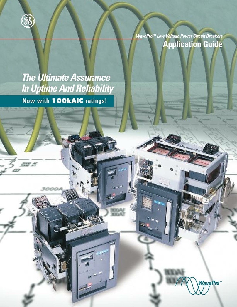
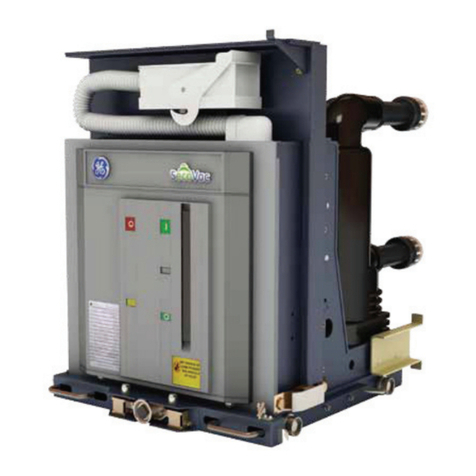
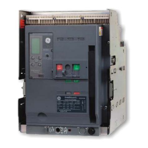
GE EntelliGuard G User guide

imagination at work
EntelliGuard®G
Circuit Breaker
Application Guide
GE Energy
Now with the following new ratings:
• Envelope 1, 100KAIC, 2000A and below
• Envelope 1, 65KAIC, 1200A and below
• Envelope 2, 100KAIC @ 600V rating
• UL489B DC Switch Ratings @ 600V and 1000V DC

DET-653C EntelliGuard®G Circuit Breaker Application Guide
24-May-12 Table of Contents
©2012 General Electric All Rights Reserved
SECTION 1 – GENERAL INFORMATION
Introduction.............................................................................................................................................................................................................. 1
Table 1.1. Device Standards and References ............................................................................................................................... 1
Table 1.2. Device Ratings ........................................................................................................................................................................ 1
Table 1.3. ANSI/UL1066 Ratings .......................................................................................................................................................... 2
Table 1.4. UL489 Ratings ......................................................................................................................................................................... 2
Table 1.5. Non-Automatic Circuit Breaker – ANSI Version Ratings ................................................................................... 2
Table 1.6. Non-Automatic Circuit Breaker/Molded Case Switch – UL Version Ratings.......................................... 2
Table 1.6b UL489B Ratings .................................................................................................................................................................... 3
SECTION 2 – FEATURES AND CHARACTERISTICS
Figure 2.1. EntelliGuard G Features and Characteristics ................................................................................................................. 4
STANDARD AND OPTIONAL FEATURES....................................................................................................................................................... 5
Short Time Rating (1/2 Sec)..................................................................................................................................................................... 5
Short Circuit/High Interruption Rating.............................................................................................................................................. 5
Thermal Performance ............................................................................................................................................................................... 5
Table 2.1. Sensors Available.......................................................................................................................................................... 5
Reverse Feed.................................................................................................................................................................................................. 5
Two-Step Stored Energy Mechanism................................................................................................................................................ 5
Field Installable Trip Units and Accessories................................................................................................................................... 5
Coils ............................................................................................................................................................................................................ 6
Breaker/Main Contact Status................................................................................................................................................................ 6
Motor Operator ............................................................................................................................................................................................. 6
Electrical Closing Button .......................................................................................................................................................................... 6
Ready to Close Indicator.......................................................................................................................................................................... 6
Mounting Straps/Accessories ............................................................................................................................................................... 6
Auxiliary Switches........................................................................................................................................................................................ 6
Interlocks.......................................................................................................................................................................................................... 6
Breaker Status Indicators........................................................................................................................................................................ 6
Rejection Feature......................................................................................................................................................................................... 7
Through-Door Racking.............................................................................................................................................................................. 7
Padlocking Devices..................................................................................................................................................................................... 7
Key Interlock................................................................................................................................................................................................... 7
Shutters ............................................................................................................................................................................................................ 7
Carriage Position Switch .......................................................................................................................................................................... 7
Lifting Beam.................................................................................................................................................................................................... 7
IP Covers........................................................................................................................................................................................................... 7
Mechanical Counter ................................................................................................................................................................................... 7
Cable Interlocks (OEM Applications Only)........................................................................................................................................ 8
Bell Alarm Contact....................................................................................................................................................................................... 8
SECTION 3 – ENTELLIGUARD TU TRIP UNIT SYSTEM
Introduction ............................................................................................................................................................................................................ 9
Reliability without Compromising Protection......................................................................................................................................... 9
Arc Flash and the EntelliGuard TU Trip Unit............................................................................................................................................ 9
Figure 3.1. Arcing Current......................................................................................................................................................................10
Selectivity with Molded case Circuit Breakers and Other Devices............................................................................................10
Figure 3.2. Selectivity Curve..................................................................................................................................................................10
Table 3.1. EntelliGuard Selectivity Above GE Current Limiting Circuit Breakers .......................................................10
Table 3.2. Maximum Instantaneous Pickup Multipliers for GE Circuit Breakers .......................................................11
Table 3.3. Selectivity with EntelliGuard TU Trip Units in ANSI and ICCB/ Power Break II Circuit Breakers..13
Above Downstream Feeders.........................................................................................................................................................................14
The Waveform Recognition Selective Instantaneous......................................................................................................................14
Table 3.4. Minimum Selective Clearing Times for an EntelliGuard G Circuit Breaker.............................................15

DET-653C EntelliGuard®G Circuit Breaker Application Guide
24-May-12 Table of Contents
©2012 General Electric All Rights Reserved
Above Other Power Circuit Breakers........................................................................................................................................................15
Terminology........................................................................................................................................................................................................... 15
Long Time Protection .................................................................................................................................................................................16
Thermal Long Time Overcurrent ................................................................................................................................................................ 16
Figure 3.3. Thermal Characteristic: Max. and Min. Long Time Delay Bands for a 1000A Long Time Pickup ...... 16
Table. 3.5. Thermal Characteristic: Nominal Clearing and Commit Times for X Multipliers of Nominal Pickup 17
Fuse-Shaped Steep Long Time Overcurrent........................................................................................................................................ 17
Figure 3.4. Fuse Characteristic: Max. and Min. Long Time Delay Bands for a 1000A Long Time Pickup............. 17
Table 3.6. Fuse Characteristic: Nominal Clearing and Commit Times for X Multipliers of Nominal Pickup........ 18
Thermal Memory.................................................................................................................................................................................................19
Short Time Protection....................................................................................................................................................................................... 19
Short Time Pickup .....................................................................................................................................................................................19
Figure 3.5. Short Time Pickup .................................................................................................................................................... 19
Figure 3.6. Short Time Transition .............................................................................................................................................19
Short Time Bands ......................................................................................................................................................................................20
Table 3.7. Short Time Delay Bands ......................................................................................................................................... 20
Figure 3.7 Short Time Delay ....................................................................................................................................................... 20
Short Time I2t Slopes................................................................................................................................................................................20
Figure 3.8. Short I2t (In or Out).................................................................................................................................................... 20
Ground Fault Protection..................................................................................................................................................................................20
Internal Residual Summation....................................................................................................................................................................... 20
External Zero Sequence Input...................................................................................................................................................................... 21
Ground Fault Pickup Settings.......................................................................................................................................................................21
Table 3.9. Ground Fault Time Delay Bands.................................................................................................................................. 21
Ground Fault Time Delay Bands................................................................................................................................................................. 21
Table 3.10. Minimum Ground Fault Pickup and Clear Time................................................................................................ 21
Ground Fault Protection Curves .................................................................................................................................................................21
Figure 3.9. Ground Fault Characteristics ...................................................................................................................................... 21
Instantaneous Protection............................................................................................................................................................................... 21
Adjustable Selective Instantaneous .........................................................................................................................................................22
Table 3.11. Max. Adjustable Instantaneous Pickup for CBs with Normal or Extended Range Option ......... 22
Table 3.12. Time Current Curves ....................................................................................................................................................... 22
High Set Instantaneous Overcurrent (HSOIC)...................................................................................................................................... 23
Making Current Release (MCR)..................................................................................................................................................................... 23
Table 3.13. HSIOC Locations................................................................................................................................................................ 23
Reduced Energy Let-Through (RELT) Instantaneous Trip .............................................................................................................. 23
Reduced Energy Let-Through Switch Wiring....................................................................................................................................... 24
Figure 3.10. Integrated Switch And LED, Spring Return from “Test” to ‘Off,” Latched in “On” .......................... 24
Zone Selective Interlocking (ZSI )................................................................................................................................................................ 24
Table 3.14. Instantaneous ZSI on EntelliGuard TU Trip Units in ANSI EntelliGuard G Circuit Breakers ........ 25
Figure 3.11. Zone Selective Interlocked CB, Upper CB Shown “Unrestrained” ......................................................... 25
Figure 3.12. Zone Selective Interlocked CB, Upper CB Shown “Restrained” .............................................................. 25
Rating Plugs...........................................................................................................................................................................................................26
Figure 3.13. EntelliGuard Trip Unit Rating Plug Catalog Number Guide ...................................................................... 26
Table 3.15. Trip Rating Plug Specifications.................................................................................................................................. 27
Table 3.16. Trip Rating Plug Codes................................................................................................................................................... 27
Table 3.17. EntelliGuard G Rating Plug Logic (UL 489,n UL 1066, IEC)........................................................................... 28
Universal Spare Trip Unit................................................................................................................................................................................28
Table 3.18. Universal Spare trip Unit Options (User-Selected)........................................................................................... 22
Relay Functions ................................................................................................................................................................................................... 29
Protective Relays.................................................................................................................................................................................................30
Voltage Unbalance Relay............................................................................................................................................................................... 30
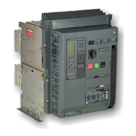
Table 3.19. Relay Functions Available in EntelliGuard G CBs with EntelliGuard TUs ............................................. 30
Table 3.20. Voltage Unbalance Settings ....................................................................................................................................... 30

DET-653C EntelliGuard®G Circuit Breaker Application Guide
24-May-12 Table of Contents
©2012 General Electric All Rights Reserved
Current Unbalance Relay................................................................................................................................................................................31
Table 3.21. Current Unbalance Settings ........................................................................................................................................31
Under Voltage Relay ..........................................................................................................................................................................................31
Under Voltage Relay Zero-Volt Trip Enable...........................................................................................................................................31
Table 3.22. Under Voltage Settings ..................................................................................................................................................31
Over Voltage Relay.............................................................................................................................................................................................31
Table 3.23. Over Voltage Settings .....................................................................................................................................................31
Power-Reversal Relay .......................................................................................................................................................................................31
Table 3.24. Power-Reversal Settings ...............................................................................................................................................31
Power-Direction Setup .....................................................................................................................................................................................31
Potential Transformer Primary Voltage...................................................................................................................................................31
Potential Transformer Connection.............................................................................................................................................................31
Power Demand Intervals.................................................................................................................................................................................31
Current Alarm........................................................................................................................................................................................................31
Trip Logic Inputs...................................................................................................................................................................................................31
Table 3.25 Input Assignments Possible..........................................................................................................................................32
Outputs for EntelliGuard G Circuit Breakers..........................................................................................................................................32
Table 3.26. Output Configuration ......................................................................................................................................................32
Waveform Capture.............................................................................................................................................................................................32
EntelliGuard Trip Unit Performance Characteristics Graphs........................................................................................................33
Table 3.27. EntelliGuard Trip Unit Summary................................................................................................................................33
Table 3.28. Metering Data Startup Levels for breaker with Entelliguard Trip Unit with 24 VDC ......................35
Table 3.29. Metering Data for breaker with Entelliguard Trip Unit without 24 VDC requires 20%
sensor current and then all metering will be available ...............................................................................35
Figure 3.14. Long Time Circuit Breaker Characteristics .......................................................................................................36
Figure 3.15. Short Time Pickup and Delay Bands .....................................................................................................................37
Figure 3.16. Ground Fault: Multiple of Sensor.............................................................................................................................38
Figure 3.17. Instantaneous, Override (HSIOC), Reduced Energy Let-Through Instantaneous (RELT) ............39
SECTION 4 – ACCESSORIES
Introduction ..........................................................................................................................................................................................................40
Figure 4.1. Accessory Mounting .........................................................................................................................................................40
Motorized Spring Charging Unit ..................................................................................................................................................................40
Table 4.1. Motor Operators ..................................................................................................................................................................40
Circuit Breaker Closing Coils – Standard and Commanded .........................................................................................................40
Table 4.2. Closing Coil Characteristics ............................................................................................................................................41
Command Operation Module.......................................................................................................................................................................41
Shunt Trip ................................................................................................................................................................................................................41
Table 4.3. Extended Range Shunt Trip for UL Ground Fault and ANSI DC Rating Applications........................41
Status Indication Switch (Coil Signaling Contact)...............................................................................................................................41
Table 4.4. Coil Signaling Contact Module......................................................................................................................................41
Under Voltage Release with Fixed Time Delay ....................................................................................................................................41
Table 4.5. UVR Operating Characteristics.....................................................................................................................................41
Time Delay Module for UVR (Externally Mounted)..............................................................................................................................42
Figure 4.2. Time Delay Module ..........................................................................................................................................................42
Table 4.6. TDM Characteristics ..........................................................................................................................................................42
Remote Operation Coil Combination........................................................................................................................................................42
Table 4.7. Remote Operation Coil Combination.........................................................................................................................42
Ready to Close Contact....................................................................................................................................................................................42
Table 4.8. Ready to Close Contacts (1NO).....................................................................................................................................42
Auxiliary Switches ...............................................................................................................................................................................................42
Table 4.9. Auxiliary Switches................................................................................................................................................................42
Table 4.10. Auxiliary Switch Ratings and Secondary Disconnect Points......................................................................42
Table 4.11. Power Rated (3NO/3NC) (Ref Drawing 10099230)...........................................................................................43
Table 4.12. Power Rated (8NO/8NC) (Ref Drawing 10099228)...........................................................................................43

DET-653C EntelliGuard®G Circuit Breaker Application Guide
24-May-12 Table of Contents
©2012 General Electric All Rights Reserved
Table 4.13. Power Rated (3NO/3NC) + Low Signal (Hi-Fi) (2NO/2NC) (Ref Drawing 10099232)........................ 43
Table 4.14. Power Rated (4NO/4NC) + Low Signal (Hi-Fi) (4NO/4NC) (Ref Drawing 10099234......................... 44
Circuit Breaker – Key Interlock Facility....................................................................................................................................................44
Table 4.15. Key Interlocks and Door Interlocks ......................................................................................................................... 44
Figure 4.3. Breaker-Mounted Key Interlock................................................................................................................................. 44
Figure 4.4. Cassette-Mounted Key Interlock............................................................................................................................... 44
Carriage Position Switch (TOC) ....................................................................................................................................................................45
Table 4.16. Carriage Position Switches.......................................................................................................................................... 45
Table 4.17. Carriage Position Switch Ratings (Common NO/NC Contact Configuration..................................... 45
Mechanical Interlocks (Cable/Rod) (OEM Applications Only) .............................................................................................. 45
Table 4.18. Mechanical Interlock (Cable/Rod) ............................................................................................................................ 45
Cables..............................................................................................................................................................................................................45
Table 4.19. Cables for Mechanical Interlocks............................................................................................................................. 45
Table 4.20. Interlock Configurations ............................................................................................................................................... 46
Bell Alarm with Lockout................................................................................................................................................................................... 47
Table 4.21. Bell Alarm Switches ......................................................................................................................................................... 47
Table 4.22. Bell Alarm Ratings (Common 1NO/NC Contact Configuration)................................................................ 47
Charging Spring Status Indicator...............................................................................................................................................................47
Table 4.23 Spring Charged Contact (1NO) ................................................................................................................................... 47
Secondary Disconnects (Factory-Installed/Field Installable) ...................................................................................................... 47
Table 4.24. Block Location....................................................................................................................................................................47
Table 4.25. Wiring Schematic for Block A..................................................................................................................................... 47
Table 4.26. Wiring Schematic for Block B..................................................................................................................................... 48
Table 4.27. Wiring Schematic for Block C..................................................................................................................................... 48
Table 4.28. Electronic Interlock .......................................................................................................................................................... 48
Table 4.29. Wiring Schematic Nomenclature Definitions .................................................................................................... 49
Ground Fault .........................................................................................................................................................................................................50
Table 4.30. Neutral Rogowski CTs .................................................................................................................................................... 50
Sealed Door Panel Escutcheon ................................................................................................................................................................... 50
Mechanical Operations Counter.................................................................................................................................................................50
Table 4.31. Miscellaneous Accessories.......................................................................................................................................... 50
Cassette/Substructure..................................................................................................................................................................................... 50
Position Indicators..............................................................................................................................................................................................50
Door Interlocks..................................................................................................................................................................................................... 51
Table 4.32. Door Interlocks................................................................................................................................................................... 50
Back Connected Terminations ....................................................................................................................................................................51
Table 4.33. Back Connected Terminations for Cassette....................................................................................................... 51
Table 4.34. Back Connected Terminations .................................................................................................................................. 53
Front Flat Terminations ...................................................................................................................................................................................56
Table 4.35. Optional Front Flat Terminations ............................................................................................................................. 56
Table 4.36. Cluster.....................................................................................................................................................................................57
Table 4.37. Cluster Pad ...........................................................................................................................................................................58
Terminations for DC Switches UL 489B .................................................................................................................................................. 59
Figure 4.35. Terminations for DC Switches UL 489B .............................................................................................................. 59
Remote Racker .............................................................................................................................................................................................. 59
Table 4.38. Remote Racker ................................................................................................................................................................59
Grounding/Earthing Device (IEC Only) ..................................................................................................................................................... 59
Table 4.39. Grounding/Earthing Devices (IEC Only.................................................................................................................. 59
Rejection Device.................................................................................................................................................................................................. 59

DET-653C EntelliGuard®G Circuit Breaker Application Guide
24-May-12 Table of Contents
©2012 General Electric All Rights Reserved
SECTION 5 – CATALOG NUMBERING GUIDE
EntelliGuard G ANSI/UL489 Circuit Breaker Catalog Number Guide .......................................................................................60
EntelliGuard G Cassette Catalog Number Guide................................................................................................................................68
EntelliGuard TU Trip Unit for EntelliGuard G Breaker .......................................................................................................................70
EntelliGuard TU Trip Unit Rating Plugs.....................................................................................................................................................72
SECTION 6 – APPLICATION DATA
Introduction ..........................................................................................................................................................................................................73
Key Features ..........................................................................................................................................................................................................73
UL1066 Low Voltage Power Circuit Breakers .............................................................................................................................73
UL498 Stored Energy Insulated Case Circuit Breakers..........................................................................................................73
IEC rated Circuit Breakers for IEC Equipment and Applications .......................................................................................73
All Types ..........................................................................................................................................................................................................73
Ratings and Sizes ................................................................................................................................................................................................73
Short Circuit Interrupting Ratings...............................................................................................................................................................74
Figure 6.1. Short Circuit Rating Adjustment Equation ............................................................................................................74
Table 6.1. First Half-Cycle Peak at Specific Fault X/R Ratios...............................................................................................74
Withstand Ratings, Selective Adjustable-, RELT- and Override-Instantaneous Protection .........................................74
Close and Latch Ratings and Making Current Release (MCR) Instantaneous Trip............................................................75
Table 6.2. EntelliGuard G Circuit Breaker Close and Latch Ratings, UL489 Listed ..................................................75
Table 6.3. EntelliGuard G Circuit Breaker Close and Latch Ratings, UL1066 Listed................................................75
Table 6.4. EntelliGuard G Non-Automatic Switch Close, Latch, and Withstand Ratings, UL489 Listed .......76
Operations ..............................................................................................................................................................................................................76
Table 6.5. Operational Ratings, UL489 Circuit Breakers........................................................................................................76
Table 6.6. Operational Ratings, UL1066/ANSI Circuit Breakers.........................................................................................76
Selecting a Circuit Breaker for an Application .....................................................................................................................................76
Cable or Bus Size – Factor A..........................................................................................................................................................................76
Ambient Temperature – Factor B ...............................................................................................................................................................77
Table 6.7. Ambient Temperature Rating – Factor B.................................................................................................................77
Operating Frequency – Factor C.................................................................................................................................................................77
Altitude – Factor D ..............................................................................................................................................................................................77
Table 6.8. Altitude Rating – Factor D................................................................................................................................................77
Load Class Rating – Factor E.........................................................................................................................................................................77
Table 6.9. Load class Rating – Factor E..........................................................................................................................................78
Safety – Factor F..................................................................................................................................................................................................78
Other Factors that Influence Circuit Breaker Sizing 100% vs. 80% Ratings........................................................................78
Table 6.10. Circuit Breaker and Trip Parameters ......................................................................................................................
78
SECTION 7 – PHYSICAL DATA
Dimensional Drawings .....................................................................................................................................................................................79
Figure 7.1. Sample Dimensional Drawing: ANSI UL 489, 3Pole, Drawout, 2000A, Type E, M .............................79
Dimensional Drawing Index ..........................................................................................................................................................................80
Table 7.1. Dimensional Drawing Index ...........................................................................................................................................80
Dimensions ..........................................................................................................................................................................................................81
Table 7.2. 3-Pole, UL/ANSI .....................................................................................................................................................................81
Table 7.3. 4-Pole, UL/ANSI .....................................................................................................................................................................81
SECTION 8 – STANDARDS AND REFERENCES
....................................................................................................................................................................82
Publications ..........................................................................................................................................................................................................85

DET-653C EntelliGuard®G Circuit Breaker Application Guide
24-May-12 Section 1. Introduction
©2012 General Electric All Rights Reserved
1
EntelliGuard®G Power Circuit Breaker
Section 1. Introduction
EntelliGuard G circuit breakers are the newest line of low voltage power circuit breakers (LVPCBs) evolved from the
exceptional designs and practices of GE legacy breakers. EntelliGuard G breakers offer a truly global product platform that
meets industry standards throughout the Americas, Europe and Asia (ANSI, UL, CSA, IEC, Lloyds Register of Shipping, etc.).
Breakers are available to OEMs in 3- and 4-pole designs from 400A to 6400A (IEC) with fault interruption ratings up to 150kA.
New, state-of-the-art EntelliGuard Trip Units enable the breakers with advanced technology that provides system
protection, local and remote monitoring, relaying and communications. EntelliGuard Trip Units may be supplied with either
Modbus or Profibus communications protocols. The breaker-trip unit system delivers superior circuit protection without
compromising selectivity or arc flash protection. The EntelliGuard system is yet another evolution of GE’s core competencies
in reliable electric power distribution, circuit protection and arc flash protection.
EntelliGuard G 3-pole breakers are the standard in GE AKD-20 Low Voltage Switchgear. The breakers are suitable for
280Vac, 480Vac and 600Vac applications, and they provide advanced circuit protection, limit arc fault energy and preserve
system coordination without sacrificing any of these critical functions (Table 1.1).
Table 1.1. Device Standards and References (See Section 8 for Details)
ANSI® Certified
UL® Listed
IEC® Rated
IEC® Extreme Atmospheric Conditions
Low-Voltage
Insulated Case
Circuit Breaker
IEC 68-2-1: Dry cold at -55°C
Power Circuit
Circuit Breaker
IEC 60947-1
IEC 68-2-2: Dry heat at 85°C
Breaker
UL 489
UL489B DC for
Photovoltaic
IEC 60947-2
IEC 68-2-30: Damp heat (temp. 55°C, rel. humidity 95%)
C37.13
NEMA AB1
IEC 60947-3 IEC 68-2-52 Level 2: salt mist
C37.16
CSA 22.2 NO 5.1
C37.17
C37.20
C37.50
UL 1066
NEMA SG3&5
EntelliGuard G devices are available in all standard, 100% rated, ANSI, UL and IEC ratings in both fixed and draw-out
designs. Standard devices are also offered in 4 pole designs. No compromise (e.g., derating) is necessary in the system
protection scheme as the EntelliGuard G Neutral poles are fully rated. Front and rear access connections are available, and
all configurations can be manually or electrically operated with multiple and redundant accessories (optional) (Table 1.2).
Table 1.2. Device Ratings
Standard
Sensors Available
Envelope 1
Envelope 2
Envelope 3
ANSI/UL
400A - 2000A
400A - 3200A
3200A - 5000A
UL 489
400A - 2000A
400A - 3200A
3200A - 6000A
IEC
400A - 2000A
400A - 4000A
3200A - 6400A
EntelliGuard G short circuit and interrupting ratings are given in Tables 1.3 through 1.6.

DET-653C EntelliGuard®G Circuit Breaker Application Guide
24-May-12 Section 1. Introduction
©2012 General Electric All Rights Reserved
2
Table 1.3. ANSI/UL1066 Ratings
Interrupting Rating Tier ANSI/UL1066 Devices, LVPCB
Envelope 1
Envelope 2
Envelope 3
Type
254V
508V
635V
1/2S
Withstand
400,
800,
1200
400, 800,
1600,
2000
3200
400-3200
3200
4000-
5000
S
65,000 65,000 50,000 50,000 X
N
65,000
65,000
65,000
65,000
X
X
H
85,000
85,000
65,000
65,000
X
P
100,000
100,000
65,000
65,000
X
E
85,000
85,000
85,000
85,000
X
M
100,000
100,000
100,000
85,000
X
X
B
100,000
100,000
100,000
100,000
X
X
L
150,000
150,000
100,000
100,000
X
X
Table 1.5. Non-Automatic Circuit Breaker – ANSI Version Ratings
Envelope
Type
Amps
Rated
Interrupting
Rated Endurance
Current
Minimum
Mechanical
Minimum
Electrical
Minimum
Electrical
Endurance
Endurance
at 480V
Endurance
at 600V
1
S
800
42
12,500 10,000 7,500
1
N
800
42
12,500
10,000
7,500
1
N
1600
42
12,500
10,000
7,500
1
N
2000
42
12,500
7,500
5,000
2
M
3200
65
5,000
5,000
5,000
3
B
4000
100
5,000
3,000
2,000
3
B
5000
100
5,000
2,000
1,500
•GE internal quality testing requirements exceeded 20,000 mechanical and electrical operations.
Table 1.4. UL489 Ratings
Interrupting Rating Tier UL489 Devices, ICCB
Envelope 1
Envelope 2
Envelope 3
Type
240V
480V
600V
1/2S
Withstand
400-
1200
400-
2000
2500-
3000
400-
3000
3000
4000
5000-
6000
S
65,000
65,000
50,000
42,000
X
N
65,000 65,000 65,000 42,000
X
X
H
85,000 85,000 65,000 50,000
X
X
P
100,000
100,000
65,000
50,000
X
M
100,000 100,000 100,000 65,000
X
X X
L
150,000 150,000 100,000 85,000
X X X

DET-653C EntelliGuard®Circuit Breaker Application Guide
24-May-12 Section 1. Introduction
©2012 General Electric All Rights Reserved
3
Table 1.6. Non-Automatic Circuit Breaker/Molded Case Switch – UL Version
Ratings
Envelope
Type
Amps
Short
Interrupting
Rated Endurance
Current (kA)
Minimum
Mechanical
Minimum
Electrical
Minimum
Electrical
Endurance
Endurance
at 480V
Endurance
at 600V
1
S
800
42
12,500
10,000
7,500
1
S
1200
42
12,500 10,000 7,500
1
N
800 42 12,500 10,000 7,500
1
N
1600
42
12,500
10,000
7,500
1
N
2000
42
12,500
7,500
5,000
2
M
3000 65 5,000 5,000 5,000
3
B
4000 100 5,000 3,000 2,000
3
B
5000
100
5,000
3,000
1,500
3
B
6000
100
5,000
1,500
1,000
•GE internal quality testing requirements exceeded 20,000 mechanical and electrical operations.
Table 1.6b UL489B Ratings "Suitable for use in Photovoltaic system in accordance with article 690 of the NEC"
Envelope
Type
Amps
Short
Interrupting
Rated Endurance
Current (kA)
Minimum
Mechanical
Endurance
Minimum
Electrical
Endurance
at 600V
DC
Minimum
Electrical
Endurance
at 1000V
DC
2
M
800 -
3000
30
12500
500
500
4 Configurations available for 600V DC and 1000V DC with or without isolating both DC legs.
See Page 59 for Bus Bar Configurations.. Note: Bus Bars must be ordered separately.
Time Constant (L/R) = 15msec, Rated calibration temperature 50 degree C
Altitudes and Closing Times
See Section 7, Tables 7.2 and 7.3.
Dimensions and Weights
See Section 7.

DET-653C EntelliGuard®G Circuit Breaker Application Guide
24-May-12 Section 2. Features and Characteristics
©2012 General Electric All Rights Reserved
4
EntelliGuard®G Power Circuit Breaker
Section 2. Features and Characteristics
Figure 2.1. EntelliGuard G Features and Characteristics

DET-653C EntelliGuard®G Circuit Breaker Application Guide
24-May-12 Section 2. Features and Characteristics
©2012 General Electric All Rights Reserved
5
STANDARD AND OPTIONAL FEATURES
Short Time Rating (1/2 Sec)
42KA, 50KA, 65KA (Env 1); 85KA (Env 2), 100KA (Env 3)
Short Circuit/High Interruption Rating
65K - 150KA @ 508V and below, 65K - 100KA @ 635V
Thermal Performance
ANSI C37 and UL 489 designs are 100% rated up to 40ºC when
applied in recommended enclosure sizes. IEC 60947 versions are
100% rated in free air up to 50ºC. IP31 enclosure/switchboard
rating is based on size, recommended up to 50ºC ambient with
rear vertical bus connection (Table 2.1).
Reverse Feed
EntelliGuard G devices can be fed from top or bottom terminals.
Two-Step Stored Energy Mechanism
EntelliGuard G operates via stored energy mechanisms that can
be manually charged (MO) or electrically charged (EO) by the
Spring Charging Motor. Closing time is less than five cycles.
Closing and opening can be initiated remotely or via the front
cover push buttons. An Open-Close-Open cycle is possible
without recharging. (Charge after close). The breaker operating
mechanism is a trip-free mechanism and is furnished with an
integrated anti-pumping system.
Field Installable Trip Units and Accessories
EntelliGuard G devices have provisions for four accessory
operating coils. The four positions can be filled by the following
four devices: one Close Coil (CC) or one Command Close Coil (CCC),
one Shunt Trip Coil (ST), one Under Voltage Release (UVR), and the
fourth position can either be a 2nd ST Coil or a UVR. The Shunt
Trip and the UVR can also be replaced with a 120V Network
Interlock Device. The closing coil is a “one-shot” electronic closed
circuit. Shunt trip (ST) coils are continuous rated. (Note: No Red
Indicating Light on Shunt Trip) Under voltage relays (UVR) are
available with a fixed time delay (3 Cycles at down to 50% system
voltage; 1.2 Cycles below 50% system voltage). The time delay
module (TDM) is available as a shipped loose accessory for
remote installation (in equipment). Optional Coil Signaling contact
modules for the CC, CCC, ST, UVR, and NI's provide coil status
(energize/de-energize) via the secondary disconnects or trip unit
through Modbus or Profibus Comm.
Table 2.1 Enclosure Requirements
Minimum
Specified Cubicle
Space (inches)
Minimum Specified Cubicle Ventilation - No of
Vent Slots (a)
Frame Size
No. of Poles
W
H
D
Top Wall
Bottom Wall
Rear Wall
1200A (Env 1)
3P
20
16.4
16.5
12
16
-
2000A (Env 1)
3P
20
16.4
16.5
12
16
-
2000A (Env 1)
4P
22
16.4
16.5
12
16
-
3000A/3200A (Env 2)
3P
22
21
16.5
16
16
8
3000A/3200A (Env 2)
4P
25
21
16.5
20
16
8
6000A (Env 3)
3P
32
30
16.5
24
20
20
6000A (Env 3)
4P
41
30
16.5
30
24
20

DET-653C EntelliGuard®G Circuit Breaker Application Guide
24-May-12 Section 2. Features and Characteristics
©2012 General Electric All Rights Reserved
6
Coils
EntelliGuard G devices have provisions for four accessory
operating coils. The four positions can be filled by the following
four devices: one Close Coil (CC or CCC), one Shunt Trip Coil, one
UVR (Under Voltage Release), and the fourth position can either
be a Shunt Trip Coil or a UVR. The closing coil is a “one-shot”
electronic closed circuit. Shunt trip (ST) coils are continuous rated.
Under voltage relays (UVR) are available with a fixed time delay
(50ms at down to 50% system voltage; 20ms below 50% system
voltage). The time delay module (TDM) is available as a shipped-
loose accessory for remote installation (in equipment). Optional
status contact modules for the ST, CC and UVRs provide coil
status (energize/de-energize) via the secondary disconnects and
trip unit.
Breaker/Main Contact Status
OPEN/CLOSED, ON/OFF indication is provided on the front cover.
Motor Operator
Heavy duty, motor/gearbox unit; easily accessible with a full
range of voltages.
Electrical Closing Button
Located on the front cover between the Open and Close button;
used to electronically close the breaker when a Command Close
Coil is selected.
Ready to Close Indicator
Provides visible indication/readiness for close operation.
Mounting Straps/Accessories
Kits are available to mount and connect fixed/stationary breakers
in either a rear connected (Vertical) or a front flat connected.
Auxiliary Switches
Four available designs:
•Power rated (3NO+3NC) (Standard)
• Power rated (3NO+3NC) + low signal (Hi-Fi) (2NO+2NC)
• Power rated (8NO+8NC)
• Power rated (4NO+4NC) + low signal (Hi-Fi) (4NO+4NC)
Interlocks
Standard interlocks include:
• Drawout Breaker: prevents the breaker from being closed
unless it is in the TEST or CONNECT positions
• Drawout Breaker/Main Contacts: prevents withdrawal/removal
of the breaker unless the main contacts are OPEN. Access to the
drawout mechanism racking screw is blocked when the breaker
is CLOSED.
• Spring Discharge Interlock: Automatically discharges the
closing springs when the breaker is moved from the DISCONNECT
to the WITHDRAWN position. This prevents withdrawing a breaker
from the cubicle with the closing springs charged.

DET-653C EntelliGuard®G Circuit Breaker Application Guide
24-May-12 Section 2. Features and Characteristics
©2012 General Electric All Rights Reserved
7
Breaker Status Indicators
Standard Indicators include:
• The breaker status indicator shows the condition of the main
contacts (OPEN, CLOSED).
• The status of the closing springs is indicated as CHARGED or
DISCHARGED.
• The draw-out position indicator displays whether the breaker is
in the CONNECT, TEST or DISCONNECT position.
• The breaker also includes a switch that provides main contact
status indication to the POWER LEADER™ Power Management
System.
• The optional Reduced Energy Let-Through (RELT) is provided
with an ON/OFF contact closure to positively indicate whether the
RELT setting is enabled or not.
Rejection Feature
A factory-installed rejection feature prevents mismatching
breakers and cassettes/substructures. This prevents (a) inserting
a breaker with a lower interrupting rating into a higher rated
cassette/substructure and (b) inserting a higher current rated
breaker into a lower rated cassette/substructure.
Through-Door Racking
The breaker racking mechanism is accessible through the front of
the cassette and permits safely disconnecting/withdrawing the
circuit breaker without opening the door and exposing personnel
to live parts during the process.
Padlocking Devices
The padlocking device is standard on breakers and allows up to
three padlocks with 1/4" to 3/8" diameter shanks to secure the
breaker in the OPEN/TRIP FREE position. A padlock provision on
the front panel of the cassette/substructure permits locking
access to the racking screw. Racking access can be locked with
the breaker in the CONNECT, TEST, DISCONNECT position with up
to three padlocks.
Key Interlock
Up to four optional key interlocks are available (Kirk, Ronis,
Profalux, Castell). Switchgear applications utilize a Kirk key
interlock mounted in the cassette. A maximum of two key
interlocks may fit in the cassette.
Shutters
Optional lockable shutters are available (factory installed).
Carriage Position Switch
This optional cassette/substructure device permits local or
remote indication of the circuit breaker status (CONNECTED, TEST,
DISCONNECTED), 2NO/2NC single pole, double throw contacts are
available for each position.
Lifting Beam
Optional Lifting Beams/bars with separate slings are available for
all breaker sizes. A Universal Lifting Beam is also available
capable of lifting a 3 Pole Envelope 1
IP Covers
Optional IP54 covers (protects against harmful amounts of dust
and splashing water) are available for all breaker sizes.
Mechanical Counter
Provides local record of the cumulative number of complete
breaker closing operations.

DET-653C EntelliGuard®G Circuit Breaker Application Guide
24-May-12 Section 2. Features and Characteristics
©2012 General Electric All Rights Reserved
8
Cable Interlocks (OEM Applications Only)
Available for fixed and draw-out breakers, these units enable
direct interlocking of EntelliGuard G circuit breakers.
Bell Alarm Contact
Available with or without a mechanical lockout feature, the bell
alarm operates whenever the breaker trips due to a protective
function (electrical fault).

DET-653C EntelliGuard®G Circuit Breaker Application Guide
24-May-12 Section 3. EntelliGuard TU Trip Unit System
©2012 General Electric All Rights Reserved
9
EntelliGuard G Power Circuit Breaker
Section 3. EntelliGuard TU Trip Unit System
Introduction
The EntelliGuard TU Trip Unit offers optimum circuit
protection and optimum system reliability simultaneously
with little or no compromise to either of these critical
functions. Reliability and arc flash protection, in one
package, at the same time, all the time.
EntelliGuard TU series trip units are available as the
standard controller for new production EntelliGuard G
ANSI/UL 1066, UL 489 and IEC circuit breakers. EntelliGuard
TU designs are also available as direct, functional
replacements for GE's PowerBreak, PowerBreak II, WavePro,
AKR, and AK circuit breakers. EntelliGuard TU trip units are
also available in kit form for many popular non-GE and older
GE low voltage power circuit breakers (Refer to DEH-4567).
The EntelliGuard® TU technology is also available in GE's
molded case Spectra Breaker line 400A-1200A. The Spectra
MET (microEntelliGuard) includes the innovative RELT and
Zone Selective Interlocking- Instantaneous feature. New, on-
board features and communications capabilities enable
equipment enhancements, improved operational
performance and life extension programs. Performance will
vary based on associated circuit breaker and equipment
conditions. All EntelliGuard TU Trip Units are Conformal
Coated for increased reliability in humid/damp
environments.
This section describes the functions as implemented in the
EntelliGuard G UL 489 and ANSI/UL 1066 circuit breakers.
References or comparisons to other GE circuit breakers are
for informational purposes only.
Reliability without Compromising Protection
Reliable protection of circuits and equipment has always
been the circuit breaker’s primary mission. Providing
appropriate protection of the conductors, while preserving
selective coordination, has been the primary focus of most
system designers. However, what was acceptable in the
past is no longer the standard today.
Modern economic reality, coupled with strict regulatory
requirements, demand optimal system performance with
increased sensitivity to the inherent power system hazards
that face operating and maintenance personnel. Safety
agencies, local authorities and owner-operators demand
better personnel protection and state-of-the-art capabilities
to minimize hazards while simultaneously preserving critical
loads and system capabilities.
These requirements often seem to be, and sometimes are, in
conflict, pitting the speed and sensitivity required to improve
arc flash protection against the delays and deliberate
decision making required to maximize power system
reliability. The EntelliGuard TU, along with the EntelliGuard
family of circuit breakers, offers flexible solutions for
demanding circuit protection and circuit preservation
environments. The EntelliGuard TU is designed to provide the
utmost in system protection and reliability simultaneously,
with little or no compromise.
Arc Flash and the EntelliGuard TU Trip Unit
Reducing arc flash hazard is a primary concern in many
power system designs. The best way to ensure the lowest
possible hazard for a particular distribution system is to
consider the hazard as the system is designed and make
careful selection of the system’s topology, circuit sizes,
equipment sizes and protective devices to minimize hazard
for the operating and maintenance personnel that will need
to use the system for years to come.
The EntelliGuard TU, especially in conjunction with the
EntelliGuard G circuit breaker, provides significant flexibility
towards solving arc flash hazard problems without
excessive sacrifice of system reliability, in terms of
selectivity.
The next three to four pages are an overview of the
EntelliGuard TU's unique features enabling Arc Flash
mitigation and selectivity at the same time. When the
downstream breaker/fuse is current limiting, the Waveform
Recognition Selective Instantaneous is used to achieve lower
Instantaneous pickup settings while maintaining selectivity.
This is very effective for 250A and below devices. For Feeder
devices above 250A, the Instantaneous Zone Selective
Interlocking (I-ZSI) feature is used to achieve selectivity and
arc flash mitigation at the same time. The I-ZSI feature is
available on Spectra MET and EntelliGuard® TU in the
following breakers: EntelliGuard G, Power Break II, WavePro,
AK/AKR, and Conversion Kits. By combining the Waveform
Recognition Selective Instantaneous and I-ZSI, a system with
a 100KAIC bolted fault current can achieve a 8 cal/cm2 or
less incident energy level.
One way to lower potential incident energy is to ensure that
circuit breakers are able to interrupt using their
Instantaneous trips for all expected arcing faults. Figure 3.1
shows the expected arcing currents for 480V systems for
various arc gaps representative of switchgear (32mm),
switchboards (25mm), MCCs (25mm) and panelboards
(13mm). These values were determined using IEEE standard
1548, Guide for Performing Arc-Flash Hazard Calculations,
2002.

DET-653C EntelliGuard®G Circuit Breaker Application Guide
24-May-12 Section 3. EntelliGuard®TU Trip Unit System
©2012 General Electric All Rights Reserved
10
Figure 3.1. Arcing Current
Figure 3.1 demonstrates the wide range of possible arcing
currents predicted by the IEEE standard’s calculations. The
actual arcing currents may be lower or higher when
consideration is given to the potential error in short circuit
calculations, fault current data provided by the utility
company, and variance in the actual arcing gap or
enclosure’s geometry where the arc occurs. Of particular
concern should be the lower end of the possible range of
current that may fall below the Instantaneous pickup of a
circuit breaker or the current limiting threshold of a fuse.
Dangerous incident energy may quickly increase when
interruption time increases from a few cycles to a few
seconds, even for low arcing current.
Selectivity with Molded Case Circuit Breakers and Other
Devices
The EntelliGuard TU trip unit’s Waveform Recognition
Selective Instantaneous provides a unique selectivity
capability. When used in conjunction with current limiting
devices downstream, the trip unit may be set low, and still
maintain significant levels of selectivity. Table 3.1 lists the
minimum instantaneous setting above specific GE circuit
breakers and the levels of selectivity achieved. Testing and
documentation of the selectivity capability of the
EntelliGuard Trip unit will be expanded as more test data
becomes available. Always consult GE Selectivity reference
publication DET-537 for the latest information or contact
your GE sales representative for up to date information.
Selectivity above current limiting fuses may also be
expected. The required minimum setting may be estimated
by examining the peak let-through curve for the fuse. Find
the peak let-through current value that is 1.41 times the
prospective RMS current. The trip unit should be set such
that the instantaneous pickup is above that peak value. The
circuit breaker and fuse may then be selective up to the
values identified in Table 3.1. The fuse and circuit breaker
combinations have not been tested so performance cannot
be guaranteed at this time; however, selectivity is expected
for arcing and bolted faults up to the values indicated in the
above selectivity table.
Protection between circuit breakers using the EntelliGuard
TU trip unit may be further improved using zone selective
interlocking. The trip unit’s unique instantaneous zone
selective interlocking which can increase selectivity for UL
489 EntelliGuard G mains while allowing to trip
instantaneously for faults within their zone of protection
allows significant selectivity and arc flash protection at the
same time.
Selectivity for an EntelliGuard TU ground fault function and a
circuit breaker below may be enhanced by the trip unit’s
selective ground fault function and zone selective
interlocking. Figure 3.2 demonstrates an 800A circuit
breaker under a 1200A ground fault set to be fully selective.
See also Tables 3.2 and 3.3.
Figure 3.2. Selectivity Curve

DET-653C EntelliGuard®G Circuit Breaker Application Guide
24-May-12 Section 3. EntelliGuard TU Trip Unit System
©2012 General Electric All Rights Reserved
11
Table 3.1. EntelliGuard Selectivity Above GE Current Limiting Circuit Breakers
Selectivity between any line side (main)Circuit Breaker with a GE EntelliGuard TU trip unit and a load side (branch) GE current
limiting circuit breaker, and certain lighting panel type circuit breakers is determined based on the setting of the line side
EntelliGuard TU Trip. When the line side EntelliGuard TU Trip unit is set at the value defined in the table or higher the pair is
selective over the instantaneous range of the upstream CB up to the limit defined in the table below. The required settings are
independent of the line side circuit breaker type and only depend on the load side current limiting circuit breaker. The table
below identifies the values for GE's currently produced UL listed current limiting molded case circuit breakers.
Extent of selectivity will depend on line side circuit breaker type. The table below describes how that selectivity is limited by
circuit breaker type.
The table below applies at 208 through 480 Volts except where specifically limited to 240V and lower.
Notes:
1. EntelliGuard TU must employ a 400A rating plug or larger
2. EntelliGuard TU must employ an 800A rating plug or larger
3. Any instantaneous overlap seen in time current curves when line side CB is set per table does not indicate a lack of
selectivity and may be ignored.
Load side (branch)
devices
Line side (Main) device with EntelliGuard TU trip unit
Frame
Designation
Maximu
m Trip
(frame
or
sensor)
EntelliGuard TU
instantaneous
setting must be
> than (3)
PowerBreak
II, UL 489 CB
Wavepro,
AKR or AK,
or other
ANSI CB
without a
mechanical
override
EntelliGuard
G, UL489 CB EntelliGuard
G, ANSI CB
Record Plus G
600A
20,350A
Up to short
circuit rating;
65kA, 100kA
or 150kA at
480V, and
200kA at
240V
Up to short
circuit rating;
65kA, 100kA
or 150kA at
480V.
Up to
withstand
rating; 42kA,
50kA, 65kA,
85kA or
100kA at
480V
Up to
withstand
rating; 65kA,
85kA or
100kA at
480V
Record Plus G
400A
Record Plus G
250A
Record Plus E
250A
9,900A (1)
Record Plus E
150A
Record Plus E
100A
Record Plus E
60A
Record Plus E
30A
Record Plus
B/C
100A 7,190A
Spectra G
600A
29,980A
Spectra G
400A
Spectra G
250A
Spectra F
250A
11,200A (2)
Spectra E
150A
9,600A (2)
TECL
3 & 7A
800A (1)
TECL
15A
850A (1)
TECL
30A
1,800A (1)
TECL
50A
3,800A (1)
TECL
100A
7,300A (1)
TECL
150A
11,000A (1)
TEY/TEYF
15-100A
9,900A (1)
14,000A
14,000A
14,000A
14,000A
THQL (240V)
15-60A
9,900A (1)
10,000A
10,000A
10,000A
10,000A
THHQL
(240V)
15-60A 9,900A (1) 22,000A 22,000A 22,000A 22,000A

DET-653C EntelliGuard®G Circuit Breaker Application Guide
24-May-12 Section 3. EntelliGuard®TU Trip Unit System
©2012 General Electric All Rights Reserved
12
•Instantaneous selectivity between a circuit breaker with an EntelliGuard TU trip Unit and any non-current limiting circuit breaker may be evaluated via
traditional time current curve analysis or simply multiplying the upstream instantaneous trip setting by .9 which accounts for the tolerance of the line
side circuit breaker around the nominal setting. If The EntelliGuard TU's Instantaneous zone selective interlocking capability between similarly equipped
circuit breakers is employed then selectivity up to the upstream circuit breaker's full withstand or short circuit rating is possible.
The table below identifies maximum instantaneous pickup multipliers possible for various types and sizes of GE circuit
breakers. Lower part of table identifies the maximum instantaneous pickup in amperes for various circuit breaker, sensor and
rating plug combinations.
Table 3.2. Maximum Instantaneous Pickup Multipliers for GE Circuit Breakers
Line side device with Entelliguard TU Trip Unit
PowerBreak II,
UL 489 CB
WavePro or AKR,
ANSI CB
EntelliGuard G,
ANSI/UL Std I
EntelliGuard
G, ANSI Ext I
Max Instantaneous in X
Frame
determines
maximum
instantaneous
pickup (X) for PB2
and WP CB.
Plug/Icw ratio
determines
maximum
possible for
EntelliGuard G
CB. EntelliGuard
values shown are
more maximum
withstand tiers.
800A frame
15
15
15
30
1600A frame
15
15
15
30
2000A frame 15 15 15 30
2500A frame 13 N/A 15 30
3000A frame
13
N/A
15
30
3200A frame
N/A
13
15
30
4000A frame 10 10 15 23
5000A frame N/A 7 15 19
6000A frame
N/A
N/A
15
16
Amperes
Amperes
800A frame, 800A plug 12,000 12,000 12,000 24,000
1600A frame, 1600A plug 24,000 24,000 24,000 48,000
2000A frame, 2000A plug
30,000
30,000
30,000
60,000
2500A frame, 2500A plug
32,500
N/A
37,500
75,000
3000A frame, 3000A plug 39,000 N/A 45,000 90,000
3200A frame, 3200A plug N/A 41,600 48,000 96,000
4000A frame, 4000A plug
40,000
52,000
60,000
92,000
5000A frame, 5000A plug
N/A
65,000
75,000
95,000
6000A frame, 6000A plug N/A N/A 90,000 96,000
Maximum instantaneous is a multiple of rating plug, the above values may be lower if a smaller rating plug than
maximum for frame is used. In PB2 & WavePro CB maximum instantaneous multiplier is limited by frame rating. In
Entelliguard G the maximum Instantaneous X may be limited by circuit breaker withstand or short time rating (also
known as Icw).

DET-653C EntelliGuard®G Circuit Breaker Application Guide
24-May-12 Section 3. EntelliGuard TU Trip Unit System
©2012 General Electric All Rights Reserved
13
Table 3.3. Selectivity with EntelliGuard TU Trip Units in ANSI and ICCB/ Power Break II Circuit Breakers
Downstream device with
EntelliGuard TU Trip Unit
Power Break II,
UL 489 CB
WavePro or AKR,
ANSI CB
EntelliGuard G,
ANSI/UL Std I
EntelliGuard
G, ANSI Ext I
Max Instantaneous in X
Frame determines
maximum
instantaneous
pickup (X) for PB II
and WP CB.
Plug/Icw ratio
determines
maximum possible
for EntelliGuard
GCB. EntelliGuard
values shown are
more maximum
withstand tiers.
800A frame
15
15
15
30
1600A frame
15
15
15
30
2000A frame
15
15
15
30
3000A frame
13
N/A
15
30
3200A frame
N/A
13
15
30
4000A frame
10
10
15
23
5000A frame
N/A
7
15
19
6000A frame
(UL 489 only)
N/A
N/A
15
N/A
Amperes per above multipliers
800A frame,
800A plug
12,000
12,000
12,000
24,000
1600A frame,
1600A plug
24,000
24,000
24,000
48,000
2000A frame,
2000A plug
30,000
30,000
30,000
60,000
3000A frame,
3000A plug
39,000
N/A 45,000
90,000
3200A frame,
3200A plug
N/A
41,600
48,000
96,000
4000A frame,
4000A plug
40,000
40,000
60,000
92,000
5000A frame,
5000A plug
N/A
35,000
75,000
95,000
6000A frame,
6000A plug
N/A N/A 90,000
N/A
•Maximum instantaneous is a multiple of rating plug. The above values may be lower if a smaller rating plug than maximum for frame is used. In PB II &
WavePro circuit breakers, the maximum instantaneous multiplier is limited by frame rating. In EntelliGuard G, the maximum Instantaneous X may be
limited by circuit breaker withstand or short time rating (also known as Icw). The current numbers above multiplied by 0.9 provide maximum selectivity
above non-current limiting if instantaneous is adjusted to maximum and no zone selective interlocking is used.
Note: For complete listing of all selectivity functionalities see publication DET-537D

DET-653C EntelliGuard®G Circuit Breaker Application Guide
24-May-12 Section 3. EntelliGuard®TU Trip Unit System
©2012 General Electric All Rights Reserved
14
Above Downstream Feeders
The EntelliGuard TU trip unit has Short Time bands under
100msec designed to optimally fit above the Instantaneous
clearing times of various GE circuit breakers. Table 3.4 lists
the suggested Short Time band that may be used above
specific GE circuit breakers for the fastest coordination and
consequently fastest EntelliGuard G circuit breaker
interruption.
Also listed is the Hazard Risk Category for various available
fault currents calculated at the listed Short Time band
clearing times and Instantaneous clearing times provided by
the EntelliGuard TU trip unit’s Waveform Recognition
Selective Instantaneous and its Reduced Energy Let-Through
(RELT) Instantaneous trip. The Hazard Risk Category (HRC)
levels shown are calculated for a solidly grounded, 480V
system, 32mm arc gap, 18 in. working distance and arc in
box. Using the optimized Short Time band allows the system
to stay at HRC2 most of the time and always less than HRC4.
However, use of the RELT Instantaneous trip allows the
system to protect at HRC1 or 2 for available fault currents as
high as 90kA.
The Waveform Recognition Selective Instantaneous
The Instantaneous algorithm in the EntelliGuard TU trip unit
will allow a large switchboard or switchgear circuit breaker
to be set low yet maintain selectivity. For example, when set
to protect the conductors to a motor control center, an 800A
feeder circuit breaker’s Instantaneous may be set as low as
8kA nominal. This should provide complete selectivity above
the typical 150A and smaller circuit breakers or fuses found
in a motor control center.
Allowing for 10% pickup tolerance in the Instantaneous
pickup of the feeder circuit breaker would indicate that the
feeder would pickup Instantaneously for arcing fault
currents approximately 9kA or higher. From Figure 3.1 it can
be seen that fault currents of 20-25kA and higher would
seem to reliably produce arcing current above 9kA in a
variety of configurations. From Table 3.4 it can be seen that
an EntelliGuard G circuit breaker clearing instantaneously
can maintain HRC1 in a system with up to 42kA available
and HRC2 in systems with up to 100kA available – excellent
arc flash protection and selectivity simultaneously!
Note: These incident energy calculations do not take into
account motor contribution or other factors that may affect
expected levels of incident energy or hazard. For a thorough
understanding of the incident energy available or HRC in a
power distribution system, an Arc Flash Study should be
conducted by engineering personnel qualified to provide
such analysis.
Other manuals for EntelliGuard G
5
Table of contents
Other GE Circuit Breaker manuals

GE
GE GL 310 F1/4031 P/VR User manual

GE
GE EntelliGuard AKR30S-800A User manual

GE
GE ReliaGear Pro-Stock Spectra RMS User manual

GE
GE GCCC024DR User manual

GE
GE Power Break II User manual

GE
GE EntelliGuard G User guide

GE
GE AK-1-15 Series Owner's manual

GE
GE PVDB-28kV User manual

GE
GE Power Break II User manual

GE
GE AKR User manual
Popular Circuit Breaker manuals by other brands

Allen-Bradley
Allen-Bradley Guardmaster 442G-MABR-URM-C03 manual

Eaton
Eaton Crouse-Hinds F892 instruction manual

Siemens-Allis
Siemens-Allis LA-3200A instructions

Allis-Chalmers
Allis-Chalmers LA-25 Instructions for Installation, Care and Operation

Siemens
Siemens SION operating instructions

ABB
ABB S 280 UC Series Technical data