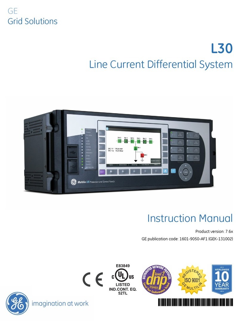
GE Multilin F650 User manual

*GEK-113000AF*
F650 Digital Bay Controller
GE
Grid Solutions
User Guide
Firmware version: 7.5x
EnerVista F650 Setup version: 7.5x
GE publication code: GEK-113000-AF
LISTED

© 2017 GE Multilin Inc. All rights reserved.
GE Multilin F650 Feeder Protection System instruction manual for revision AF.
F650 Feeder Protection System, EnerVista, and EnerVista 650 family
Setup are registered trademarks of GE Multilin Inc.
The contents of this manual are the property of GE Multilin Inc.
This documentation is furnished on license and may not be reproduced in
whole or in part without the permission of GE Multilin. The content of
this manual is for informational use only and is subject to change without notice.
Part number: GEK-113000-AF (June 2017)

GEK-113000-AF F650 DIGITAL BAY CONTROLLER 1-1
F650 Digital Bay Controller
Table of Contents
GE
Grid Solutions
1 GETTING STARTED 1.1 Important procedures ..................................................................................... 1-1
1.1.1 Cautions and warnings ....................................................................................................... 1-1
1.1.1.1 General cautions and warnings.................................................................................................1-2
1.1.1.2 Communication board withdrawal/insertion......................................................................1-3
1.1.1.3 Magnetic module terminals.........................................................................................................1-4
1.1.2 Inspection checklist............................................................................................................... 1-5
1.1.3 Safety instructions................................................................................................................. 1-7
1.1.3.1 General safety instructions..........................................................................................................1-8
1.1.3.2 Warning symbols..............................................................................................................................1-9
1.2 Overview .......................................................................................................... 1-10
1.2.1 Introduction to the 650 family of relays....................................................................1-10
1.2.2 Hardware architecture......................................................................................................1-10
1.2.2.1 F650 basic design.......................................................................................................................... 1-10
1.2.2.2 F650 signal type............................................................................................................................. 1-11
1.2.3 Communications architecture .......................................................................................1-11
1.3 EnerVista 650 Setup software...................................................................... 1-14
1.3.1 System requirements.........................................................................................................1-14
1.3.2 Installation...............................................................................................................................1-14
1.3.3 Connecting EnerVista 650 Setup to the F650.........................................................1-18
1.3.3.1 Configuring an Ethernet connection .................................................................................... 1-18
1.3.3.2 Configuring the RS232 connection....................................................................................... 1-18
1.4 650 hardware .................................................................................................. 1-19
1.4.1 Mounting & wiring................................................................................................................1-19
1.4.2 650 communications..........................................................................................................1-19
1.4.3 Faceplate display.................................................................................................................1-20
1.4.4 Maintenance...........................................................................................................................1-21
1.4.4.1 General maintenance.................................................................................................................. 1-21
1.4.4.2 In-service maintenance.............................................................................................................. 1-21
1.4.4.3 Out-of-service maintenance .................................................................................................... 1-21
1.4.4.4 Unscheduled maintenance....................................................................................................... 1-21
1.4.5 Storage......................................................................................................................................1-21
1.4.6 Repairs.......................................................................................................................................1-22
1.4.7 Disposal.....................................................................................................................................1-22
2PRODUCT
DESCRIPTION
2.1 F650 Overview................................................................................................... 2-1
2.2 ANSI device numbers and functions............................................................. 2-3

1-2 F650 DIGITAL BAY CONTROLLER GEK-113000-AF
CHAPTER 1:
2.3 Other device functions .................................................................................... 2-4
2.4 Order codes ....................................................................................................... 2-5
2.4.1 CIO Modules ..............................................................................................................................2-7
2.5 Technical specifications.................................................................................. 2-8
2.5.1 Protection ...................................................................................................................................2-8
2.5.2 Control.......................................................................................................................................2-16
2.5.3 Monitoring...............................................................................................................................2-19
2.5.4 User-programmable ..........................................................................................................2-21
2.5.5 Metering ...................................................................................................................................2-22
2.5.6 Inputs.........................................................................................................................................2-22
2.5.7 Real time clock......................................................................................................................2-24
2.5.8 Outputs.....................................................................................................................................2-24
2.5.9 Control power supply ........................................................................................................2-24
2.5.10 Communications..................................................................................................................2-25
2.5.11 Optical.......................................................................................................................................2-27
2.5.12 Environmental .......................................................................................................................2-28
2.5.13 Packaging and weight.......................................................................................................2-28
2.5.14 Type tests ................................................................................................................................2-28
2.5.15 Approvals.................................................................................................................................2-29
2.6 External connections .....................................................................................2-30
3INTERFACES,
SETTINGS & ACTUAL
VALUES
3.1 EnerVista 650 Setup software ........................................................................ 3-1
3.1.1 Introduction...............................................................................................................................3-1
3.1.1.1 Using settings files ........................................................................................................................... 3-2
3.1.1.2 Viewing actual values..................................................................................................................... 3-2
3.1.1.3 Viewing triggered events .............................................................................................................. 3-2
3.1.1.4 Firmware upgrades......................................................................................................................... 3-2
3.1.1.5 One line diagrams............................................................................................................................ 3-2
3.1.2 Main screen ...............................................................................................................................3-3
3.1.3 Connect to the relay..............................................................................................................3-4
3.1.3.1 Computer Settings: .......................................................................................................................... 3-5
3.1.3.2 Communication Control: ............................................................................................................... 3-5
3.1.3.3 Communication Optimization:.................................................................................................... 3-5
3.1.4 File management menu ......................................................................................................3-6
3.1.4.1 Offline mode........................................................................................................................................3-6
3.1.4.2 Online mode........................................................................................................................................ 3-8
3.1.5 EnerVista 650 Setup menu..............................................................................................3-10
3.1.6 File menu .................................................................................................................................3-11
3.1.6.1 New, Open, Save, Save as, and Close ..................................................................................3-12
3.1.6.2 Configuration file converter.......................................................................................................3-13
3.1.6.3 Properties ...........................................................................................................................................3-15
3.1.6.4 Print options......................................................................................................................................3-15
3.1.6.5 Compare to settings file ..............................................................................................................3-16
3.1.6.6 PLC checksum calculation .........................................................................................................3-16
3.1.6.7 Setting checksum calculation ..................................................................................................3-17
3.1.7 Setpoint menu.......................................................................................................................3-17
3.1.7.1 Product setup menu......................................................................................................................3-18
3.1.7.2 Communication settings menu ...............................................................................................3-18
3.1.7.3 System setup menu ......................................................................................................................3-19
3.1.7.4 Breaker menu...................................................................................................................................3-19
3.1.7.5 Protection elements menu.........................................................................................................3-19
3.1.7.6 Control elements menu ...............................................................................................................3-22
3.1.7.7 Inputs/Outputs menu ...................................................................................................................3-23
3.1.7.8 Quick settings menu .....................................................................................................................3-24
3.1.7.9 Relay configuration menu..........................................................................................................3-24
3.1.7.10 Logic Configuration menu..........................................................................................................3-26
3.1.7.11 IEC 103 Configuration menu....................................................................................................3-27

CHAPTER 1:
GEK-113000-AF F650 DIGITAL BAY CONTROLLER 1-3
3.1.7.12 Clock menu ....................................................................................................................................... 3-27
3.1.8 Actual values menu.............................................................................................................3-28
3.1.8.1 Front panel........................................................................................................................................ 3-28
3.1.8.2 Status................................................................................................................................................... 3-28
3.1.8.3 Metering ............................................................................................................................................. 3-30
3.1.8.4 Inputs/Outputs menu................................................................................................................... 3-31
3.1.8.5 Records menu ................................................................................................................................. 3-31
3.1.9 Operations menu..................................................................................................................3-32
3.1.10 Communications menu.....................................................................................................3-32
3.1.11 Security menu........................................................................................................................3-34
3.1.12 View menu...............................................................................................................................3-35
3.1.13 Help menu ...............................................................................................................................3-35
3.2 Human-machine interface (HMI) ................................................................ 3-36
3.2.1 Display.......................................................................................................................................3-37
3.2.2 LED indicators ........................................................................................................................3-38
3.2.3 Pushbuttons............................................................................................................................3-38
3.2.3.1 Keypad and shuttle key.............................................................................................................. 3-38
3.2.3.2 Command push button............................................................................................................... 3-40
3.2.4 Front port and cover sealing system..........................................................................3-40
3.2.5 Screen contrast.....................................................................................................................3-41
3.2.6 Text menus..............................................................................................................................3-41
3.2.6.1 Navigation......................................................................................................................................... 3-41
3.2.6.2 Text menu hierarchy.................................................................................................................... 3-42
3.2.6.3 Actual Values ................................................................................................................................... 3-42
3.2.6.4 Snapshot events............................................................................................................................. 3-44
3.2.6.5 Fault report ....................................................................................................................................... 3-45
3.2.6.6 View settings menu....................................................................................................................... 3-47
3.2.6.7 Change Settings ............................................................................................................................. 3-51
3.2.6.8 Date & time....................................................................................................................................... 3-52
3.2.6.9 Commands........................................................................................................................................ 3-53
3.2.6.10 Passwords ......................................................................................................................................... 3-54
3.2.6.11 Select main screen........................................................................................................................ 3-56
3.2.6.12 Select language.............................................................................................................................. 3-56
3.2.7 Graphic display .....................................................................................................................3-57
3.2.7.1 One-line diagram........................................................................................................................... 3-57
3.2.7.2 Metering screen.............................................................................................................................. 3-58
3.2.7.3 All events screen ............................................................................................................................ 3-59
3.2.7.4 New events screen........................................................................................................................ 3-61
3.2.7.5 Alarms panel .................................................................................................................................... 3-62
3.2.7.6 Input/output monitoring screen ............................................................................................. 3-63
3.3 Web server......................................................................................................3-66
3.3.1 Home..........................................................................................................................................3-66
3.3.2 Snapshot events ...................................................................................................................3-67
3.3.3 Control events........................................................................................................................3-68
3.3.4 Alarms........................................................................................................................................3-69
3.3.5 Oscillography .........................................................................................................................3-70
3.3.6 Fault report..............................................................................................................................3-71
3.3.7 Data logger .............................................................................................................................3-72
4 SECURITY 4.1 Adding users...................................................................................................... 4-1
4.1.1 User rights ................................................................................................................................. 4-1
4.2 Changing passwords ....................................................................................... 4-2
4.3 Enabling security.............................................................................................. 4-3
4.4 Logging into EnerVista 650 Setup ................................................................. 4-4

1-4 F650 DIGITAL BAY CONTROLLER GEK-113000-AF
CHAPTER 1:
5 BOOTCODE AND
FIRMWARE
UPGRADE
5.1 Firmware upgrade versions below 7.00. ...................................................... 5-1
5.1.1 Communication parameters.............................................................................................5-3
5.1.2 Bootware version upgrade.................................................................................................5-4
5.1.2.1 Bootware upgrade........................................................................................................................... 5-4
5.1.3 Firmware version upgrade..............................................................................................5-12
5.1.3.1 Introduction.......................................................................................................................................5-12
5.1.3.2 Firmware upgrade .........................................................................................................................5-12
5.1.4 Summary of main steps ...................................................................................................5-20
5.1.4.1 Boot code upgrade (*) ..................................................................................................................5-20
5.1.4.2 Firmware upgrade(*).....................................................................................................................5-21
5.2 Firmware upgrade version 7.00 or above..................................................5-22
5.2.1 Communication parameters..........................................................................................5-22
5.2.2 Firmware version upgrade..............................................................................................5-23
5.2.2.1 Introduction.......................................................................................................................................5-23
5.2.2.2 Firmware upgrade .........................................................................................................................5-23
5.2.2.3 Order code upgrade process....................................................................................................5-26
5.2.3 Summary of main firmware upgrade steps............................................................5-28
6 COMMISSIONING 6.1 Visual inspection............................................................................................... 6-1
6.2 Out of service setting....................................................................................... 6-2
6.3 General considerations, power supply network ......................................... 6-3
6.4 Isolation tests.................................................................................................... 6-4
6.5 Indicators ........................................................................................................... 6-5
6.6 Power supply testing ....................................................................................... 6-5
6.7 Communications............................................................................................... 6-5
6.8 Verification of measurement ......................................................................... 6-6
6.8.1 Voltages.......................................................................................................................................6-6
6.8.2 Phase currents .........................................................................................................................6-6
6.8.3 Active, reactive power, and COSJ metering...............................................................6-7
6.8.4 Frequency ..................................................................................................................................6-8
6.9 Inputs and outputs........................................................................................... 6-9
6.9.1 Digital inputs .............................................................................................................................6-9
6.9.2 Contact outputs....................................................................................................................6-10
6.9.3 Circuit continuity supervision inputs ..........................................................................6-10
6.9.4 Latching circuits...................................................................................................................6-10
6.10 Connections for testing protection elements ..........................................6-11
6.11 Instantaneous overcurrent (50PH, 50PL, 50N, 50G, 50SG) .....................6-12
6.12 Time overcurrent (51PH, 51PL, 51N, 51G, 46) ...........................................6-13
6.13 Directional elements (67P, 67N, 67G, 67SG)..............................................6-14
6.13.1 67P element............................................................................................................................6-14
6.13.2 67N element...........................................................................................................................6-14
6.13.3 67G element...........................................................................................................................6-15
6.13.4 67SG element ........................................................................................................................6-15
6.14 Undervoltage elements (27P, 27X)..............................................................6-17
6.14.1 27P element............................................................................................................................6-17
6.14.2 27X element ...........................................................................................................................6-17
6.15 Overvoltage elements (59P, 59X, 59NH, 59NL, 47)...................................6-18
6.15.1 59P element............................................................................................................................6-18
6.15.2 59X element ...........................................................................................................................6-18
6.15.3 59NH and 59NL elements................................................................................................6-19
6.15.4 47 element - Neg Seq OV.................................................................................................6-19
6.16 Frequency elements (81O/81U)...................................................................6-21
6.17 Recloser (79)....................................................................................................6-22
6.17.1 Reclosing cycle .....................................................................................................................6-22

CHAPTER 1:
GEK-113000-AF F650 DIGITAL BAY CONTROLLER 1-5
6.17.2 Recloser status ......................................................................................................................6-23
6.17.3 External reclose initiation.................................................................................................6-23
6.18 Thermal image element (49)........................................................................6-24
7FREQUENTLYASKED
QUESTIONS
7.1 Communications .............................................................................................. 7-1
7.2 Protection .......................................................................................................... 7-3
7.3 Control & HMI .................................................................................................... 7-4
7.4 Relay configuration.......................................................................................... 7-5
8 F650
TROUBLESHOOTING
GUIDE
8.1 Symptoms and recommended actions......................................................... 8-1
A LOGIC OPERANDS A.1 Operands - F650 - model FX - GX ..................................................................A-1
BREDUNDANCY
PROTOCOL
B.1 PRP and HSR Ethernet protocols ..................................................................B-1
B.1.1 PRP ...............................................................................................................................................B-4
B.1.2 HSR ...............................................................................................................................................B-5
B.2 RSTP (IEEE 802.1D-2004) and daisy chain ...................................................B-6
B.2.1 RSTP description ....................................................................................................................B-6
B.2.2 RSTP concepts ........................................................................................................................B-6
B.2.3 Use in meshed networks ...................................................................................................B-7
B.2.4 Daisy chain ..............................................................................................................................B-7
B.3 Link loss alert (LLA) ..........................................................................................B-8
B.3.1 LLA ................................................................................................................................................B-8
B.3.2 LLA priority ...............................................................................................................................B-8
B.3.3 LLA timeout ..............................................................................................................................B-8
C FACTORY DEFAULT
LOGIC
D FACTORY DEFAULT
CONFIGURATION
D.1 Factory default settings ................................................................................D-1
D.2 Factory default configuration .................................................................... D-28
E MISCELLANEOUS E.1 GE Multilin warranty ....................................................................................... E-1

1-6 F650 DIGITAL BAY CONTROLLER GEK-113000-AF
CHAPTER 1:

GEK-113000-AF F650 DIGITAL BAY CONTROLLER 1-1
F650 Digital Bay Controller
Chapter 1: Getting Started
GE
Grid Solutions
GETTING STARTED
1.1 Important procedures
Use this chapter for initial setup of your new F650 Digital Bay Controller.
1.1.1 Cautions and warnings
To help ensure years of trouble free operation, please read through the following chapter for information to help guide you
through the initial installation procedures of your new relay.
Before attempting to install or use the relay, it is imperative that all warnings and cautions in this manual are reviewed to
help prevent personal injury, equipment damage, and/or downtime.
The following safety and equipment symbols are used in this document.
DANGER
Indicates a hazardous situation which, if not avoided, will result in death or serious injury.
WARNING
Indicates a hazardous situation which, if not avoided, could result in death or serious injury.
CAUTION
Indicates a hazardous situation which, if not avoided, could result in minor or moderate injury.
NOTICE
Indicates practices not related to personal injury.

1-2 F650 DIGITAL BAY CONTROLLER GEK-113000-AF
1.1 IMPORTANT PROCEDURES CHAPTER 1: GETTING STARTED
1.1.1.1 General cautions and warnings
The following general safety precautions and warnings apply.
Follow the requirements of this manual, including adequate wiring size and type, terminal torque settings, voltage,
current magnitudes applied, and adequate isolation/clearance in external wiring from high to low voltage circuits.
Use the device only for its intended purpose and application.
Ensure that all ground paths are uncompromised for safety purposes during device operation and service.
Ensure that the control power applied to the device, the AC current, and voltage input match the ratings specified on
the relay nameplate. Do not apply current or voltage in excess of the specified limits.
Only qualified personnel are to operate the device. Such personnel must be thoroughly familiar with all safety
cautions and warnings in this manual and with applicable country, regional, utility, and plant safety regulations.
Hazardous voltages can exist in the power supply and at the device connection to current transformers, voltage
transformers, control, and test circuit terminals. Make sure all sources of such voltages are isolated prior to
attempting work on the device.
Hazardous voltages can exist when opening the secondary circuits of live current transformers. Make sure that
current transformer secondary circuits are shorted out before making or removing any connection to the current
transformer (CT) input terminals of the device.
For tests with secondary test equipment, ensure that no other sources of voltages or currents are connected to such
equipment and that trip and close commands to the circuit breakers or other switching apparatus are isolated,
unless this is required by the test procedure and is specified by appropriate utility/plant procedure.
When the device is used to control primary equipment, such as circuit breakers, isolators, and other switching
apparatus, all control circuits from the device to the primary equipment must be isolated while personnel are working
on or around this primary equipment to prevent any inadvertent command from this device.
Uses an external disconnect to isolate the mains voltage supply.
Figure 1-1: Front view of F650 unit
WARNING
Ensure that all connections to the product are correct so as to avoid accidental risk of shock
and/or fire, for example such as can arise from high voltage connected to low voltage terminals.
WARNING
LED transmitters are classified as IEC 60825-1 Accessible Emission Limit (AEL) Class 1M. Class 1M
devices are considered safe to the unaided eye. Do not view directly with optical instruments.
NOTICE
This product is rated to Class A emissions levels and is to be used in Utility, Substation Industrial
environments. Not to be used near electronic devices rated for Class B levels.

CHAPTER 1: GETTING STARTED 1.1 IMPORTANT PROCEDURES
GEK-113000-AF F650 DIGITAL BAY CONTROLLER 1-3
1.1.1.2 Communication board withdrawal/insertion
The modular design of the relay allows for the withdrawal and insertion of the communication module.
Figure 1-1: Module withdrawal/insertion shows the location of communication modules on the rear part of the relay.
Qualified personnel must carry out the insertion or extraction of the communication boards only after disconnecting the
relay auxiliary voltage and ensuring that all the rear terminals are potential free.
Communication boards are installed on the rear of the unit, with upper port reserved for the asynchronous
communications board and CAN bus, and the lower port for the ETHERNET board. (The Ethernet module can be withdrawn
or inserted only in models with Rear Ethernet Communication Board 2: "B", "C", "D" or "E". For the remaining options,
Ethernet communications are included in the main CPU).
Figure 1-1: Module withdrawal/insertion
WARNING
MODULE WITHDRAWAL AND INSERTION SHALL ONLY BE PERFORMED BY DULY QUALIFIED
SERVICE PERSONNEL. FOR PERSONAL SECURITY PURPOSES, BEFORE ACCOMPLISHING ANY
WITHDRAWAL OR INSERTION OPERATION, THE RELAY MUST BE POWERED OFF AND ALL THE REAR
TERMINALS MUST BE POTENTIAL FREE. THE RELAY MUST BE GROUNDED USING THE REAR
GROUNDING SCREW.
Before performing any of these actions, control power must be removed from the relay and all the rear terminals must
be potential free. A grounded antistatic wristband must be used when manipulating the module in order to avoid
electrostatic discharges that may cause damage to the electronic components.
WITHDRAWAL: Loosen the small screws that keep the faceplate in place and extract the module.
INSERTION: Insert the module and press it firmly in the case, until it is completely fixed. After this, bolt the faceplate
screws and replace the control power. Check that the relay is fully operative.
GE Multilin will not be responsible for any damage to the relay, connected equipment or personnel whenever these
safety rules are not followed.

1-4 F650 DIGITAL BAY CONTROLLER GEK-113000-AF
1.1 IMPORTANT PROCEDURES CHAPTER 1: GETTING STARTED
1.1.1.3 Magnetic module terminals
The transformer module for the VTs and CTs is already connected to a female connector screwed to the case. The current
inputs incorporate shorting bars, so that the module can be extracted without the need to short-circuit the currents
externally. It is very important, for safety reasons, not to change or switch the terminals for CTs and VTs.
Figure 1-1: Rear view of F650 unit
GE Multilin will not be responsible for any damage of the relay, connected equipment or personnel whenever
these safety rules are not followed.

CHAPTER 1: GETTING STARTED 1.1 IMPORTANT PROCEDURES
GEK-113000-AF F650 DIGITAL BAY CONTROLLER 1-5
1.1.2 Inspection checklist
1. Unwrap the relay and inspect the relay for physical damage.
2. View the nameplate and verify that the correct model has been ordered and delivered. The model number is at the
top.
Figure 1-2: Identification label (A4454P6)
Please ensure that you received the following items with your relay:
• Mounting screws for fixing the relay to a cabinet
• GE EnerVista™ DVD (includes the EnerVista 650 Setup software and manuals in PDF format)
• Wiring diagram.
• Certificate of Compliance
For product information, instruction manual updates, and the latest software updates, please visit the GE Multilin Home
Page: http://www.gegridsolutions.com/multilin

1-6 F650 DIGITAL BAY CONTROLLER GEK-113000-AF
1.1 IMPORTANT PROCEDURES CHAPTER 1: GETTING STARTED
Note: If there is any physical damage detected on the relay, or any of the contents listed are missing, please contact
GE Grid Solutions, Multilin immediately:
EUROPE, MIDDLE EAST AND AFRICA:
GE Grid Solutions
Av. Pinoa, 10
48170 Zamudio, Vizcaya (SPAIN)
Tel.: (34) 94-485 88 54
Fax: (34) 94-485 88 38
E-mail: multilin.tec[email protected]
AMERICA, ASIA AND AUSTRALIA:
GE Grid Solutions
650 Markland Street
Markham, Ontario
Canada L6C 0M1
North America toll-free: +1 800 547 8629
Tel.: +1 905 927 7070
Fax: +1 905 927 5098
E-mail: multilin.t[email protected]
Should you wish to receive additional information, or for any particular problem that cannot be solved by referring to the
information contained herein, please contact General Electric, Grid Solutions.
CAUTION
The information provided herein is not intended to cover all the details of the variations of the
equipment, nor does it take into account the circumstances that may be present in your
installation, operating or maintenance activities.

CHAPTER 1: GETTING STARTED 1.1 IMPORTANT PROCEDURES
GEK-113000-AF F650 DIGITAL BAY CONTROLLER 1-7
1.1.3 Safety instructions
The F650 ground screw shown in Figure 1-3: Location of grounding screw must be correctly grounded.
Figure 1-3: Location of grounding screw
Before communicating with the F650 through the front USB port, ensure that the computer's power supply is grounded.
When using a laptop, it is recommended that the power supply be disconnected. In many cases the laptop may not be
correctly grounded either due to the power supply or to the connector cables used.
GE Multilin will not be responsible for any damage to the relay or connected equipment when this basic safety rule
is not followed.

1-8 F650 DIGITAL BAY CONTROLLER GEK-113000-AF
1.1 IMPORTANT PROCEDURES CHAPTER 1: GETTING STARTED
1.1.3.1 General safety instructions
• Failure to practice safe working procedures is likely to damage the equipment, cause severe injury and/or death.
• The use of appropriate safety gloves, safety glasses and protective clothing are recommended during equipment
installation, maintenance and service of the equipment.
• All procedures must be strictly adhered to.
• Failure to observe and follow the instructions provided in the equipment manual(s) could cause irreversible
damage to the equipment and could lead to property damage, personal injury and/or death.
• Before attempting to use the equipment, it is important that all danger and caution indicators are reviewed.
• If the equipment is used in a manner not specified by the manufacturer or functions abnormally, proceed with
caution. Otherwise, the protection provided by the equipment may be impaired and can result in Impaired
operation and injury.
• Beware of potential hazards, wear personal protective equipment and carefully inspect the work area for tools
and objects that may have been left inside the equipment.
• Caution: Hazardous voltages can cause shock, burns or death.
• Test/Installation/Service personnel must be familiar with general device test practices, safety precautions and
follow standard ESD precautions to avoid personal injury or equipment damage.
• Before performing visual inspections, tests, or periodic maintenance on this device or associated circuits, isolate
or disconnect all hazardous live circuits and sources of electric power.
• Failure to shut equipment power off prior to removing the power connections could expose you to dangerous
voltages causing injury or death.
• All recommended equipment that should be grounded must have a reliable and un-compromised grounding path
for safety purposes, protection against electromagnetic interference and proper device operation.
• Equipment grounds should be bonded together and connected to the facility's main ground system for primary
power.
• Keep all ground leads as short as possible.
• At all times, equipment ground terminal must be grounded during device operation.
• While the equipment manual may suggest several safety and reliability steps, safety precautions must be used in
conjunction with the safety codes in force at your location.
• LED transmitters are classified as IEC 60825-1 Accessible Emission Limit (AEL) Class 1M. Class 1M devices are
considered safe to the unaided eye. Do not view directly with optical instruments.
• It is the responsibility of the user to check the equipment ratings and installation instructions prior to
commissioning, service.
• Use a lift system with side rails/bucket to reduce a fall hazard as opposed to other means when installing or
servicing.
• In addition to the safety precautions mentioned all electrical connections made must respect the applicable local
jurisdiction electrical code.
• Before working on CTs, they must be short circuited.
• Do not remove the voltage terminal blocks or disconnect the voltage input wires when the voltage phases are
live. The voltage inputs must be de-energized prior to any servicing.
CAUTION

CHAPTER 1: GETTING STARTED 1.1 IMPORTANT PROCEDURES
GEK-113000-AF F650 DIGITAL BAY CONTROLLER 1-9
1.1.3.2 Warning symbols
The following table explains the meaning of warning symbols that may appear on the device or in this manual.
Note: Read all instructions included in package before using your product. Additional safety information
Product Safety Supplement document available at; http://www.gegridsolutions.com/ProductSafety/
The relevant circuit is direct current.
Le circuit principal est à courant continu.
The relevant circuit is alternating current.
Le circuit principal est à courant alternatif.
CAUTION: Refer to the documentation for important operating and maintenance
instructions. Failure to take or avoid a specified action can result in loss of data or
physical damage.
AVERTISSEMENT:Se réferer à la documentation pour l'entretien et l'utilisation.
L'absence ou èviter de prender des mesures spècifiques peut entraîner des pertes
de données ou même causer des dommages physiques.
WARNING! Dangerous voltage constituting a risk of electric shock is present
within the unit. Failure to take or avoid a specified action can result in physical
harm to the user.
AVERTISSEMENT! Tensions dangereuses comportant un risque de choc électrique
sont presents dans l'equipement. L'absence ou èviter de prender des mesures
spècifiques peut causer des dommages physiques à l'utilisateur.
CAUTION: Class 1M Laser (IEC 60825-1 Safety of laser products)
DO NOT VIEW DIRECTLY WITH OPTICAL INSTRUMENTS.
AVERTISSEMENT: Laser de classe 1M (IEC60825-1) ÉVITER DE REGARDER
DIRECTEMENT LE DISPOSITIF QUI ÉMET LE LASER OPTIQUE.
CAUTION: Hot surface.
AVERTISSEMENT: Surface chaude.
Earth (Ground) Terminal.
Terminal de terre (masse).
Protective Earth Terminal.
Terminal de terre de protection.
!

1-10 F650 DIGITAL BAY CONTROLLER GEK-113000-AF
1.2 OVERVIEW CHAPTER 1: GETTING STARTED
1.2 Overview
1.2.1 Introduction to the 650 family of relays
The GE 650 family relay is a new generation of digital and multifunction equipment that is easily incorporated into
automation systems, at both the station and enterprise levels.
1.2.2 Hardware architecture
1.2.2.1 F650 basic design
The 650 is a digital-based device containing a central processing unit (CPU) that handles multiple types of input and output
signals. The 650 family can communicate over a local area network (LAN) with an operator interface, a programming
device, or another 650 device.
The CPU module contains firmware that provides protection elements in the form of logic algorithms, as well as
programming logic gates, timers, and latches for control features.
Input Elements accept a variety of analog or digital signals from the field. The 650 isolates and converts these signals into
logic signals used by the relay.
Output Elements convert and isolate the logic signals generated by the relay into digital signals that can be used to
control field devices.
Figure 1-1: 650 concept block diagram

CHAPTER 1: GETTING STARTED 1.2 OVERVIEW
GEK-113000-AF F650 DIGITAL BAY CONTROLLER 1-11
1.2.2.2 F650 signal type
Contact Inputs/Outputs: Digital signals.
CT and VT inputs: Signals coming from the inputs of current and voltage transformers, used for monitoring the power
system signals.
Remote CAN Bus Inputs/Outputs: Signals associated with physical input/output contacts from a Remote Digital Input/
Output Module (CIO) connected to the 650 unit via the CAN Bus existing in options X, Y, Z, C and M for rear serial
communication board 1.
PLC: Programmable Logic Controller. Control module that enables the unit configuration (assignment of inputs/outputs)
and the implementation of logic circuits.
Protection Elements: Relay protection elements, for example: Overcurrent, overvoltage, etc.
Remote inputs and outputs: Provide a means of sharing digital point state information between remote devices using IEC
61850 GSSE and GOOSE messages.
Analog Inputs: Signals associated with transducers.
1.2.3 Communications architecture
A dedicated serial port is used for communication between the main processor and the human-machine interface. The
serial connection provides immunity against electromagnetic disturbances, thus increasing system safety.
All 650 units incorporate one RS232 (USB or DB9)serial port on the front of the relay. They can also incorporate up to two
additional communication modules on the rear.
One of the modules provides asynchronous serial communications, using different physical media (RS485 + cable remote
CAN bus I/O, plastic or glass fiber optic) depending on the selected model. The module incorporates two identical ports,
COM1 and COM2. The COM2 port is multiplexed with the front port. Additionally, this module may incorporate a port for
CAN bus communications, used for the connection to the remote CAN Bus I/O module. This feature increases the I/O
capability by up to 100% if the maximum number of I/Os available inside the relay is not enough for a specific application.
Available options are:
Table 1-1: Rear serial communications board 1
The other module provides Ethernet communications (ETH Port), using 10/100BaseTX (self-negotiable speed) or 100BaseFX
connectors, depending on the selected model. The most complete models include a double redundant 100BaseFX fiber
optic port. Redundancy is provided at the physical level, for options D and E; the unit incorporates internally duplicated
and independent controllers for extended system reliability and accessibility.
Board Code Functionality
FWithout additional communication ports
ATwo RS485 ports
PTwo Plastic F.O. ports
GTwo Glass F.O. ports
XTwo RS485 ports and a CAN port for remote CAN bus Inputs/Outputs
YTwo Plastic F.O. ports and a CAN port for remote CAN bus Inputs/Outputs (fiber)
ZTwo Glass F.O. ports and a CAN port for remote CAN bus Inputs/Outputs (fiber)
CCAN port for remote CAN Bus I/O (cable)
MRS485 + RS485 port and a CAN port for remote CAN Bus I/O (cable)

1-12 F650 DIGITAL BAY CONTROLLER GEK-113000-AF
1.2 OVERVIEW CHAPTER 1: GETTING STARTED
Available Options are:
Table 1-2: REAR ETHERNET COMMUNICATIONS BOARD 2
For options C and D you must select the active physical media, by means of an internal selector inside the module. The
factory configuration for this selection is the 10/100BaseTX port. For firmware versions 7.00 and above, the following
options are available:
Finally, internal communication with input and output modules is performed via an internal CAN Bus, independent of the
one used for remote CAN Bus I/Os. This provides increased communication speed, and acknowledgement of modules,
abnormalities, etc. As this is a serial port supporting a communications protocol, it provides immunity against external or
internal disturbances.
Board Code Functionality
BOne 10/100BaseTX port (self-negotiable speed)
COne 10/100BaseTX port and one 100BaseFX port.
DOne 10/100BaseTX port and redundant 100BaseFX ports
ERedundant 10/100BaseTX ports
G1588, 10/100 Base TX* + 100 Base TX
H1588, 10/100 Base TX* + 100 Base FX
JPRP, 1588, 10/100 Base TX* + Redundant 100 Base FX
KPRP, HSR, RSTP, 1588, 10/100 Base TX* + Redundant 100 Base FX
LPRP, 1588, 10/100 Base TX + Redundant 100 Base TX
MPRP, HSR, RSTP, 1588, 10/100 Base TX + Redundant 100 Base TX
Other manuals for Multilin F650
4
Table of contents
Other GE Controllers manuals