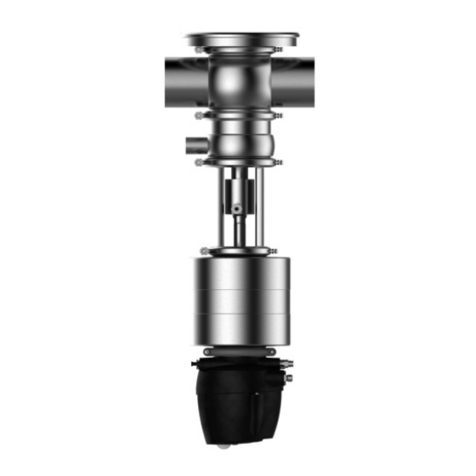
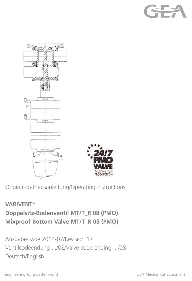
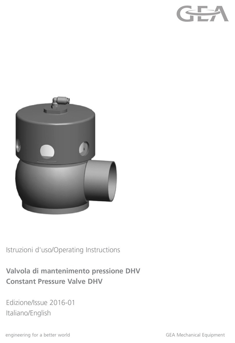
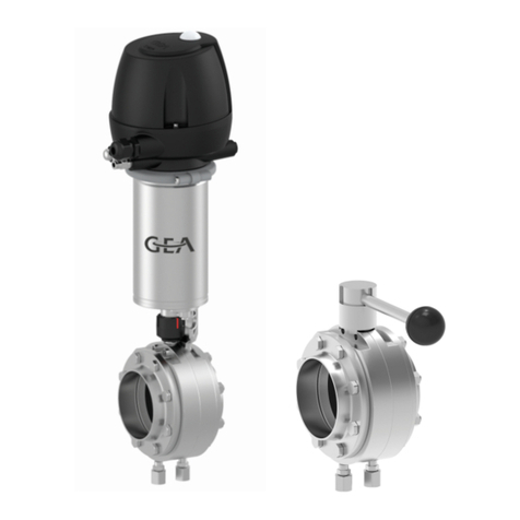
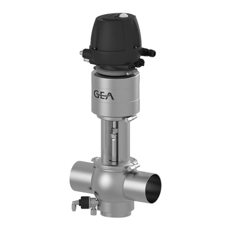
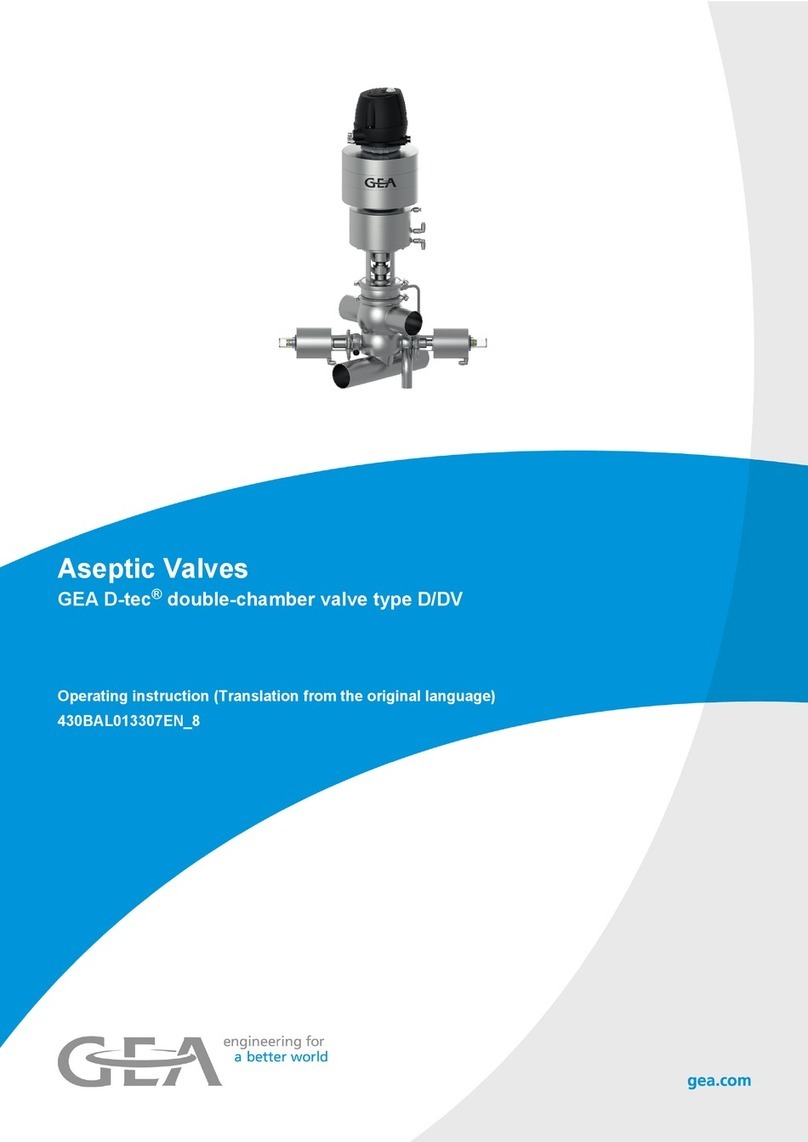
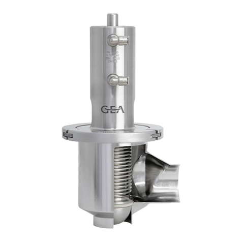
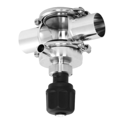
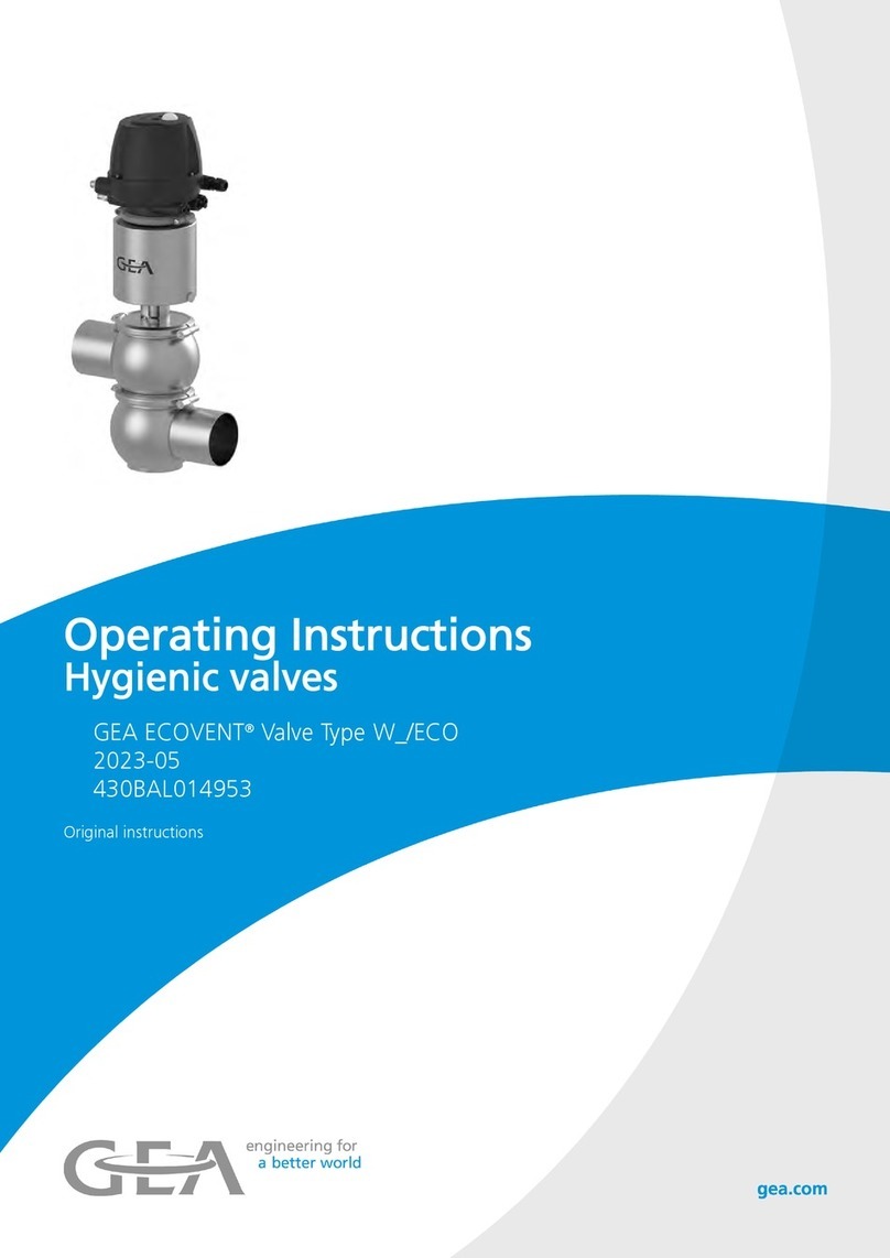
GEA ECOVENT N/W User manual

Operating Instructions
ECOVENT®
Valve N/W and N.M DN 10/15
Edition 2014-07-04
English

2
Operating Instructions · ECOVENT® Valve N/W and N.M DN 10/15
Edition 2014-07-04
Product Valve N/W and N.M DN 10/15
Document Operating Instructions
Edition 2014-07-04
English
Manufacturer GEA Tuchenhagen GmbH
Am Industriepark 2-10
D-21514 Büchen
Phone:+49 4155 49-0
Fax: +49 4155 49-2423
Mail: sales.geatuchenhage[email protected]
Web: http://www.tuchenhagen.com
These operating instructions are protected by copyright. All rights reserved. The docu-
ment may not, in whole or in part, be copied, reproduced, translated or reduced to an
electronic medium of machine-readable form without the express permission of GEA
Tuchenhagen GmbH.
Wordmarks The designations T.VIS®and ECOVENT®are protected trademarks of GEA Tuchen-
hagen GmbH.

3
Table of Contents
Notes for the Reader ...................................................................................................................................... 5
Binding Character of These Operating Instructions ......................................................................................... 5
Notes on the Illustrations .................................................................................................................................. 5
Symbols and Highlighting ................................................................................................................................. 6
Abbreviations and Terms ................................................................................................................................. 7
Safety............................................................................................................................................................... 9
Safety Note ....................................................................................................................................................... 9
Operator's Duties .............................................................................................................................................. 9
Qualification of Staff ....................................................................................................................................... 10
Supplementary Regulations ........................................................................................................................... 11
Instructions for the Safe Operation ................................................................................................................. 12
•General Principles ...................................................................................................................................... 12
•Installation .................................................................................................................................................. 12
•Commissioning/Setup Mode ...................................................................................................................... 13
•Setting into Operation ................................................................................................................................. 13
•Operation .................................................................................................................................................... 13
•Shutting Down ............................................................................................................................................ 14
•Maintenance and Repair ............................................................................................................................ 14
•Disassembly ............................................................................................................................................... 15
•Environmental Protection ........................................................................................................................... 15
•Electrical Equipment................................................................................................................................... 15
Signage .......................................................................................................................................................... 16
Residual Risk ................................................................................................................................................. 17
•Hazard Areas ............................................................................................................................................. 17
•Residual Dangers ....................................................................................................................................... 18
•Declaration of Incorporation ....................................................................................................................... 19
Intended Purpose ......................................................................................................................................... 20
Designated Use .............................................................................................................................................. 20
Requirements for the Operation ..................................................................................................................... 20
Pressure Equipment Directive ........................................................................................................................ 20
ATEX Directive ............................................................................................................................................... 20
Improper Operating Conditions ...................................................................................................................... 21
Conversion Work ............................................................................................................................................ 21
Transport and Storage................................................................................................................................. 22
Scope of Supply ............................................................................................................................................. 22
Transport ........................................................................................................................................................ 22
Storage ........................................................................................................................................................... 22
Design ........................................................................................................................................................... 23
Installation and Commissioning ................................................................................................................. 24
Notes on Installation ....................................................................................................................................... 24
Valve with Detachable Pipe Connection Elements ........................................................................................ 24
Valve with Welding Ends ................................................................................................................................ 25
Pneumatic Connections ................................................................................................................................. 26
•Air requirement ........................................................................................................................................... 26
•Establishing the hose connection ............................................................................................................... 26

4
Operating Instructions · Valve N/W and N.M DN 10/15
Edition 2014-07-04
Electrical Connections..................................................................................................................................... 27
Commissioning................................................................................................................................................ 27
Malfunctions.................................................................................................................................................. 28
Maintenance .................................................................................................................................................. 29
Inspections ...................................................................................................................................................... 29
•Product Contact Seals ................................................................................................................................ 29
•Pneumatic Connections .............................................................................................................................. 29
•Electrical Connections ................................................................................................................................ 29
Maintenance Intervals ..................................................................................................................................... 30
Removing the Valve ........................................................................................................................................ 30
Disassembling Valve N ................................................................................................................................... 31
•Removing the Control Module .................................................................................................................... 31
•Removing the Valve Insert .......................................................................................................................... 32
•Dismantling Individual Parts ........................................................................................................................ 33
•Converting the Actuator .............................................................................................................................. 34
Disassembling Valve W .................................................................................................................................. 34
•Removing the Control Module .................................................................................................................... 34
•Removing the Valve Insert .......................................................................................................................... 35
•Dismantling Individual Parts ........................................................................................................................ 36
•Converting the Actuator .............................................................................................................................. 37
Maintenance.................................................................................................................................................... 37
•Cleaning the Valve ...................................................................................................................................... 37
•Replacing Seals .......................................................................................................................................... 38
•Lubricating Seals and Threads ................................................................................................................... 40
Assembly......................................................................................................................................................... 41
Disposal .......................................................................................................................................................... 41
•General Notes ............................................................................................................................................. 41
•Valve Actuator Disposal .............................................................................................................................. 42
Technical Data............................................................................................................................................... 43
Type Plate ....................................................................................................................................................... 43
Technical Data ................................................................................................................................................ 43
Resistance of Sealing Materials ...................................................................................................................... 45
Tools ............................................................................................................................................................... 46
Lubricants........................................................................................................................................................ 46
Spare Parts Lists........................................................................................................................................... 47

5
Notes for the Reader
Notes on the Illustrations
Notes for the Reader
The present Operating Instructions are part of the user information for the valve. The
Operating Instructions contain all the information you need to transport, install, commis-
sion, operate and carry out maintenance for the valve.
Binding Character of These Operating Instructions
These Operating Instructions contain the manufacturer's instructions for the owner of the
valve and for all persons who work on or use the valve regarding the procedures to
follow.
Carefully read these Operating Instructions before starting any work on or using the
valve. Your personal safety and the safety of the valve can only be ensured if you act as
described in the Operating Instructions.
Store the Operating Instructions in such a way that it is accessible to the owner and the
operating staff during the entire life cycle of the valve. When the location is changed or
the valve is sold make sure you also provide the Operating Instructions.
Notes on the Illustrations
The illustrations in these Operating Instructions show the valve in a simplified form. The
actual design of the valve can differ from the illustration. For detailed views and dimen-
sions of the valve please refer to the design documents.

Notes for the Reader
Symbols and Highlighting
6
Operating Instructions · ECOVENT® Valve N/W and N.M DN 10/15
Edition 2014-07-04
Symbols and Highlighting
In these Operating Instructions, important information is highlighted by symbols or
special formatting. The following examples illustrate the most important types of high-
lighting.
DANGER
Warning: Fatal Injuries.
Failure to observe the warning can cause serious damage to health, or even death.
The arrow identifies a precautionary measure you have to take to avoid the hazard.
WARNING
Warning: Serious Injuries.
Failure to observe the warning note can result in serious damage to health.
The arrow identifies a precautionary measure you have to take to avoid the hazard.
CAUTION
Warning: Injuries.
Failure to observe the warning note can result in minor or moderate damage to health.
The arrow identifies a precautionary measure you have to take to avoid the hazard.
IMPORTANT NOTE
Warning: Damage to Property.
Non-observance of the warning note can cause serious damage to the valve or the
vicinity of the valve.
The arrow identifies a precautionary measure you have to take to avoid the hazard.
EXPLOSION HAZARD
Warning: Explosions.
Failure to observe the warning may result in a severe explosion.
The arrow identifies a precautionary measure you have to take to avoid the hazard.
Carry out the following steps: = Start of instructions for a task.
1. First step in a sequence of operations.
2. Second step in a sequence of operations.
Result of the previous operation.
The operation is complete, the goal has been achieved.

7
Notes for the Reader
Abbreviations and Terms
NOTE
Further useful information.
Abbreviations and Terms
Abbreviation Explanation
a/f Indicates the size of spanners
width across flats
approx. approximately
BS British Standard
bar Unit of measurement of pressure [bar]
All pressure ratings [bar/psi] stand for over pressure [barg/psig]
if this is not explicitly described differently.
Cv value flow coefficient [US gallons per minute]
1 Cv = 1,17 x Kv
°C Unit of measurement of temperature [degree Celsius]
dm3nUnit of measurement of volume [cubic decimetre]
Volume (litre) at standard temperature and pressure
DN DIN nominal width
DIN German standard issued by DIN (Deutsches Institut für Normung e.V,
German Institute for Standardization)
EN European Standard
EPDM Material designation
Short designation according to DIN/ISO 1629:
Ethylene Propylene Diene Rubber
°F Unit of measurement of temperature [degree Fahrenheit]
FKM Material designation, short designation according to DIN/ISO 1629:
Fluorine rubber
h Unit of measurement of time [hour}
HNBR Material designation
Short designation according to DIN/ISO 1629:
Hydrogenated Acrylonitrile Butadiene Rubber
IP Protection class
Inch Unit of measurement of length [inch]
Inch OD Pipe dimension acc. to British standard
(BS), Outside Diameter
Inch IPS US pipe dimension
Iron Pipe Size
ISO International standard issued by the International Organization for Standardi-
zation
kg Unit of measurement of weight [kilogram]

Notes for the Reader
Abbreviations and Terms
8
Operating Instructions · ECOVENT® Valve N/W and N.M DN 10/15
Edition 2014-07-04
kN Unit of measurement of force [kilonewton]
L Unit of measurement of volume [litre]
max. maximum
mm Unit of measurement of length [millimetre]
m Unit of measurement of length [micrometre]
Mmetric
Nm Unit of measurement of work [newton metre]
UNIT OF TORQUE 1 Nm = 0.737 lbft
Pound-Force (lb) + Feet (ft)
PA Polyamide
PE-LD Low-density polyethylene
psi Anglo-American Unit of measurement of pressure
[Pound-force per square inch]
All pressure ratings [bar/psi] stand for over pressure [barg/psig]
if this is not explicitly described differently.
SET-UP Self-learning installation
During commissioning and maintenance, the SET-UP procedure carries out
all the necessary settings for the generation of messages.
TIG Welding method
Tungsten inert gas welding
T.VIS Tuchenhagen Valve Information System
V AC Volt alternating current
V DC Volt direct current
W Unit of measurement of power [Watt]
Abbreviation Explanation

9
Safety
Operator's Duties
Safety
Safety Note
The valve is operationally reliable. It was built according to state-of-the art standards.
Nevertheless, the valve can pose dangers, especially if
•the valve is not used in accordance with its intended use,
•the valve is not used correctly,
•the valve is operated under impermissible operating conditions.
Operator's Duties
In your capacity as operator of the facility you bear a particular responsibility for the
proper and safe handling of the valve in your facility. Only use the valve when it is in
perfect condition to prevent danger to persons and property.
These Operating Instructions contain the information you and your staff need for the
safe and reliable operation during the entire service life of the valve. Be sure to read
these Operating Instructions carefully and ensure that the measures described here are
observed.
The operator's duty of care includes planning the necessary safety measures and moni-
toring that these measures are observed. The following principles apply:
•Only allow qualified staff to work on the valve.
•The operator must authorize the staff to carry out the relevant tasks.
•Working areas and the entire environment of the valve must be neat and clean.
•The staff must wear suitable work clothing and personal protective equipment. As
the operator of the facility make sure that work clothing and personal protective
equipment are used.
•Instruct the staff with regard to any properties of the product which might pose a
health risk and the preventative measures to be taken.
•Have a qualified first-aider on call during the operation, who can initiate the neces-
sary first-aid measures in case of an emergency.
•Clearly define processes, lines of authority and responsibilities associated with the
valve. Everybody must know what to do in case of an emergency. Instruct the staff
in this respect at regular intervals.
•The signs relating to the valve must always be complete and legible. Check, clean
and replace the signs as necessary at regular intervals.
NOTE
Carry out regular checks. This way you can ensure that these measures are actually
observed.

Safety
Qualification of Staff
10
Operating Instructions · ECOVENT® Valve N/W and N.M DN 10/15
Edition 2014-07-04
Qualification of Staff
This section contains information about the qualifications that staff working on the valve
must have.
Operating and maintenance staff must
•have the necessary qualification to carry out their tasks,
•be instructed with regard to possible dangers,
•know and observe the safety instructions given in the documentation.
Only allow qualified electricians to carry out work on the electrical equipment or have a
qualified electrician supervise the work.
Only allow specially trained staff to carry out any work on explosion-protected equip-
ment. When working on explosion-protected equipment observe the standards DIN EN
60079-14 for gases and DIN EN 50281-1-2 for dusts.
The following minimum qualifications are required:
•Vocational training as a specialist who can work on the valve independently.
•Sufficient instruction to work on the valve under the supervision and direction of a
qualified specialist.
Each member of staff must meet the following requirements to be allowed to work on the
valve:
•Personal qualification for the relevant task.
•Sufficient professional qualification for the relevant task.
•Instructed with regard to the function of the valve.
•Instructed with regard to the operating sequences of the valve.
•Familiar with the safety devices and their function.
•Familiar with these Operating Instructions, especially with the safety instructions and
the information which is relevant for the task on hand.
•Familiar with the basic regulations with regard to occupational health and safety and
accident prevention.
For work to be carried out on the valve the following user groups are distinguished:
User groups
Staff Qualifications
Operating staff Adequate instruction and sound knowledge in the following areas:
•Function of the valve
•Valve operating sequences
•What to do in case of an emergency
•Lines of authority and responsibilities with respect to the task.

11
Safety
Supplementary Regulations
In addition to the instructions in this documentation the following also has to be
observed:
•pertinent accident prevention regulations,
•generally accepted safety rules,
•national regulations applicable in the country of use,
•work and safety instructions applicable in the facility,
•installation and operating regulations for use in potentially explosive areas.
Maintenance staff Adequate instruction as well as sound knowledge of the design and
function of the valve.
Sound knowledge in the following areas:
•Mechanical equipment
•Electrical equipment
•Pneumatic system
Authorization with regard to safety engineering standards to carry out
the following tasks:
•Setting devices into operation
•Earthing of devices
•Marking of devices
The relevant certificates of qualification must be submitted before work
can be carried out on ATEX certified machines.
User groups (Cont.)
Staff Qualifications

Safety
Instructions for the Safe Operation
12
Operating Instructions · ECOVENT® Valve N/W and N.M DN 10/15
Edition 2014-07-04
Instructions for the Safe Operation
Dangerous situations during the operation can be avoided by safety-conscious and
proactive behaviour of the staff.
General Principles
To ensure the safe operation of the valve the following principles apply:
•The Operating Instructions must be kept ready to hand at the valve's place of use. It
must be complete and in clearly legible form.
•Only use the valve for its intended use.
•The valve must be functional and in good working order. Check the condition of the
valve before starting work and at regular intervals.
•Wear tight-fitting work clothing for all work on the valve.
•Ensure that nobody can get hurt on the parts of the valve.
•Immediately report any faults or noticeable changes on the valve to the person
responsible.
•Observe the accident prevention regulations and all local regulations.
Installation
For installation, the following principles apply:
•Only properly qualified staff is allowed to install, assemble and set the valve into
operation.
•Ensure that adequate working and traffic areas are available at the place of installa-
tion.
•Observe the maximum load-bearing capacity of the installation surface.
•Observe the transport instructions and markings on the part(s) to be transported.
•Remove any nails protruding from transport crates immediately after opening the
crate.
•Under no circumstances should anyone stand under a suspended load.
•During assembly, the valve safety devices might not be working effectively.
•Reliably secure machine parts which have already been connected against inadvert-
ently being switched on.

13
Safety
Instructions for the Safe Operation
Commissioning/Setup Mode
For commissioning, the following principles apply:
•Take protective measures against dangerous contact voltages in accordance with
pertinent regulations.
•The valve must be completely assembled and correctly adjusted. All screw connec-
tions must be securely tightened. All electrical cables must be installed correctly.
•Reliably secure machine parts which have already been connected against inadvert-
ently being switched on.
•Relubricate all lubricating points.
•Make sure lubricants are used properly.
•After conversion of the valve, residual risks must be reassessed.
Setting into Operation
For setting into operation, the following principles apply:
•Only allow properly qualified staff to set the valve into operation.
•Establish all connections correctly.
•The safety devices for the valve must be complete, fully functional and in perfect
condition. Check the function before starting any work.
•When the valve is switched on, the danger zones must be free.
•Remove any liquids that have escaped without leaving residues.
Operation
For operation, the following principles apply.
•Monitor the valve during the operation.
•Safety devices must not be changed, removed or taken out of service. Check all
safety devices at regular intervals.
•All guards and hoods must be fitted as intended.
•The place of installation of the valve must be adequately ventilated at all times.
•Structural alterations of the valve are not permitted. Immediately report any changes
on the valve to the person responsible.
•Always keep danger zones clear. Do not leave any objects in the danger zone. Only
allow persons to enter the danger zone when the machine is de-energized.
•Regularly check that all emergency stop devices are working correctly.

Safety
Instructions for the Safe Operation
14
Operating Instructions · ECOVENT® Valve N/W and N.M DN 10/15
Edition 2014-07-04
Shutting Down
For shutting down, the following principles apply:
•Switch off the compressed air.
•Switch off the valve via the main switch.
•Padlock the main switch (if fitted) in the off position to prevent it from being switched
back on. The key to the padlock must be deposited with the person responsible until
the machine is restarted.
•For longer periods of standstill, observe the storage conditions, see Storage
(Page 22).
Maintenance and Repair
Before starting any maintenance and repair work on the electrical devices of the valve,
carry out the following steps in accordance with the "5 safety rules":
•Isolate from the power supply
•Take appropriate measures to prevent switch on
•Test absence of voltage
•Earthing and short-circuiting
•Cover or safeguard any adjacent live parts.
For maintenance and repair, the following principles apply:
•Observe the intervals specified in the maintenance schedule.
•Only allow qualified staff to carry out maintenance or repair work on the valve.
•Before starting any maintenance or repair work, the valve must be switched off and
secured against being switched back on. Work may only be started once any
residual energy has been discharged.
•Block access for unauthorized persons. Put up notice signs which draw attention to
the maintenance or repair work going on.
•Do not climb on the valve. Use suitable access aids and working platforms.
•Wear suitable protective clothing.
•Only use suitable and undamaged tools to carry out maintenance work.
•When replacing parts only use approved, fully functional load lifting devices and
lifting accessories which are suitable for the intended purpose.
•Before setting the valve back into operation refit all safety devices as originally
provided in the factory. Then check that all safety devices are working correctly.
•Make sure lubricants are used properly.
•Check pipes are firmly secured, also check for leaks and damage.
•Check that all emergency stop devices are working correctly.

15
Safety
Instructions for the Safe Operation
Disassembly
For disassembly, the following principles apply:
•Only allow qualified staff to disassemble the valve.
•Before starting disassembly, the valve must be switched off and secured against
being switched back on. Work may only be started once any residual energy has
been discharged.
•Disconnect all power and utility lines.
•Markings, e.g. on lines, must not be removed.
•Do not climb on the valve. Use suitable access aids and working platforms.
•Mark the lines (if unmarked) prior to disassembly to ensure they are not confused
when re-assembling.
•Protect open line ends with blind plugs against ingress of dirt.
•Pack sensitive parts separately.
•For longer periods of standstill, observe the storage conditions, see “Storage“
(Page 22).
Environmental Protection
Harm to the environment can be avoided by safety-conscious and proactive behaviour
of the staff.
For environmental protection the following principles apply:
•Substances harmful to the environment must not be discharged into the ground or
the sewage system.
•Always observe the pertinent regulations relating to waste avoidance, disposal and
utilization.
•Substances harmful to the environment must be collected and stored in suitable
containers. Clearly mark the containers.
•Dispose of lubricants as hazardous waste.
Electrical Equipment
For all work on electrical equipment, the following principles apply:
•Access to electrical equipment should only be allowed to qualified electricians.
Always keep unattended switch cabinets locked.
•Modifications of the control system can affect the safe and reliable operation. Modifi-
cations are only permitted with the express permission of the manufacturer.
•After completion of all work, check that the protective devices are fully functional.

Safety
Signage
16
Operating Instructions · ECOVENT® Valve N/W and N.M DN 10/15
Edition 2014-07-04
Signage
Dangerous points on the valve are indicated by warning signs, prohibition signs and
mandatory signs.
The signs and notes on the valve must always be legible. Any illegible signs must be
replaced immediately.
Signs on the valve
Sign Meaning
General hazard warning
Warning Crushing
Explosive atmosphere hazard warning

17
Safety
Residual Risk
Residual Risk
Hazard Areas
Please observe the following notes:
•In the event of malfunctions, shut down the valve (disconnect from the power and air
supply) and secure it against being used.
•Never reach into the lantern (9) or the valve housing when the valve is switching.
Fingers can be crushed or cut off.
•On a spring-closing valve there is danger of injury when the clips (43) are opened
as the released spring pretension will suddenly lift the actuator. Therefore, release
the spring tension before detaching the clips by supplying the actuator with
compressed air.
•Before starting any service, maintenance or repair work, disconnect the valve from
the power supply and secure it against inadvertently being switched back on again.
•Only allow a qualified electrician to carry out any work on the electrical power
supply.
•Check the electrical equipment of the valve at regular intervals. Immediately remedy
loose connections and molten cables.
•If work on live parts cannot be avoided, call in a second person, who can operate
the main switch in case of an emergency.

Safety
Residual Risk
18
Operating Instructions · ECOVENT® Valve N/W and N.M DN 10/15
Edition 2014-07-04
Residual Dangers
Dangerous situations can be avoided by safety-conscious and proactive behaviour of
the staff and by wearing personal protective equipment.
Residual dangers on the valve and measures
Danger Cause Measure
Danger to life Inadvertent switch-on of the valve Effectively disconnect all components, effectively prevent
switch-on.
Electric power Observe the following safety rules:
1Isolate from the power supply.
2Take appropriate measures to prevent switch on.
3Test absence of voltage.
4Earthing and short-circuiting.
5Cover or safeguard any adjacent live parts.
Spring tension in the actuator Danger to life caused by compression spring in the actu-
ator. Do not open the actuator but return it to GEA Tuchen-
hagen for proper disposal.
Danger of injury Danger presented by moving or
sharp-edged parts
The operator must exercise caution and prudence.
For all work:
•Wear suitable work clothing.
•Never operate the machine if the cover panels are not
correctly fitted.
•Never open the cover panels during the operation.
•Never reach into openings.
As a precautionary measure, wear personal protective
equipment in the vicinity of the valve:
•Protective gloves
•Safety shoes
Environmental
damage
Operating materials with properties
which are harmful to the environ-
ment
For all work:
•Collect lubricants in suitable containers.
•Dispose of lubricants in accordance with the pertinent
regulations.

19
Safety
Residual Risk
Declaration of Incorporation
in accordance with the EC Machinery Directive 2006/42/EC
We herewith declare that this consignment contains the subsequently identified – but
incomplete – machine and that putting into service is not permitted until it has been estab-
lished that the machinery into which this machine is to be incorporated is in conformity with
the provisions of the EC Machinery Directive.
We declare that the incomplete machine identified here complies with the "Essential Health
and Safety Requirements" defined in Annex I, section 1 and section 2.1. The technical
documentation is compiled in accordance with Annex VII, part B. In response to a
reasoned request the relevant information will be transmitted to the appropriate national
authorities.
This declaration will become invalid if any alterations are made to the machine which have
not been agreed with us.
Büchen, 06/02/2009
Franz Bürmann i.V. Peter Fahrenbach
Managing Director Head of Development and Design
Designation of the machine: Valve N/W and N.M DN 10/15
Machine type: ECOIVENT®
Relevant EC directives: 2006/42/EC
Applicable harmonized standards: DIN EN ISO 12100

Intended Purpose
ATEX Directive
20
Operating Instructions · ECOVENT® Valve N/W and N.M DN 10/15
Edition 2014-07-04
Intended Purpose
Designated Use
Shut-off valve type N is used for opening and closing pipe sections. The medium should
preferably flow in the opening direction of the valve disk to prevent pressure hammers
when the valve is opened or closed.
Shuttle valve type W is used for change-over of streams of liquid within a section of a
pipe.
NOTE
The manufacturer will not accept any liability for damage resulting from any use of the
valve which is not in accordance with the designated use of the valve. The risk of such
misuse lies entirely with the operator of the facility.
Requirements for the Operation
The prerequisite for the reliable and safe operation of the valve is proper transportation
and storage as well as professional installation and assembly. Operating the valve within
the limits of its designated use also involves adhering to the operating, inspection and
maintenance instructions.
Pressure Equipment Directive
The valves type N and W are pressure equipment (without safety function) in the sense
of the pressure equipment directive: Directive 97/23/EC. They are classified according to
Annex II, article 3, section 3. In the event of any deviations, GEA Tuchenhagen GmbH
will supply a special Declaration of Conformity.
ATEX Directive
If valves type N and W are used in areas with a potentially explosive atmosphere, you
must absolutely comply with directive 94/9/EC with respect to all ignition hazards. The
supplementary "EX" operating instructions for ECOVENT valves must be observed.
For details regarding the marking of valves for potentially explosive areas refer to the
additional "Ex" operating instructions for ECOVENT valves.
This manual suits for next models
1
Table of contents
Other GEA Control Unit manuals

GEA
GEA T-smart 7 User manual

GEA
GEA VARIVENT C User manual

GEA
GEA Aseptomag GD User manual

GEA
GEA VARIVENT TSVN User manual

GEA
GEA VARIVENT D User manual

GEA
GEA VARIVENT T R Series User manual

GEA
GEA HRAB User manual

GEA
GEA SVAB User manual

GEA
GEA VARIVENT MT/T R 08 User manual

GEA
GEA VARIVENT T R User manual
Popular Control Unit manuals by other brands

Emerson
Emerson Fisher Vee-Ball V200U Series instruction manual

Honeywell
Honeywell Hometronic HB 05 Mounting and operation instructions

KJB Security
KJB Security DIY110 quick start guide

Burkert
Burkert 8691 operating instructions

PLEIGER ELEKTRONIK
PLEIGER ELEKTRONIK PPC-PLD-7 manual

Videx
Videx Art.2270 Technical manual