DEUTSCHFRANÇAIS
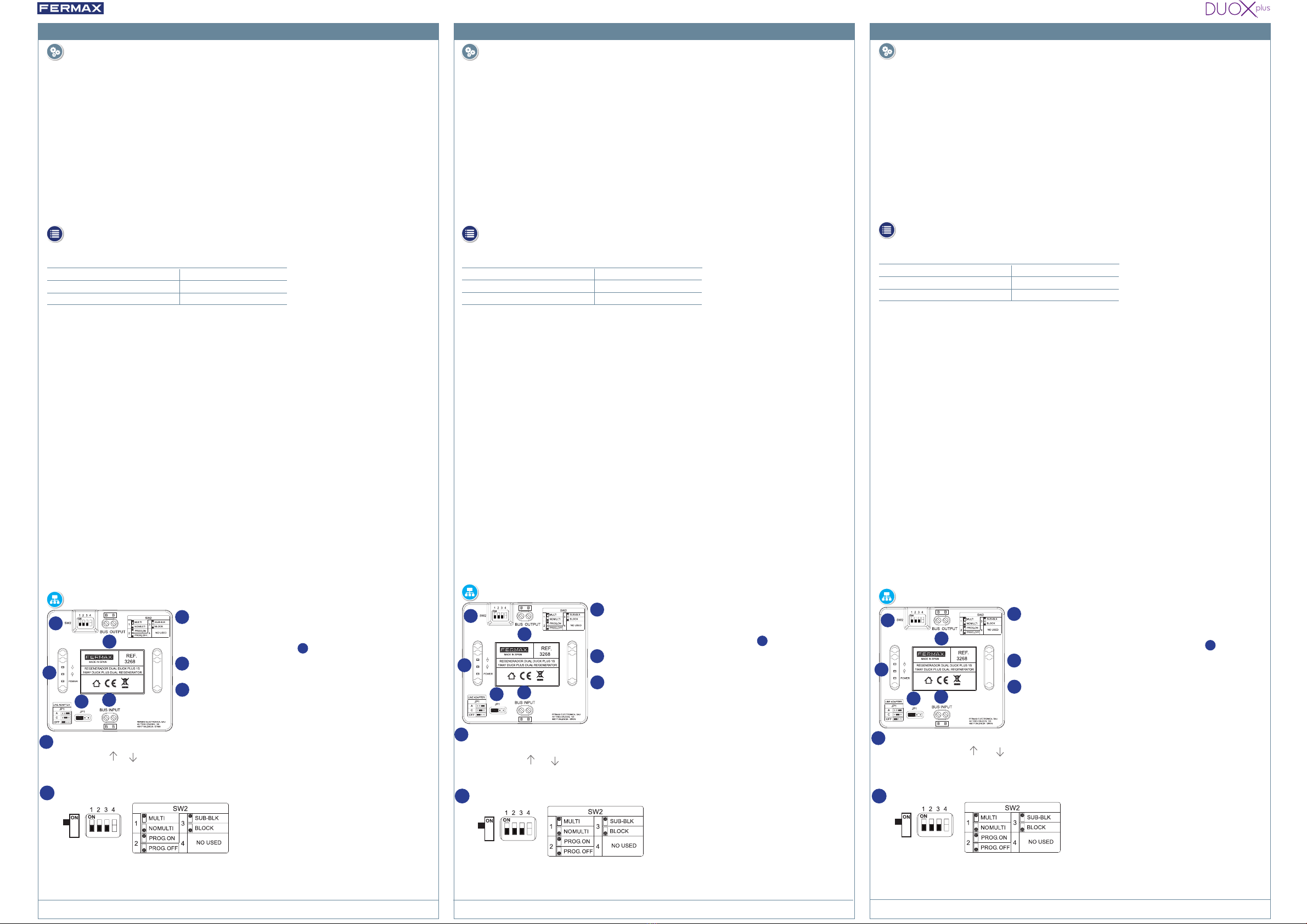
B B : Connecteur ENTRÉE DE BUS
Bus DUOX : Alimentation et données.
1
2B B : Connecteur SORTIE DE BUS
Bus DUOX : Alimentation et données.
3JP1 : Pont adaptateur de ligne (ENTRÉE DE BUS)
o À droite : Adaptateur type A.
o Au centre : Adaptateur type C.
o À gauche : OFF. Pas d'adaptation de ligne, (par défaut).
Le montage peut se faire aussi bien par xation à vis que par installation sur rail DIN.
Dimensions : 86 (H) x 89 (V) x 26 (P) mm
CARACTÉRISTIQUES TECHNIQUES
Tension alimentation 18 - 24 Vdc
Consommation au repos 1,8 W.
Consommation maximale 2,16 W.
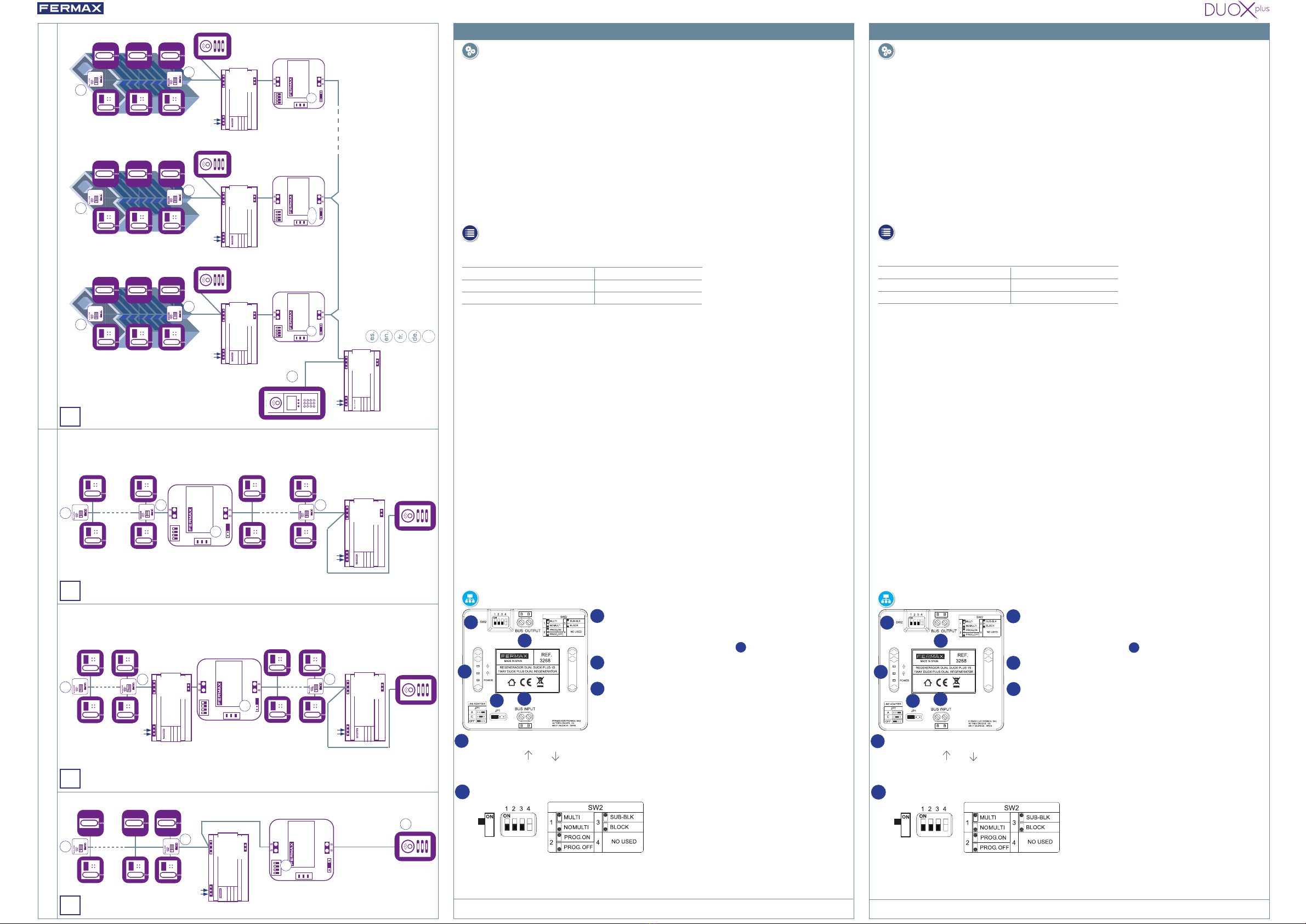
Le régénérateur dual DUOX PLUS 1S peut être utilisé aux ns suivantes :
• Augmentation de la capacité d'installation à distance et/ou de chargement des terminaux. Le
régénérateur doit être connecté à un point où le signal est acceptable (par exemple, là où un
moniteur fonctionne correctement). Voir les diagrammes 1, 2 et 3.
- 1. Extension distance platines.
- 2. Extension moniteurs.
- 3. Régénération signal.
• Isolement des sections (dérivations,...). Les deux sections entre lesquelles il est installé sont
isolées des courts-circuits, de la charge et des réexions de signaux.
•Lorsqu'il est alimenté par un port, le régénérateur permet de faire passer un courant maximum de
1,6 A vers l'autre port.
• En mode régénérateur multicanal, également établissement d’échanges simultanés dans différents
blocs. Voir Schéma 4.
FONCTIONS
Voir Livre Technique DUOX code 970122.
CAPACITÉS
PROGRAMMATION en Régénérateur multicanal du numéro de BLOC ou de SOUS-BLOC
(Adressage).
Mettre les Microrupteurs 1 (MULTI) et 2 (PROG.ON) sur ON. (Microrupteur 4 pas utilisé).
Le microrupteur 3 doit être sur ON si vous voulez programmer le SOUS-BLOCAGE et sur OFF si
vous voulez programmer le BLOCAGE.
Lorsque le régénérateur est mis sous tension (alimenté), le mode de programmation des numéros
de bloc ou de sous-bloc est activé, selon le choix du microrupteur 3. La LED POWER clignote
rapidement jusqu'à ce que le numéro de bloc/sous-bloc soit programmé via le bus.
Pour programmer l’adresse, effectuez un appel depuis la platine dudit bloc/sous-bloc, un allumage
automatique (sous-bloc ne le permet pas) ou appuyez sur F1 depuis le moniteur de ce bloc/sous-
bloc (connectés à la borne BUS OUTPUT)
Vous avez 60 secondes pour programmer votre adresse, après quoi l’interface quitte la
programmation. Dès que l'appareil est programmé avec une adresse, la LED POWER clignote à un
rythme plus lent.
Une fois la programmation terminée, mettre le microrupteur 2 sur OFF, pour éviter une
reprogrammation accidentelle.
CONNEXIONS ET TÉMOINS LUMINEUX
LED rouge "POWER" : Si elle est allumée, cela indique que l'appareil est alimenté.
LED verte « »/« » : Lorsque ce voyant est allumé, il indique le trac de données dans la
direction indiquée par la èche. Pendant un appel, les deux LED doivent clignoter. Si une des
deux ne s'allume pas, cela indique un signal insufsant dans cette direction.
4
1
2
5
4
3
5
Le bornier INPUT dispose d'une adaptation de ligne intégrée,
congurable via JP1, voir 3.
SW2 : Programmation des microrupteurs - Conguration
• 1 : ON - Régénérateur multicanal // 1 : OFF - Régénérateur (PAS multicanal).
• 2 : ON - Programmation activée. // 2 : OFF - Programmation désactivée.
• 3 : ON - Sélection de sous-blocs (pour multicanal). // 3 : OFF - Sélection de bloc (pour le multicanal).
• 4: Pas de fonctionn.
- Le régénérateur peut être alimenté par l'un ou l'autre de ses deux ports, mais pas les deux
simultanément. Si cela est fait, le régénérateur isolera le courant entre le bornier d'ENTRÉE et le
bornier de SORTIE, en s'arrêtant pour des raisons de protection.
CONNECTÉ. (Voir programmes)
Ceproduit est protégé par les brevets suivants: US 9215410, US 9762852, BE1023440) et les modèles d'utilité :
ES1187384U, ES1141495U, FR3038192, DE202016000632U1, CN205987229(U)..
B B: Anschluss BUS INPUT
Bus DUOX: Energie und Daten.
1
2B B: Anschluss BUS OUTPUT
Bus DUOX: Energie und Daten.
3JP1: Leitungsadapter-Brücke (BUS INPUT)
oder nach rechts: Anpassung Typ A.
oder zur Mitte: Anpassung Typ C.
oder nach links: OFF. Keine Leitungsanpassung, (Standard).
Die Anbringung kann durch Schraubbefestigung mit DIN-Schiene erfolgen.
Abmessungen: 86 (H) x 89 (V) x 26 (P) mm.
TECHNISCHE SPEZIFIKATIONEN
Versorgungsspannung 18 - 24 Vdc
Verbrauch im Standby 1,8 W.
Maximaler Verbrauch 2,16 W.
Der Doppelregenerator DUOX PLUS 1S kann für folgende Zwecke eingesetzt werden:
• Erhöhte Kapazität der Remote-Installation und/oder der Terminalbelastung. Der Regenerator
muss an einer Stelle angeschlossen werden, an der das Signal akzeptabel ist (z.B. wenn ein
Monitor ordnungsgemäß funktioniert). Siehe Diagramme 1, 2 und 3.
- 1. Erweiterung des Türstationabstands.
- 2. Erweiterungsmonitore.
- 3. Signalregeneration.
• Isolierung von Abschnitten (aufsteigend,...). Die beiden Abschnitte, zwischen denen es installiert
ist, sind von Kurzschlüssen, Last- und Signalreexionen isoliert.
• Bei Versorgung von einem Anschluss aus erlaubt der Regenerator einen maximalen Strom von 1,6
A, der zum anderen Anschluss geleitet werden kann.
• Auch im Modus als Mehrkanal-Regenerator, der gleichzeitige Gespräche in verschiedenen
Blöcken ermöglicht. Siehe Schema 4.
FUNKTIONEN
Siehe Fachbuch DUOX-Code. 970122.
KAPAZITÄTEN
PROGRAMMIEREN im Mehrkanal-Regenerator der BLOCK oder SUB-BLOCK-Nummer
(Adressierung).
Mikroschalter 1 (MULTI) und 2 (PROG.ON) auf ONsetzen. (Mikroschalter 4 nicht in Gebrauch).
Der Mikroschalter 3 muss auf ON stehen, wenn Sie den SUB-BLOCK programmieren wollen, und
auf OFF , wenn Sie den BLOCKprogrammieren wollen.
Beim Einschalten des Regenerators (mit Strom versorgt) wird je nach Wahl des Mikroschalters 3 in
den Programmiermodus für die Block- oder Unterblocknummer gewechselt. Die POWER-LED blinkt
schnell, bis die Block-/Teilblocknummer über den Bus programmiert ist.
Um die Adresse zu programmieren, rufen Sie sie von der Türstation dieses Blocks/Subblocks aus,
eine Selbstzündung (Subblock erlaubt das nicht) oder drücken Sie die Taste F1 von einem Monitor
dieses Blocks/Subblocks aus (der an die BUS OUTPUT-Innenstelle angeschlossen ist).
Sie haben 60 Sekunden Zeit, um Ihre Adresse zu programmieren, dann verlässt die Schnittstelle
die Programmierung. Sobald das Gerät mit einer Adresse programmiert ist, blinkt die POWER-LED
langsamer.
Sobald die Programmierung abgeschlossen ist, stellen Sie den Mikroschalter 2 auf OFF, um
versehentliches Umprogrammieren zu vermeiden.
ANSCHLÜSSE UND LEUCHTANZEIGEN
Rote „POWER“-LED: Wenn sie eingeschaltet ist, zeigt sie an, dass das Gerät mit Strom versorgt
wird.
Grüne LED „ “ / „ “:Wenn diese LED leuchtet, zeigt sie den Datenverkehr in der durch den
Pfeil markierten Richtung an. Während eines Anrufs sollten beide LEDs blinken. Wenn eine nicht
aueuchtet, weist sie auf ein unzureichendes Signal in dieser Richtung hin.
4
1
2
5
4
3
5
Die INPUT-Innenstelle hat eine eingebaute Leitungsadaption,
die über JP1 kongurierbar ist, siehe 3.
SW2: Programmierung von Mikroschaltern - Konguration
• 1: EIN - Multikanalregenerator. // 1: AUS - Regenerator (NICHT mehrkanalig).
• 2: EIN - Programmierung aktiviert. // 2: AUS - Programmierung deaktiviert.
• 3: EIN - Auswahl von Unterblöcken (für Mehrkanal). // 3: AUS - Blockauswahl (für Mehrkanal).
• 4: Keine Funktion.
- Der Regenerator kann von jedem seiner beiden Anschlüsse gespeist werden, aber nicht
von beiden gleichzeitig. Wenn dies geschieht, trennt der Regenerator den Strom zwischen der
INPUT-Innenstelle und der OUTPUT-Innenstelle und schaltet sich zum Schutz ab.
VERBUNDEN. (Siehe Schemata)
DiesesProdukt ist durch die folgenden Patente geschützt: US 9215410, US 9762852, BE1023440) und Gebrauchs-
muster: ES1187384U, ES1141495U, FR3038192, DE202016000632U1, CN205987229(U)
REGENERADOR DUAL DUOX PLUS 1S. 1W DUOX PLUS DUAL REGENERATOR. RÉGÉNÉRATEUR DUAL DUOX PLUS 1S. 1 AUSGANG DUOX PLUS DUAL REGENERATOR. REGENERATOR SYGNAŁU 1W DUOX PLUS DUAL. REF. 3268
POLSKI
B B: Złącze BUS INPUT
Magistrala Bus DUOX: Zasilanie i dane.
1
2B B: Złącze BUS OUTPUT
Magistrala Bus DUOX: Zasilanie i dane.
3JP1: Mostek adaptera liniowego (BUS INPUT)
o W prawo: Typ adaptacji A.
o W środku: Typ adaptacji C.
o W lewo: OFF (Wył.): Brak adaptacji linii (ustawienie domyślne).
Proces montażu można wykonać przy użyciu śrub lub szyny DIN.
Wymiary: 86 (wys.) x 89 (dł.) x 26 (gł.) mm
DANE TECHNICZNE
Napięcie zasilania 18 - 24 Vdc
Pobór mocy w trybie czuwania 1,8 W.
Maks. pobór mocy 2,16 W.
Podwójny regenerator sygnału DUOX PLUS 1S może być używany do następujących celów:
- Rozszerzenie instalacji zdalnej i/lub zwiększenie obciążenia terminala Regenerator należy
podłączyć w punkcie, w którym występuje stabilny sygnał (np. w miejscu, gdzie monitor działa
poprawnie). Patrz schematy 1, 2 i 3.
- 1. Zwiększenie odległości płyty.
- 2. Rozszerzenie monitora.
- 3. Regeneracja sygnału.
• Izolacja sekcji (np. pionu instalacyjnego,...). Dwie sekcje, między którymi jest instalowany
regenerator, są odizolowane od zwarć, obciążeń i odbić sygnałów.
• Podczas zasilania przy użyciu jednego portu regenerator umożliwia zasilanie drugiego portu
maksymalnym prądem 1,6 A.
• W trybie regeneratora wielokanałowego umożliwia prowadzenie równoczesnych rozmów w
różnych blokach. Patrz schemat 4.
FUNKCJE
Zob. podręcznik techniczny DUOX, kod 970122
MOŻLIWOŚCI
Tryb wielokanałowy Programowanie za pomocą regeneratora numeru BLOKU lub POD-BLOKU
(trasowanie).
Ustawić mikro-przełącznik 1 (MULTI) i 2 (PROG.ON) w pozycji ON.(Mikro-przełącznik 4 nie jest
używany).
Mikro-przełącznik 3 musi być WŁĄCZONY (ON) w przypadku programowania POD-BLOKU i WY-
ŁĄCZONY (OFF) w przypadku programowania BLOKU.
Gdy regenerator jest włączony (zasilany), uruchamiany jest ryb programowania numeru bloku lub
pod-bloku w zależności od wybranej pozycji mikro-przełącznika 3. Dioda LED zasilania będzie mi-
gać szybko do chwili zaprogramowania numeru bloku/pod-bloku.
Aby zaprogramować adres, należy wykonać połączenie z panelu w tym bloku/pod-bloku, przepro-
wadzić automatyczne włączenie (niedozwolone dla pod-bloku) lub nacisnąć przycisk F1 na monito-
rze tego bloku/pod-bloku (podłączony do zacisku BUS OUTPUT).
Czas wymagany dla przeprowadzenia programowania wynosi 60 sekund. Po upływie tego czasu
tryb programowania zostanie wyłączony. Gdy urządzenie zostanie zaprogramowane przy użyciu
adresu, dioda LED zasilania będzie migać z mniejszą częstotliwością.
Po zakończeniu programowania należy ustawić mikro-przełącznik 2 w pozycji OFF, aby nie dopu-
ścić do ponownego zaprogramowania.
POŁĄCZENIA I WSKAŹNIKI
Czerwona dioda LED zasilania „POWER”: Jeżeli jest włączona, oznacza to, że urządzenie jest zasilane.
Zielona dioda LED « » / « »: Jeżeli ta dioda LED jest włączona, oznacza to, że kierunek przesyłu
danych odbywa się w kierunku określanym strzałką. Podczas połączenia obie diody LED powinny migać.
Jeżeli określona dioda nie włączy się, będzie to oznaczać, że w tym kierunku przekazywany jest sygnał
o nieprawidłowym poziomie.
4
1
2
5
4
3
5
Terminal wejściowy (INPUT) posiada wbudowany adapter
liniowy, kongurowalny za pomocą JP1, zob. 3.
SW2: Mikro-przełączniki programujące - konguracja
• 1: ON - Regenerator wielokanałowy // 1: OFF - Regenerator (nie działa w trybie wielokanałowym).
• 2: ON - Tryb programowania włączony. // 2: OFF - Tryb programowania wyłączony.
• 3: ON - Wybór pod-bloku (dla trybu wielokanałowego). // 3: OFF - Wybór bloku (dla trybu wielokanałowego).
• 4: Brak funkcji.
- Regenerator może być zasilany przy użyciu dowolnego z dwóch dostępnych portów, ale nie
przy użyciu obu portów równocześnie. W takim przypadku regenerator odetnie prąd między
terminalem wejściowym a terminalem wyjściowym wyłączając je w celu ochrony.
PODŁĄCZONY (patrz schematy)
Ten produkt jest chroniony następującymi patentami: US 9215410, US 9762852, BE1023440) i wzorami użytkowymi:
ES1187384U, ES1141495U, FR3038192, DE202016000632U1, CN205987229(U)