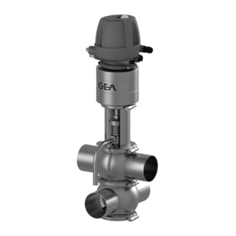
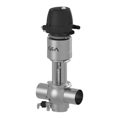
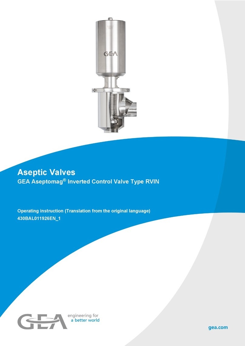
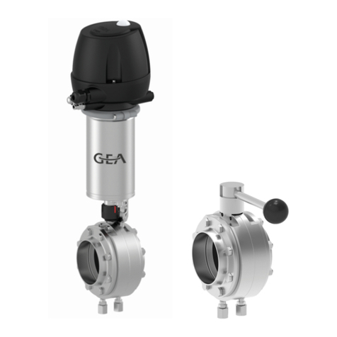
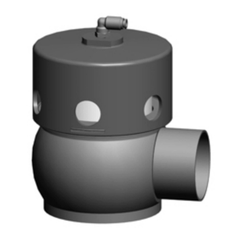
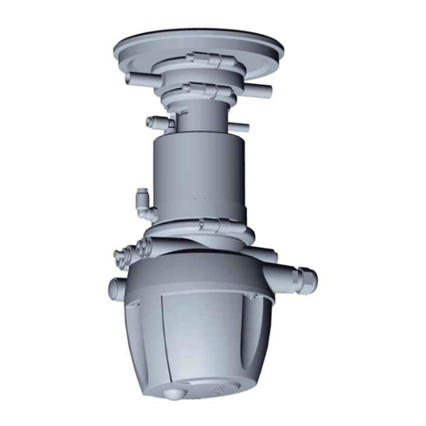
GEA VARIVENT T R User manual

Original-Betriebsanleitung/Operating Instructions
VARIVENT®Doppelsitz-Bodenventil T_R / T_RL / T_RC
VARIVENT®Mixproof Bottom Valve T_R / T_RL / T_RC
Ausgabe/Issue 2016-09
Deutsch/English
GEA Mechanical Equipmentengineering for a better world

2016-09 · Doppelsitz-Bodenventil T_R / T_RL / T_R / Mixproof Bottom Valve T_R / T_RL / T_RC

Inhalt
Wichtige Abkürzungen und Begriffe .................... 2
Sicherheitshinweise................................................. 4
Bestimmungsgemäße Verwendung .................. 4
Personal................................................................ 4
Umbauten, Ersatzteile, Zubehör ........................ 4
Allgemeine Vorschriften .................................... 4
Kennzeichnung von Sicherheitshinweisen in
der Betriebsanleitung.......................................... 5
Weitere Hinweiszeichen...................................... 5
Besondere Gefahrenstellen ................................ 6
Verwendungszweck ................................................ 7
Transport und Lagerung ........................................ 7
Lieferung prüfen ................................................ 7
Gewichte .............................................................. 7
Transport .............................................................. 8
Lagerung .............................................................. 8
Aufbau und Funktion ............................................ 9
Aufbau ................................................................ 9
Funktion ............................................................ 12
Einbau und Betrieb................................................ 14
Einbaulage ........................................................ 14
Steuerkopf ........................................................ 14
Gehäuseanschluss in den Tank einschweißen.. 15
Gehäuse in die Rohrleitung einschweißen ...... 16
Pneumatischer Anschluss .................................. 17
Verschlauchungsplan Steuerkopf T.VIS ............ 18
Verschlauchungsplan ohne Steuerkopf ............19
Elektrischer Anschluss........................................ 21
Inbetriebnahme ................................................ 21
Reinigung und Passivierung ................................ 22
Reinigung .......................................................... 22
Passivierung ...................................................... 23
Störung, Ursache, Abhilfe .................................... 25
Instandhaltung ...................................................... 26
Inspektionen ...................................................... 26
Instandhaltungsintervalle ................................ 26
Vor der Demontage .......................................... 27
Ventil T_RL und T_RC demontieren ................ 28
Ventil T_R demontieren .................................... 32
Wartung ............................................................ 34
Ventil T_RL und T_RC montieren...................... 37
Ventil T_R montieren ........................................ 41
Hub prüfen ........................................................ 42
Technische Daten .................................................. 44
Rohrenden – VARIVENT®-System ...................... 45
Reinigungsanschluss ........................................ 46
Beständigkeit der Dichtungswerkstoffe .......... 46
Werkzeugliste / Schmierstoff............................ 48
Anhang
Ersatzteillisten Ventile T_R u. T_RL u.T_RC
Ersatzteilliste / Schweißanweisung des Herstellers
Konformitätserklärung
Contents
Important Abbreviations and terms ...................... 2
Safety Instructions .................................................. 4
Designated Use.................................................... 4
Personnel.............................................................. 4
Modifications, spare parts, accessories .............. 4
General instructions ............................................ 4
Marking of safety instructions in the operating
manual ................................................................ 5
Further symbols .................................................. 5
Special hazardous spots ...................................... 6
Designated Use........................................................ 7
Transport and Storage ............................................ 7
Checking the consignment ................................ 7
Weights ................................................................ 7
Transport .............................................................. 8
Storage ................................................................ 8
Design and Function .............................................. 9
Design .................................................................. 9
Function.............................................................. 12
Assembly and Operation ...................................... 14
Installation position .......................................... 14
Control module.................................................. 14
Welding the housing connection into the tank 15
Welding the housing into the pipe .................... 16
Pneumatic connections .................................... 17
Hosing diagramm Control module T.VIS.......... 18
Hosing diagramm withoutControl module .... 20
Electrical connections........................................ 21
Commissioning .................................................. 21
Cleaning and passivation...................................... 22
Cleaning ............................................................ 22
Passivation.......................................................... 23
Malfunction, Cause, Remedy................................ 25
Maintenance .......................................................... 26
Inspections.......................................................... 26
Maintenance intervals ...................................... 26
Prior to dismantling the valve .......................... 27
Dismantling the valve T_RL and T_RC.............. 28
Dismantling the valve T_R .............................. 32
Maintenance ...................................................... 34
Mounting the valve T_RL and T_RC ................ 37
Mounting the valve T_R.................................... 41
Checking the valve stroke ................................ 42
Technical Data........................................................ 44
Pipe ends – VARIVENT®system.......................... 45
CIP Connection .................................................. 46
Resistance of the sealing material.................... 47
List of tools / Lubricant .................................... 48
Annex
Spare parts lists valves T_R and T_RL and T_RC
Spare parts list / Manufacturer’s Welding
Instructions
Conformity Declaration
2016-09 · Doppelsitz-Bodenventil T_R / T_RL / T_R / Mixproof Bottom Valve T_R / T_RL / T_RC 1

2016-09 · Doppelsitz-Bodenventil T_R / T_RL / T_R / Mixproof Bottom Valve T_R / T_RL / T_RC
2
Wichtige Abkürzun-
gen und Begriffe
BS Britischer Standard
bar Maßeinheit für den Druck
Alle Druckangaben [bar/psi] stehen für
Überdruck [barg/psig] soweit dies nicht
explizit anders beschrieben ist.
ca. cirka
°C Maßeinheit für die Temperatur
Grad Celsius
dm3nMaßeinheit für das Volumen
Kubikdezimeter
Normvolumen (Normliter)
1dm
3n= 1 ln≈ 61 inch3
DN DIN-Nennweite
DIN Deutsche Norm des
DIN Deutschen Institut für Normung e.V.
EN Europäische Norm
EPDM Materialangabe
Kurzbezeichnung nach DIN/ISO 1629
Ethylen-propylen-Dien-Kautschuk
°F Maßeinheit für die Temperatur
Grad Fahrenheit
FKM Materialangabe
Kurzbezeichnung nach DIN/ISO 1629
Fluor-Kautschuk
h Maßeinheit für die Zeit
Stunde
HNBR Materialangabe
Kurzbezeichnung nach DIN/ISO 1629
Hydrierter Acrylnitril-Butadien-Kautschuk
IP Schutzart
ISO Internationaler Standard der
International Organization for
Standardization
kg Maßeinheit für das Gewicht
Kilogramm
kN Maßeinheit für die Kraft
Kilonewton
Kv-Wert Durchflusskoeffizient [m³/s]
1 KV = 0,86 x Cv
Important Abbrevia-
tions and Terms
BS British standard
bar Unit of measure for pressure
All pressure ratings [bar/psi] stand for
over pressure [barg/psig] if this is not explicitly
described differently.
approx. approximately
°C Unit of measure for temperature
degrees centigrade
dm3nUnit of measure for volume
cubic decimetre
Volume (litre) under standard conditions
1dm
3n= 1 ln≈ 61 inch3
DN DIN nominal width
DIN Deutsche Norm (German standard)
DIN Deutsches Institut für Normung e.V.
(German institut for Standardization)
EN European standard
EPDM Material designation
Short designation acc. to DIN/ISO 1629
Ethylene propylene diene (monomer) rubber
°F Unit of measure for temperature
degrees Fahrenheit
FKM Material designation
Short designation acc. to DIN/ISO 1629
Fluorine rubber
h Unit of measure for time
hour
HNBR Material designation
Short designation acc. to DIN/ISO 1629
Hydrated acrylonitrile butadiene rubber
IP Protection class
ISO International standard of the
International Organization for
Standardization
kg Unit of measure for weight
kilogram
kN Unit of measure for force
kilo Newton
Cv-Wert flow coefficient [US gallons per minute]
1 Cv = 1,17 x Kv

2016-09 · Doppelsitz-Bodenventil T_R / T_RL / T_R / Mixproof Bottom Valve T_R / T_RL / T_RC 3
l Maßeinheit für das Volumen
Liter
max. maximal
mm Maßeinheit für die Länge
Millimeter
μm Maßeinheit für die Länge
Mikrometer
M metrisch
Nm Maßeinheit für die Arbeit
Newtonmeter
Angabe für das Drehmoment
1 Nm = 0,737 lb.ft.
Pound-Force/Pfund-Kraft (lb) + Feet/Fuß (ft)
PA Polyamid
PE-LD Polyethylen niedriger Dichte
PTFE Polytetrafluorethylen
psi Maßeinheit für den Druck
Alle Druckangaben [bar/psi] stehen für
Überdruck [barg/psig] soweit dies nicht
explizit anders beschrieben ist.
SET-UP selbstlernende Installation
Die SET-UP Prozedur führt bei Inbetrieb-
nahme und Wartung alle erforderlichen Ein-
stellungen für die Generierung von
Meldungen durch.
SW Angabe für die Größe der Werkzeugschlüssel
Schlüsselweite
s. Kap. siehe Kapitel
s. Abb. siehe Abbildung
T.VIS®Tuchenhagen Ventil Informations-
System
V DC Volt direct current = Gleichstrom
V AC Volt alternating current = Wechselstrom
W Maßeinheit für die Leistung
Watt
WIG Schweißverfahren
Wolfram-Inertgas-Schweißen
Zoll Maßeinheit für die Länge
im englische Sprachraum
Zoll OD Rohrabmessung nach Britischem Standard
(BS), Outside Diameter
Zoll IPS amerikanische Rohrabmessung
Iron Pipe Size
l Unit of measure for volume
litre
max. maximum
mm Unit of measure for length
millimetre
μm Unit of measure for length
micrometre
M metric
Nm Unit of measure for work
Newton metre
Unit for torque
1 Nm = 0.737 lb.ft.
Pound-Force (lb) + Feet (ft)
PA Polyamide
PE-LD Polyethylene low density
PTFE Polytetrafluoroethylene
psi Unit of measure for pressure
All pressure ratings [bar/psi] stand for
over pressure [barg/psig] if this is not explicitly
described differently.
SET-UP Self-learning installation
For commissioning and maintenance the
SET-UP procedure carries out all necessary
settings for the generation of messages.
Size Size of spanners
(width across flats)
see Chapt. see Chapter
s. ill. see illustration
T.VIS®Tuchenhagen Valve Information System
V DC Volt direct current
V AC Volt alternating current
W Unit of measure for
Watt
TIG Welding method
tungsten inert-gas welding
Inch Unit of measure for length
in English-speaking countries
Inch OD Pipe dimension acc. to British standard
(BS), Outside Diameter
Inch IPS US pipe dimension
Iron Pipe Size

2016-09 · Doppelsitz-Bodenventil T_R / T_RL / T_R / Mixproof Bottom Valve T_R / T_RL / T_RC
4
Sicherheitshinweise
Bestimmungsgemäße
Verwendung
Das Ventil ist nur für den beschriebenen Verwendungs-
zweck bestimmt. Jeder darüber hinausgehende
Gebrauch gilt als nicht bestimmungsgemäß. Für daraus
resultierende Schäden haftet Tuchenhagen nicht; das
Risiko dafür trägt allein der Betreiber.
Voraussetzungen für einen einwandfreien, sicheren
Betrieb des Ventils sind sachgemäßer Transport und
Lagerung sowie fachgerechte Aufstellung und Montage.
Zur bestimmungsgemäßen Verwendung gehört auch das
Einhalten der Betriebs-, Wartungs- und Instandhaltungs-
bedingungen.
Personal
Das Bedien- und Wartungspersonal muss die für diese
Arbeiten entsprechende Qualifikation aufweisen. Es
muss eine spezielle Unterweisung über auftretende
Gefahren erhalten und muss die in der Dokumentation
erwähnten Sicherheitshinweise kennen und beachten.
Arbeiten an der elektrischen Anlage nur von Elektro-
Fachpersonal durchführen lassen.
Umbauten, Ersatzteile,
Zubehör
Eigenmächtige Umbauten und Veränderungen, die die
Sicherheit des Ventils beeinträchtigen, sind nicht gestat-
tet. Schutzeinrichtungen dürfen nicht umgangen, eigen-
mächtig entfernt oder unwirksam gemacht werden.
Nur Originalersatzteile und vom Hersteller zugelasse-
nes Zubehör verwenden.
Allgemeine Vorschriften
Der Anwender ist verpflichtet, das Ventil nur im ein-
wandfreien Zustand zu betreiben.
Neben den Hinweisen in dieser Dokumentation gelten
selbstverständlich
– einschlägige Unfallverhütungsvorschriften
– allgemein anerkannte sicherheitstechnische Regeln
– nationale Vorschriften des Verwenderlandes
– betriebsinterne Arbeits- und Sicherheitsvorschriften.
– Einbau- und Betriebsvorschriften für die Verwendung
im Ex-Bereich.
Safety Instructions
Designated use
The valve is designed exclusively for the purposes de-
scribed below. Using the valve for purposes other than
those mentioned is considered contrary to its designated
use. Tuchenhagen cannot be held liable for any damage
resulting from such use; the risk of such misuse lies
entirely with the user.
The prerequisite for the reliable and safe operation of
the valve is proper transportation and storage as well as
competent installation and assembly.
Operating the valve within the limits of its designated
use also involves observing the operating, inspection
and maintenance instructions.
Personnel
Personnel entrusted with the operation and mainte-
nance of the valve must have the suitable qualification
to carry out their tasks. They must be informed about
possible dangers and must understand and observe the
safety instructions given in the relevant manual. Only
allow qualified personnel to make electrical connections.
Modifications, spare parts,
accessories
Unauthorized modifications, additions or conversions
which affect the safety of the valve are not permitted.
Safety devices must not be bypassed, removed or made
inactive.
Only use original spare parts and accessories recom-
mended by the manufacturer.
General instructions
The user is obliged to operate the valve only when it is
in good working order.
In addition to the instructions given in the operating
manual, please observe the following:
– relevant accident prevention regulations
– generally accepted safety regulations
– regulations effective in the country of installation
– working and safety instructions effective in the user's
plant.
– Installation and operating instructions within poten-
tially explosive areas

2016-09 · Doppelsitz-Bodenventil T_R / T_RL / T_R / Mixproof Bottom Valve T_R / T_RL / T_RC
Symbol Signalwort Bedeutung
GEFAHR Unmittelbar drohende
Gefahr, die zu schweren
Körperverletzungen
oder Tod führen kann.
VORSICHT Gefährliche Situation, die
zu leichten Körperverlet-
zungen oder Sachschäden
führen kann.
Bei Arbeiten in explosions-
gefährdeten Bereichen
unbedingt die Hinweise
zur Inbetriebnahme und
Instandhaltung beachten.
Weitere Hinweiszeichen
Zeichen Bedeutung
• Arbeits- oder Bedienschritte, die in
der aufgeführten Reihenfolge ausge-
führt werden müssen.
✗Information zur optimalen Verwen-
dung des Ventils
– allgemeine Aufzählung
Kennzeichnung von
Sicherheitshinweisen in
der Betriebsanleitung
Die speziellen Sicherheitshinweise stehen direkt vor der
jeweiligen Handlungsanweisung. Sie sind hervorgeho-
ben durch ein Gefahrensymbol und ein Signalwort.
Texte neben diesen Symbolen unbedingt lesen und
beachten, erst danach weitergehen im Text und mit der
Handhabung des Ventils.
5
Marking of safety
instructions in the
operating manual
Special safety instructions are given directly before the
operating instructions. They are marked by the follow-
ing symbols and associated signal words.
It is essential that you read and observe the texts belong-
ing to these symbols before you continue reading the
instructions and handling the valve.
Symbol Signal word Meaning
DANGER Imminent danger, which
may cause severe bodily
injury or death.
CAUTION Dangerous situation,
which may cause slight
injury or damage to
material.
When working in
potentially explosive
atmospheres, strictly
observe the instructions
for commissioning and
maintenance
Further symbols
Symbol Meaning
• Process / operating steps which
must be performed in the specified
order.
✗Information as to the optimum
use of the valve.
– General enumeration

6
Besondere
Gefahren-
stellen
GEFAHR
Bei Funktionsstörungen
Ventil außer Betrieb
nehmen (von der Strom-
und Luftzufuhr abtren-
nen) und gegen Wieder-
verwendung sichern.
Störung umgehend besei-
tigen.
Nie in die Laterne (2) und
das Ventilgehäuse (3) grei-
fen.
Beim Lösen der Klemm-
verbindung (1) des nicht
angesteuerten Ventils
(Version federschließend)
besteht Verletzungsgefahr,
da die freigesetzte Feder-
vorspannung den Antrieb
sprungartig anhebt.
Vor dem Lösen der
Klemmverbindung (1)
deshalb Federspannung
aufheben
– mit Notluftbetätigung
oder
– durch Belüften des
Antriebs mit Druckluft.
VORSICHT
Die Gehäusestutzen sind
sehr scharfkantig. Beim
Transport und der Monta-
ge des Ventils unbedingt
geeignete Schutzhand-
schuhe tragen.
Beim Transport des Ven-
tils unbedingt den Steuer-
kopf und die Schaltstange
herausschrauben und das
Ventil mit eingeschraubter
Ringschraube (4), Sach-
Nr. 221-104.98, anheben.
Special
hazardous
spots
DANGER
In the event of malfunc-
tions set the valve out of
operation (disconnect the
valve from the power and
the air supply) and secure
it against reactivation.
Immediately rectify the
fault.
Never put your hand into
the lantern (2) or into the
valve housing (3).
When the clamp joints (1)
of the non-actuated valve
(spring-closing action) are
detached, there is danger
of injury, since the
released spring pressure
suddenly lifts the actua-
tor.
Therefore, prior to detach-
ing the clamp joints (1),
release the spring
tension:
– through the pneumatic
emergency switchbar.
– by pressurizing the
actuator with com-
pressed air.
CAUTION
Housing sockets have
very sharp edges. There-
fore wear suitable protec-
tion gloves during trans-
port or installation of the
valve.
For transportation of the
valve, it is imperative to
remove the control top
and the valve stem and to
use the screwed-in eye
bolt (4), part no. 221-
104.98 for lifting the
valve.
2016-09 · Doppelsitz-Bodenventil T_R / T_RL / T_R / Mixproof Bottom Valve T_R / T_RL / T_RC
2
1
1
1
1
3
4

7
2016-09 · Doppelsitz-Bodenventil T_R / T_RL / T_R / Mixproof Bottom Valve T_R / T_RL / T_RC
Beim Schalten des Ventils sowie bei der Ventilsitzreini-
gung oder einem Dichtungsdefekt tritt Reinigungsmedi-
um aus dem Leckageauslauf aus. Dieses ist in einem
geeignetem Auffangbehältnis wie zum Beispiel einem
Trichter oder einer Leckagewanne aufzufangen und
gesichert abzuführen. Es sind die Anweisungen in den
Sicherheitsdatenblätter der Reinigungsmittelhersteller
zu beachten.
Verwendungszweck
Die Doppelsitz-Bodenventile T_R, T_RL und T_RC wer-
den zum vermischungssicheren Absperren von hoch-
wertigen, nichtabrasiven Produkten an Tankausläufen
eingesetzt.
Die Doppelsitz-Bodenventile T_R, T_RL und T_RC sind
druckhaltende Ausrüstungsteile (ohne Sicherheitsfunk-
tion) im Sinne der Richtlinie über Druckgeräte: Richtli-
nie 97/23/EG. Sie sind eingestuft nach Anhang II in
Artikel 3, Absatz 3. Bei Abweichungen davon wird eine
spezielle Konformitätserklärung mitgeliefert.
Transport und
Lagerung
Lieferung prüfen
Beim Empfang des Ventils prüfen, ob
– Typen- und Seriennummer auf dem Typenschild mit
den Angaben der Bestell- und Lieferunterlagen über-
einstimmen,
– die Ausrüstung vollständig ist und alle Teile in ein-
wandfreiem Zustand vorliegen.
Äußerlich erkennbare Transportschäden und/oder feh-
lende Kolli sind beim anliefernden Spediteur sofort auf
dem Frachtbrief anzugeben. Die Spedition ist vom Emp-
fänger sofort schriftlich in Regress zu nehmen, und
Tuchenhagen ist über den Vorgang zu informieren.
Nicht sofort erkennbare Transportschäden sind inner-
halb von 6 Tagen beim Spediteur zu reklamieren.
Später beanstandete Schäden gehen zu Lasten des Emp-
fängers.
Gewichte
Baugröße Gewicht (kg)
Ventil T_R Ventil T_RL/T_RC
DN 25, 1" - ca. 16,0
DN 40, 1,5" ca. 15,3 ca. 17,5
DN 50, 2" ca. 15,6 ca. 17,7
DN 65, 2,5" ca. 25,4 ca. 32,5
DN 80, 3" ca. 28,7 ca. 41,2
DN 100, 4" ca. 37,1 ca. 47,0
DN 125 ca. 55,7 ca. 68,8
DN 150, 6" ca. 71,9 ca. 80,1
When the valve switches, when the valve seat is cleaned
or if a seal is defective, cleaning medium escapes from
the leakage outlet. This leakage must be collected in a
suitable container, e.g. a funnel or a drip pan, and
removed in a controlled manner. Observe the instruc-
tions in the safety data sheets issued by the detergent
manufacturers.
Designated Use
The Mixproof Bottom Valves type T_R, T_RL and T_RC
are used for the mixproof shut-off of highly valuable,
non-abrasive products at tank outlets.
Mixproof Bottom Valves type T_R, T_RL and T_RC are
pressure keeping equipment parts (without safety func-
tion) in the sense of the pressure equipment guideline
97/23/EC. They are classified according to Appendix II
in Article 3, Section 3. In case of deviations thereof, a
separate Declaration of Conformity will be handed out
together with the equipment.
Transport and
Storage
Checking the consignment
Upon receipt of the valve check whether the
– type and serial number on the type plate correspond
to the data in the order and delivery documents and
– the equipment is complete and all components are in
good order.
The forwarding agent must immediately be notified of
any transport damage detectable from the outside
and/or missing packages (confirmation on the consign-
ment note). The consignee shall take recourse against
the forwarding agent immediately in writing and
inform Tuchenhagen accordingly.
Transport damages which cannot be recognized imme-
diately shall be brought to the forwarder´s notice within
6 days. Later claims on damages shall be born by the
consignee.
Weights
Size Weight (kg)
Valve T_R Valve T_RL/T_RC
DN 25, 1" - approx. 16,0
DN 40, 1,5" approx. 15.3 approx. 17.5
DN 50, 2" approx. 15.6 approx. 17.7
DN 65, 2,5" approx. 25.4 approx. 32.5
DN 80, 3" approx. 28.7 approx. 41.2
DN 100, 4" approx. 37.1 approx. 47.0
DN 125 approx. 55.7 approx. 68.8
DN 150, 6" approx. 71,9 approx. 80,1

82016-09 · Doppelsitz-Bodenventil T_R / T_RL / T_R / Mixproof Bottom Valve T_R / T_RL / T_RC
Transport
GEFAHR
Die Verpackungseinheiten/Ventile dürfen nur mit dafür
geeigneten Hebezeugen und Anschlagmitteln transpor-
tiert werden. Die auf der Verpackung angebrachten Bild-
zeichen beachten.
Ventil vorsichtig transportieren, um Schäden durch
Gewalteinwirkung oder unvorsichtiges Be- und Entla-
den zu verhindern. Die Kunststoffe der Anschlussköpfe
sind bruchempfindlich.
Beim Transport des Ventils unbedingt den Steuerkopf
und die Schaltstange herausschrauben und das Ventil
mit eingeschraubter Ringschraube, Sach-Nr. 221-104.98,
anheben.
Lagerung
Die Ventile, Ventileinsätze oder Ersatzteile sollten tro-
cken, vibrations- und staubfrei zur Vermeidung von
Beschädigungen möglichst in der Originalverpackung
gelagert werden.
War das Ventil beim Transport oder bei der Lagerung
Temperaturen ≤ 0°C ausgesetzt, muss es zum Schutz
vor Beschädigungen trocken zwischenlagern. Wir emp-
fehlen vor dem Handling (Demontage der Gehäuse /
Ansteuern der Antriebe) eine Lagerung von 24 h bei
einer Temperatur ≥ 5 °C, damit sich die möglicherweise
aus dem Kondenswasser entstandenen Eiskristalle
zurückbilden können.
Transport
DANGER
For transport of the package units/valves only use suit-
able lifting gears and slings. Observe the instruction
symbols on the package and on the valve.
Handle the valve with care to avoid damage caused by
shock or careless loading and unloading.
The plastic materials of the control tops are susceptible
to breaking.
For the transportation the valve, it is imperative to
remove the control top and the valve stem and to use
the screwed-in eye bolt, part no. 221-104.98 for lifting
the valve.
Storage
Valves, valve inserts or spare parts should be stored in
a dry place, free of vibrations and dust. To avoid dam-
age, leave the components in their original packaging if
possible.
In the case that during transport or storage the valve
was exposed to temperatures ≤ 0°C, it must be stored
in a dry place against damage.
We recommend, prior to any handling (dismounting
the housings / activation of actuators) an intermediate
storage of 24 h at a temperature of ≥ 5 °C so that any ice
crystals formed by condensation water may melt.

9
2016-09 · Doppelsitz-Bodenventil T_R / T_RL / T_R / Mixproof Bottom Valve T_R / T_RL / T_RC
1 Steuerkopf
2 Elektroanschluss für
Versorgung
3 Luftanschluss für
Versorgung
4 Antrieb
5 Laterne
6 Reinigungshaube
7 Doppelteller
8 Ventilteller
✗Gehäusekonfiguratio-
nen siehe Ersatzteil-
zeichnung
1 control top
2 electrical connection
for supply
3 pneumatic connection
for supply
4 actuator
5 lantern
6 CIP bonnet
7 double-disk
8 valve disk
✗For housing configura-
tions see spare parts
drawing.
1
2
3
4
5
6
7
8
Aufbau und Funktion
Aufbau
Es gibt 3 Ausführungsvarianten:
T_R ohne Liftantrieb und mit Reinigungsanschluss
T_RL mit Liftantrieb und mit Reinigungsanschluss
T_RC mit Liftantrieb und ohne Reinigungsanschluss
Doppelsitz-Bodenventil T_R
– ohne Liftantrieb
– mit Reinigungsanschluss
(Reinigungshaube)
Design and Function
Design
There are 3 design variants:
T_R without lifting actuator and with CIP connection
T_RL with lifting actuator and with CIP connection
T_RC with lifting actuator and without CIP connection
Mixproof Bottom Valve T_R
– without lifting actuator
– with CIP connection
(CIP bonnet)

1 Steuerkopf
2 Elektroanschluss für
Versorgung
3 Luftanschluss für
Versorgung
4 Antrieb
5 Liftantrieb
6 Laterne
7 Reinigungsanschluss
8 Doppelteller
9 Ventilteller
10 Reinigungsdüse
✗Gehäusekonfiguratio-
nen siehe Ersatzteil-
zeichnung
1 control top
2 electrical connection
for supply
3 pneumatic connection
for supply
4 actuator
5 lifting actuator
6 lantern
7 CIP connection
8 double disk
9 valve disk
10 cleaning nozzle
✗For housing configura-
tions see spare parts
drawing.
1
2
3
4
5
6
7
8
9
10
Doppelsitz-Bodenventil T_RL
– mit Liftantrieb
– mit Reinigungsanschluss
Mixproof Bottom Valve T_RL
– with lifting actuator
– with CIP connection
2016-09 · Doppelsitz-Bodenventil T_R / T_RL / T_R / Mixproof Bottom Valve T_R / T_RL / T_RC
10

1 Steuerkopf
2 Elektroanschluss
Versorgung
3 Luftanschluss
Versorgung
4 Antrieb
5 Liftantrieb
6 Laterne
7 Leckanzeiger
8 Doppelteller
9 Ventilteller
10 Schnappdichtung mit
O-Ring
✗Gehäusekonfiguratio-
nen siehe Ersatzteil-
zeichnung
1 control top
2 electrical connection
for supply
3 pneumatic connection
for supply
4 actuator
5 lifting actuator
6 lantern
7 leakage indicator
8 double-disk
9 valve disk
10 snap seal with O-ring
✗For housing configura-
tions see spare parts
drawing.
1
2
3
4
5
6
7
8
9
Doppelsitz-Bodenventil T_RC
– mit Liftantrieb
– ohne Reinigungsanschluss
(mit Leckanzeiger)
Mixproof Bottom Valve T_RC
– with lifting actuator
– without CIP connection
(with leakage indicator)
10
2016-09 · Doppelsitz-Bodenventil T_R / T_RL / T_R / Mixproof Bottom Valve T_R / T_RL / T_RC 11

Reinigung
Über einen separaten, in
der Laterne angeordneten
Reinigungsanschluss (1)
wird dem Leckage-
Ablaufsystem Reinigungs-
flüssigkeit zugeführt.
Die Reinigungsflüssigkeit
wird im Hohlraum zwi-
schen den beiden Ventil-
tellern über eine Reini-
gungsdüse (2) verspritzt.
Sie fließt danach drucklos
über den Doppelteller (3)
und durch das Ablaufrohr
(4) des Leckagegehäuses
ins Freie ab.
Die Reinigung des Lecka-
geablaufsystems kann
unabhängig von der Auf-
und Zustellung des Ventils
erfolgen.
Reinigungsflüssig-
keit
– aus einer CIP-Reini-
gungsanlage entnehmen
– Betriebsdruck:
min. 2 bar (29 psi)
max. 5 bar (72.5 psi)
– Betriebstemperatur:
max. 135 °C (275 °F)
Funktion
Leckagegesicherte Absperr-
funktion
Bei den Ventilen T_R, T_RL und T_RC werden der Tank
und das Ventilgehäuse durch je einen Ventilsitz abge-
schlossen.
Der Hohlraum zwischen den beiden Ventiltellern ist
über den Doppelteller (3) und das Leckagegehäuse (4)
mit der äußeren Atmosphäre verbunden.
Die bei Dichtungsschäden austretende Leckageflüssig-
keit fließt drucklos ins Freie ab. Störungen an den Dich-
tungen sind somit sichtbar. Das Eindringen von Flüssig-
keiten vom Tank in die Rohrleitung oder umgekehrt ist
unter normalen Betriebsbedingungen ausgeschlossen.
Cleaning
CIP solution is introduced
into the leakage outlet
system through a separate
CIP connection (1) inte-
grated in the lantern.
The CIP solution is then
sprayed through a ring
nozzle (2) into the isolation
chamber between the two
valve disks. The used solu-
tion drains safely into the
open via the double-disk
(3) and the outlet pipe (4)
of the leakage housing.
Cleaning of the leakage
outlet system generally
takes place independently
of the opening or closing
position of the valve.
CIP Solution
– supplied from a CIP
supply station
– Operating pressure
min. 2 bar (29 psi)
max. 5 bar (72.5 psi)
– Operating temperature:
max. 135 °C (275 °F)
Function
Leakageproof shut-off
In valve T_R, T_RL und T_RC the tank and the valve
housing are each fitted with a valve seat.
The chamber between the two valve disks is connected
to the open environment by the double-disk (3) and the
leakage housing (4).
In the event of seal damage, the leaking fluid can safely
flow into the open. Defective seals can thus easily be
detected. Any penetration of fluids from the tank into
the pipe or vice-versa is excluded under normal operat-
ing conditions.
1
4
3
2
T_R / T_RL
2016-09 · Doppelsitz-Bodenventil T_R / T_RL / T_R / Mixproof Bottom Valve T_R / T_RL / T_RC
12

Antriebs-
funktion
Der Antrieb ist feder-
schließend (Z).
Das Ventil ist in Ruhelage
geschlossen.
Erkennungsmerkmal bei
Steuerkopf T.VIS:
– Dauerlicht (1) grün:
Ventil in Ruhelage
– Dauerlicht (1) gelb:
Ventil in Endposition
(angesteuerte Lage)
´
Actuator
function
Actuator with spring
closing function (Z)
The valve is closed in the
non-actuated position.
Distinguishing feature
with control top T.VIS:
– Permanent light (1)
green: Valve in
non-actuated position
– Permanent light (1)
yellow:
Actuated valve position
1
2016-09 · Doppelsitz-Bodenventil T_R / T_RL / T_R / Mixproof Bottom Valve T_R / T_RL / T_RC 13
Reinigung durch Liften
Während der Reinigung der Rohrleitung kann der mit
Reinigungsflüssigkeit in Kontakt stehende Ventilteller
einzeln angeliftet werden. Dadurch dringt die Reini-
gungsflüssigkeit in den Leckagehohlraum ein und rei-
nigt die Sitze und den Leckagehohlraum.
Cleaning by lifting
During pipe CIP the valve disk in contact with the
cleaning liquid can be lifted individually. This allows
the cleaning liquid to enter the isolation chamber and
thus to clean the seats and the isolation chamber itself.

14 2016-09 · Doppelsitz-Bodenventil T_R / T_RL / T_R / Mixproof Bottom Valve T_R / T_RL / T_RC
Einbau und Betrieb
Darauf achten, dass
– das Ventil spannungslos in das Rohrleitungssystem
eingebaut wird und
– keine Gegenstände
(z. B. Werkzeuge, Schrauben) im System eingeschlos-
sen sind.
Einbaulage
Das Ventil wird unter dem Tank hängend eingebaut.
Es muss gewährleistet sein, dass Ventilgehäuse, Rohrlei-
tungssystem und Leckageraum sicher leerlaufen kön-
nen.
In der Ecomatrix wird das Ventil liegend eingebaut. Es
muss gewährleistet sein, dass das Ventil spannungsfrei
eingebaut ist. Wenn ein liegendes Ventil abgestützt
wird, ist darauf zu achten, dass der spannungsfreie
Zustand in jedem Betriebszustand erhalten bleibt.
Es ist darauf zu achten, dass die Entlüftungsbohrung
im Antrieb zu einer Seite waagerecht ausgerichtet wird.
Steuerkopf
VORSICHT
Werden in einem Steuerkopf mit mehreren Pilotventilen
externe Ventile angeschlossen, so ist darauf zu achten,
dass die Luftzufuhr im Hauptantrieb nicht unter den
Betriebspunkt absinkt.
Assembly and
Operation
Make sure that
– the valve is installed in the pipe system free of stress
and
– no foreign materials (e. g. tools, bolts, lubricants) are
enclosed in the system.
Installation position
The valve will be installed in suspended position under
the tank. Care must be taken to ensure that the valve
housing, the pipe system and the leakage outlet system
can drain properly.
In the Ecomatrix, the valve is installed in horizontal
position. It is essential that the valve is installed without
any tension on the valve. For supporting a horizontal
valve, make sure that stress-free condition is maintained
in any process and operating state.
Pay attention that the vent hole in the actuator is
aligned horizontally to one side.
Control module
CAUTION
If external valves are connected to several solenoid
valves installed in the valve´s control top, make sure
that the control air pressure in the main actuator does
not fall below the operating point.

15
2016-09 · Doppelsitz-Bodenventil T_R / T_RL / T_R / Mixproof Bottom Valve T_R / T_RL / T_RC
Gehäuseanschluss in den
Tank einschweißen Welding the housing con-
nection into the tank
HINWEIS
Beim Einschweißen des
Gehäuseanschlusses T (1)
in den Tank muss eine
Schweißvorrichtung (s.
Ersatzteilliste
221MBL007030G im
Anhang) verwendet wer-
den. Dabei ist die
Schweißanweisung (WPS)
221RLI002244D im
Anhang zu beachten.
GEFAHR
Beim Lösen der Klemm-
verbindung am Antrieb
oder am Gehäuse des
nicht angesteuerten Ven-
tils besteht Verletzungsge-
fahr, da die freigesetzte
Federvorspannung den
Antrieb sprungartig
anhebt.
Vor dem Lösen des Ventil-
gehäuses deshalb Ventil-
teller anlüften durch
Ansteuern des Ventilan-
triebs mit Druckluft bei Y3
(s. Kapitel „Ventil T_RL
und T_RC demontieren”
oder „Ventil T_R demon-
tieren”).
• Klemmverbindung (2)
demontieren.
• Gehäuseanschluss T (1)
abnehmen.
NOTE
When welding the hous-
ing connection T (1) into
the tank, use the welding
jig (see the annexed spare
part lists
221MBL007030G).
Observe the annexed
welding instructions
(WPS) 221RLI003025G.
DANGER
When the clamp joints at
the actuator or at the
housing of the valve are
detached, there is a dan-
ger of injury, since the
released spring pressure
suddenly lifts the actua-
tor.
Therefore, prior to detach-
ing the valve housing,
lift the valve disk by actu-
ating the valve with com-
pressed air by Y3
(see chapter „Dismantling
the valve T_RL +T_RC”
or „Dismantling the valve
T_R”).
• Remove clamp joint (2).
• Remove housing con-
nection T (1).
2
Y3
1

16 2016-09 · Doppelsitz-Bodenventil T_R / T_RL / T_R / Mixproof Bottom Valve T_R / T_RL / T_RC
Gehäuse in die Rohrlei-
tung einschweißen
GEFAHR
Wenn die Rohrleitungen/Tanks Flüssigkeiten enthalten,
können diese beim Öffnen herausspritzen und Men-
schen verletzen.
Deshalb vor dem Lösen von Rohranschluss- bzw.
Klemmverbindungen:
– Rohrleitung entleeren und, wenn nötig, reinigen oder
spülen.
– Rohrabschnitt für das zu montierende Ventil vom
übrigen Leitungssystem abtrennen, um den Wieder-
eintritt von Produkt zu verhindern.
Für die Schweißarbeiten müssen sämtliche Einbauteile
aus dem Ventilgehäuse entfernt werden.
GEFAHR
Beim Lösen der Klemmverbindung am Antrieb oder am
Gehäuse des nicht angesteuerten Ventils besteht Verlet-
zungsgefahr, da die freigesetzte Federvorspannung den
Antrieb sprungartig anhebt.
Vor dem Lösen des Ventilgehäuses deshalb Ventilteller
anlüften durch Ansteuern des Ventilantriebs mit Druck-
luft bei Y3 (s. Kapitel „Ventil T_RL und T_RC demontie-
ren” oder „Ventil T_R demontieren”).
• Federspannung aufheben.
• Ventileinsatz ausbauen (s. Kapitel „Ventil T_RL und
T_RC demontieren” oder „Ventil T_R demontieren”).
• Gehäuse (ohne Dichtringe) spannungsfrei in das Rohr-
leitungssystem einschweißen, dazu:
• Gehäuse einpassen und heften.
VORSICHT
Gehäuse vor dem Schweißen immer verschließen, da
sich das Gehäuse sonst verziehen kann.
• Gehäuse verschließen.
• Gehäuse von innen mit Formiergas umspülen, um den
Sauerstoff aus dem System zu verdrängen.
• WIG-Schweißverfahren mit Pulsen anwenden.
• Das Gehäuse, wenn notwendig mit Schweißzusatz, in
das Rohrleitungssystem einschweißen.
• Nach dem Schweißen Naht passivieren.
Welding the housing into
the pipe
DANGER
If liquids are running in the pipe system/tanks, they can
gush out when it is opened and cause injury to people.
Therefore, prior to detaching pipe connection fittings or
clamp joint connections:
– drain and – if necessary – rinse or clean the pipe.
– disconnect the pipe segment with the valve to be
mounted from the rest of the pipe system to secure the
pipe against incoming product.
For welding operations, all internals must be removed
from the valve housing.
DANGER
When the clamp joints at the actuator or at the housing
of the valve are detached, there is a danger of injury,
since the released spring pressure suddenly lifts the
actuator.
Therefore, prior to detaching the valve housing,
lift the valve disk by actuating the valve with com-
pressed air by Y3 (see chapter „Dismantling the valve
T_RL +T_RC” or „Dismantling the valve T_R”).
• Release the spring tension.
• Dismantle the valve insert (see chapter „Dismantling
the valve T_RL and T_RC” or „Dismantling the valve
T_R”).
• Weld the housing (without seal rings) stress-free into
the pipe system and for this purpose:
• Fit in the housing and tack it.
CAUTION
Prior to welding, always seal the housing, otherwise the
housing gets distorted during the welding operations.
• Seal the housing.
• Purge the housing on the inside with forming gas to
remove oxygen from the system.
• Use the TIG welding method with pulsating current.
• Weld the housing into the pipe system, if necessary
using a welding filler.
• After welding, passivate the seam.

17
2016-09 · Doppelsitz-Bodenventil T_R / T_RL / T_R / Mixproof Bottom Valve T_R / T_RL / T_RC
Luftschlauch montieren
• Verschlauchung gemäß Verschlauchungsplan durch-
führen, siehe folgende Seiten.
Fortsetzung der Montagehinweise nach den Ver-
schlauchungsplänen.
Installing the air hose
• Carry out hosing according to hosing diagram, see the
following pages.
Assembly instructions continued behind the hosing
schemes.
VORSICHT
Bei der Montage des Ventils müssen die Gehäuse-O-Rin-
ge immer gewechselt werden, damit die spätere Dicht-
heit des Ventils gegeben ist.
• Dichtungen einsetzen.
• Ventil montieren.
• Antrieb entlüften.
Ventilteller wird abgesenkt.
Pneumatischer Anschluss
Luftbedarf
Der Luftbedarf für den Schaltvorgang richtet sich nach
dem Antriebstyp.
Ventil T_RC und T_RL / Valve T_RC and T_RL
Antriebstyp Baugröße Luftbedarf
(dm3n/Hub)1
Actuator type Size Air needed
(dm3n/ stroke)2
BD/BL DN 25, 40, 50 0,66
CF/CL DN 65 1,05
DG5/DL5 DN 80/DN 100 2,07
EH6Z/ELR6 DN 125 4,45
EK6Z/ELR6 DN 150/6" IPS 4,45
1. 1dm
3n/Hub = 1 ln /Hub ≈ 61 inch3/Hub /
2. 1dm
3n/stroke = 1ln /stroke ≈ 61inch3/stroke
3. Antriebe mit Stapelzylinder zur Erhöhung der pneumati-
schen Stellkraft bei geringerem Steuerluftdruck
Actuators w ith bo oster cylinder fo r increasing the p neuma-
tic actuating force when lower control air pressure is used
CAUTION
When mounting the valve, make sure that the O-rings in
the housing are replaced to ensure the tightness of the
valve.
• Insert the seals.
• Mount the valve.
• Depressurize the actuator.
The valve disk is lowered.
Pneumatic Connections
Air requirement
The amount of compressed air required for switching
operations of the valve depends on the type of actuator.
Ventil T_R / Valve T_R
Antriebstyp Antriebs-Ø Luftbedarf (dm3n/Hub)1
Actuator type Actuator-Ø Air needed
(mm) (dm3n/ stroke)2
C... 133 0,42
D... 168 0,70
E... 212 1,10
E...6 212 1,90
S...6 261 3,20
S...3) 212 2,00

18 2016-09 · Doppelsitz-Bodenventil T_R / T_RL / T_R / Mixproof Bottom Valve T_R / T_RL / T_RC
Antrieb/
actuator
✗Für einen optimalen Sitz am Luftanschluss, ist es
notwendig, die Pneumatikschläuche mit einem
Schlauchschneider rechtwinklig zu schneiden.
✗To ensure optimum fit in the air co nnector, the
pneumatic hoses must be cut square with a hose cutter.
Verschlauchungsplan / Hosing diagramm
Doppelsitz-Bodenventil T_RL/T_RC
mit Steuerkopf T.VIS
Mixproof bottom valve T_RL/T_RC
with control top T.VIS
Tuchenhagen
Datum/date: 2012-02-17
A
zentrale Luft-
versorgung /
central air
supply
Lift – Ventilteller
Lift – Valve disk
Y2
Y2
Y3
Lift – Doppelteller
Lift – double-disk
Y3
Y2
P
Auslass
Outlet
Auslass
Outlet
Y3
Y2
Ansicht A
View A
zentrale Luftver-
sorgung /
central air supply
P
Liftantrieb /
lifting actuator
Other manuals for VARIVENT T R
2
This manual suits for next models
2
Table of contents
Other GEA Control Unit manuals

GEA
GEA H A/T Series User manual

GEA
GEA VARIVENT Series User manual

GEA
GEA VARIVENT T R Series User manual

GEA
GEA VARIVENT K User manual

GEA
GEA 283 User manual

GEA
GEA VARIVENT T R Series User manual

GEA
GEA ECOVENT User manual

GEA
GEA VARIVENT T R Series User manual

GEA
GEA DHV DN65/50 KVS 16 User manual

GEA
GEA VARIVENT D Series User manual