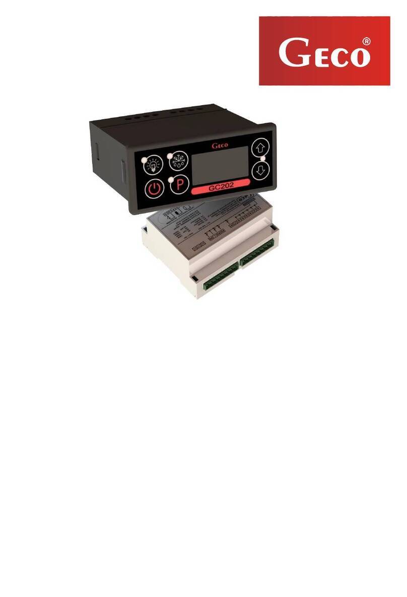
Geco G-204-P09 User manual

SERVICE MANUAL FOR THE CONTROLLER
G-204-P09
VERSION FOR REFRIGERATION EQUIPMENT
For programme version 02
We strongly request that you carefully study the instructions before connecting and
commissioning any of our devices.
If you have any problems with the operation and handling of your device, please
refer to the FAQ section on our website.
www.geco.pl.

Contents:
I. GENERAL CHARACTERISTICS.........................................................................................................3
II. DESIGNATION AND TECHNICAL DATA .....................................................................................3
III. METHOD OF ORDERING .................................................................................................................4
IV. DELIVERY, INSTALLATION AND CONNECTION.....................................................................4
V. PRINCIPLE OF ASSEMBLY OF SENSORS, TYPES OF PROTECTIVE SHELLS ..................4
VI. METHOD OF OPERATION...............................................................................................................5
VII. PROGRAMMING OF SYSTEM PARAMETERS............................................................................8
NOTES ON SBR PROGRAMMING. ............................................................................................................8
VIII. OPERATION OF THE G-204-P09 FOR THE USER .................................................................10
IX. PROBLEMS AND THEIR RESOLUTION .....................................................................................11
X. RETURNS FOR REPAIR..................................................................................................................11
XI. CONNECTION BLOCK DIAGRAM...............................................................................................12

page 3
I. GENERAL CHARACTERISTICS
The stand-alone Control Block, hereafter referred to as G-204, is a modern, convenient and
easy-to-use device. It was manufactured using microprocessor technology with automatic surface
mounting.
G-204 is designed to control condenser or evaporator fans. G-204 additionally includes an oil
temperature stabilising thermostat and a head overheat sensor.
Thanks to its one-piece housing, the controller can be mounted in a safe location. The
controller's operating parameters are only accessible to the service technician.
G-204 is equipped with three temperature sensors and the possibility of connecting a pressure
sensor. Four outputs allow direct connection of 230V devices with load capacity as per Table 1.
The controller displays the temperature or pressure on the condenser/evaporator and has an off
button.
These thermostats require no special maintenance; the keypad is made of a special type of foil
that is resistant to high temperatures and most chemicals. It must not be cleaned with sharp objects;
it is sufficient to wipe the front panel with a damp cloth from time to time.
II. DESIGNATION AND TECHNICAL DATA
Model designation: G- 2 04 –P 09 K 0 X –M XXX4 X0
Position: 1 2 3 4 5 6 7 8 9 10 11
1- "Geco" thermostat.
2- For refrigeration applications.
3- Housing type: 02 -mini panel, 03-large panel, 04-control in a module,
4- Beginning of panel (keyboard) markings.
5- Programme type 09.
6- Temperature setting method: К- keyboard.
7- Unused option
8- Buzzer: В- there is a buzzer, 0 - there is no buzzer.
9- Beginning of markings relating to the executive module.
10- Which relays are fitted.
Method of fan control: 0 - temperature, P - pressure.
Additional information on relay designation ...
Numbers indicate the presence of a relay, 0- no relay:
1 - relay,2 - relay, 3 - relay,4 - relay
Operating voltage - 230V +10% -15%
Ambient temperature - od +5°C do +40°C
Moisture - od 20% do 80% RH
Protection class - IP65 on the front side of the panel
Table 1: Relay designations and output load capacity
OUTPUT
TRIAK or
RELAY
RECOMMENDED MAXIMUM
CONTINUOUS LOAD
P1 –Fan
16A
3A
-
600W
P2 –Universal
16A
4A
1HP
750W

P3 –Universal
16A
4A
1HP
750W
P4 –Uniwersalny
16A
4A
1HP
750W
Attention !!!
- The currents shown in the table are the currents consumed by the individual
devices during normal operation and already take into account the inrush
currents of these devices !!!
- The total current drawn by the appliances at any one time must not exceed
10A !!!
III. METHOD OF ORDERING
The following types are available:
- With temperature control: G-204-P09K0B-M1234 00
- With pressure control: G-204-P09K0B-M1234 P0
Please additionally specify in your order:
- Length of temperature sensors.
IV. DELIVERY, INSTALLATION AND CONNECTION
1. The G-204 should be seated on the rail and locked with the latch..
2. Any metal parts through which the G-204 or its cables are passed should be filed or otherwise
secured. It is not permitted to secure the G-204 allowing water to act directly on it.
3. After mounting the G-204, connect the power cables according to the description on the wall.
Depending on the version of the G-204, some outputs may not be used - they will not be
described on the description sticker and zeros will be inserted in the type designation in the
appropriate places - no cables may be connected to these outputs !!!
4. The connectors used are approved for a continuous load of 16 A!!! They use fine thread and
special plates to prevent the wires from being cut, so even slight tightening results in
maximum good contact, while the use of greater force can lead to the thread breaking off.
This can result in melting of the socket and short-circuiting !!!
5. Any excess cable is shortened by cutting or coiling and bundled together using special plastic
ties. The cables must be securely fastened along their entire length and must not touch the
compressor and its accessories.
6. If heaters are used, their power must be selected so that if the G-204 or contactor fails and
they are switched on permanently, there is no possibility of fire or damage to the appliance.
V. PRINCIPLE OF ASSEMBLY OF SENSORS, TYPES OF PROTECTIVE
SHELLS
1. For each type of unit manufactured, the condenser sensor mounting location and SBR setting
must be selected experimentally. It is absolutely forbidden to change in any way the location or
method of fixing the sensors and the SBR setting without carrying out new tests on the
condenser cooling.
2. Sensor cables can be shortened or lengthened as desired, but the following rules apply:
-do not cut the sensor cable within 0.5 m. of the shell

page 5
-It is not recommended to extend the sensor cable beyond 20 m.
-THE WAY OF CONNECTING THE SENSOR CABLES TO THE TERMINALS OF THE
EXECUTIVE MODULE SENSORS IS ARBITRARY!!!
(analogous to the way of inserting a plug into a ~230V contact)
-for cable extensions we propose to use cable type OMY 2x0.5 mm
-The connection of the cables in the case of extensions should be made very carefully by
soldering each pair of wires and placing heat shrink sleeves over them. The connection point
should then be sealed with waterproof silicone and another heat shrink sleeve crimped over
it.
-the ends of wires connected to the S.B.R. shall be whitened with tin
VI. METHOD OF OPERATION
Thermostat functions:
Condenser cooling.
Temperature sensor.
The thermostat issues a fan proportional to the measured temperature within the range
parameter 'd0' - parameter 'd1'. If the temperature is higher than parameter 'd1' the blowing is
maximum. If the temperature is lower than parameter 'd0', the airflow is minimum (no
airflow).
Pressure sensor.
The thermostat issues a blower proportional to the measured pressure within the range
parameter 'd2' - parameter 'd3'. If the pressure is higher than parameter 'd3' then blowing is
maximum. If the pressure is lower than parameter 'd2', blowing is minimal (no blowing).
In the event of a failure of the control sensor, maximum airflow is activated.
Temperature
or pressure
Parameter
‘d0’or ‘d2’
Blow
Parameter
‘d1’or ‘d3’
Max

1. Evaporator blowdown
The thermostat works in the opposite way to the condenser, i.e. an increase in
pressure/temperature causes a decrease in blowdown.
2. Method of blowing
A maximum of 4 fans can be connected to the thermostat, a minimum of 1. The parameters
'r1', 'r2', 'r3' are used to determine which relay the fans are connected to. Fan P1 is speed-
regulated.
Airflow is realised by switching on the appropriate number of fans (P2, P3, P4) and
controlling the speed of fan P1.
If no relay has been selected to control the fans, all blowing is carried out by fan speed
control of fan P1.
Every 24 hours, the function of the relays selected to control the fans is switched over. This is
to even out the wear and tear on all fans. When the controller is switched off or the power is
switched on, the fan relays are ordered in the same way.
3. Oil heating
If one relay is selected to control the heater, the thermostat regulates the temperature set by
parameter 'd5' with hysteresis 'd6' based on the temperature measurement from the MISY
sensor.
In the event of failure of the SISY temperature sensor, the timer is controlled according to
parameters 'c8' and 'c9'.
Temperature
or pressure
Parameter
‘d0’or ‘d2’
Blow
czas
Parameter
‘d1’or ‘d3’
Max

page 7
4. Alarms
Compressor head overheating alarm
If parameter 'r5' is set to 1, the compressor head overtemperature alarm is allowed. The
parameter 'd7' sets the temperature above which the alarm will occur.
The alarm is signalled by the display 'A4'.
Temperature sensor failure alarms
A failure of sensor 3 (condenser) is signalled by the display 'A1'.
Failure of sensor 2 (sump) is signalled by the display 'A2'.
A failure of sensor 1 (head) is signalled by the display 'A3'.
If several alarms occur simultaneously, the cause of the alarm is displayed alternately.
The occurrence of any alarm causes the buzzer to beep and the alarm relay to be activated (if
selected by parameter).
5. Selection of relay functions.
Each relay can be configured for one of three functions. Whereby only one relay can be
selected to control a heater or alarm, while several can be selected to control a fan.
1- fan - more than one relay can be programmed with this option. The thermostat assigns
each fan a position in the cascade - the lower the relay number, the lower the
setting in the cascade. During operation, the function of the relays changes
sequentially.
2- Heater - this option activates the alarm from the failure of the bowl sensor, and activates
the heater control
3- Alarm - this option allows the relay to be used to switch on an alarm device such as a
siren.
6. The thermostat displays the temperature or pressure measured by sensor 3.
7. Relay activation is signalled by lighting up the appropriate diode, while triac activation is
signalled by a dot on the display.
8. Pressure sensor option:
The pressure value is not indirectly displayed. The value 0 is the minimum sensor
measurement value (4 mA) and the value 81 is the maximum measurement value (20 mA).
Depending on the type of sensor, this corresponds to different pressure values.

The measured pressure can be calculated from the formula:
VII. PROGRAMMING OF SYSTEM PARAMETERS
After commissioning and checking the correct operation of the device (the factory default settings
are entered), we proceed to enter the system parameters of the G-204.
To do that, turn off the device using the button . Then press the and
while holding them down press the button .Keep all three buttons pressed together for a
period of 3 seconds. Releasing any of the buttons during this time will exit the programming mode.
Once this is done, the LEDs on the buttons and should start to blink and and the display will
show 'c0' for one second. The last programmed value of this parameter will then appear. Now use
the key to enter the desired setting, each longer time the key is held down the display will
"scroll" rapidly. Then press , to accept the data entered and move on to entering the next
parameter.
It is possible to enter settings partially; if you do not want to change a given setting, press
and the G-204 will move on to the next parameter.
Attention !!!
The manufacturer of the refrigeration appliance can block
access to some or even all of the keypad parameters using
the computer programmer.
In this case, when an attempt is made to change the settings
of a blocked parameter, the display will show 'bL' for
approximately 1sec.
Notes on SBR programming.
1. IT IS THE RESPONSIBILITY OF THE MANUFACTURER OF THE COOLING
APPLIANCE AND THE SERVICE TECHNICIAN TO MAKE THE NEW SETTINGS
NECESSARY FOR THE NORMAL OPERATION OF THE APPLIANCE !!!
Programming should be carried out carefully, preferably by writing down the values of the
individual parameters on a piece of paper beforehand. It should be remembered that making any
mistake any error with certain parameters will have very serious consequences, including
including damage to the product and the refrigeration unit.

page 9
2. Once the unit has been programmed and put into operation, check the operation of the unit and
once again check that the system parameters have been set correctly.
3. It is absolutely forbidden to pass on to the end user the service manual or information on how to
program the SBR system parameters. The final user should only be provided with a copy of item
IX from this manual.
Table 2: Parameter designations
Para-
meter
Description
Min
Max
Krok
Default
setting
c0
minimum fan speed
5
32
1
5
c1
maximum fan speed
33
75
1
75
c8
Heater operating time when the control sensor fails
1
99
1min
20min
c9
Heater standstill time in case of control sensor failure
1
99
1min
20min
d0
Temperature at which there is minimum blowdown on
the condenser or maximum blowdown on the
evaporator
-40
98
1°C
1°C
d1
Temperature at which maximum blowing to the
condenser or minimum blowing to the evaporator
d0+1
99
1°C
60°C
d2
Pressure at which there is minimum blowdown on the
condenser or maximum blowdown on the evaporator
1
80
1
2
d3
Pressure at which maximum blowing to the condenser
or minimum blowing to the evaporator
d2+1
81
1
30
d5
Sump target temperature
1
50
1°C
10°C
d6
Oil sump heating hysteresis
0
10
1°C
2°C
d7
Head temperature above which the alarm
50
99
1°C
80°C
r1
P2 relay settings
0- not used
1- fan
2- heater
3- Alarm
00
03
1
01
r2
Settings for relay P3
as above
00
03
1
01

VIII. OPERATION OF THE G-204-P09 FOR THE USER
1. When the unit is plugged in, two dots will light up on the display for one second then the
unit's programme version and dots for another second. Two horizontal dashes will then light
up on the central segments of the display to indicate the "live" status. The device is started up
by pressing the button . The display shows the temperature value from the sensor on the
condenser.
2. If A1, A2 or A3 appears in the display, one or more sensors are faulty and service should be
contacted.
Doing repairs yourself will void the warranty and may lead to electric shock and
burns from hot vapours. Therefore, all repairs should be carried out by trained and
authorised service technicians !!!
r3
Settings for relay P4
as above
00
03
1
01
r5
Option - Is / is not an alarm from the compressor head
temperature sensor
1- alarm is present
0- no alarm
00
02
1
00
r6
Type of sensor controlling the fans
1- temperature sensor
2- pressure sensor
00
02
1
00
r7
Type of appliance to be controlled
1- Evaporator
2- Condenser
00
02
1
02
r8
Triac control when switching relays
0- stops the fan
1- Does not stop the fan
00
01
1
01

page 11
IX. PROBLEMS AND THEIR RESOLUTION
Signs of damage
Check
1.The display does not
light up despite the G-
204 being connected to
the mains
- presence of 220V at the L and N supply terminals
2. fan does not switch on
in spite of switch-on
indication
- red light
- presence of 220V at the W and N terminals - if present, check
the fan
5. Incorrect temperature
display
- connection of sensors to connectors
- correctness of sensor mounting
- condition of the sensor cable - the cable must not have any
damage
- exact appearance of the external surface of the sensor shell,
whether it has not been mechanically damaged.
7. Blinking dots on the
display, cannot be
switched on
- value of supply voltage
- condition of the supply connections
- tightening of supply connections
8. 'Abnormal', 'strange'
behaviour of the device.
- presence of 230V on supply terminals L and N
- condition of the supply terminals
- neutralisation of the refrigeration appliance
- condition of the electrical installation and the number of
appliances connected to one phase
- Control unit has not been exposed to water or other liquids
- that the controller is not exposed to humidity or sudden
temperature fluctuations
X. RETURNS FOR REPAIR
P.P.U.H. 'GECO' reserves the right to refuse to accept the appliance for
repair free of charge if the seals are found to be broken!!!
P.P.U.H. 'Geco' Sp. z o. o. shall not be liable for any loss or damage resulting
from the fact that the manufacturer of the cooling appliance or its service
provider has provided the final customer with information on how to make
changes to the system data of the SBR, incorrect or unprofessional installation,
or for losses resulting from the malfunction of the appliance.

XI. CONNECTION BLOCK DIAGRAM

page 13

page 15
Strona umyślnie
pozostawiona pusta
Table of contents
Other Geco Controllers manuals
Popular Controllers manuals by other brands

LINOVISION
LINOVISION IOT-C50 Series quick start guide

BKT Elektronik
BKT Elektronik EC335t Quick start manual

Mitsubishi Electric
Mitsubishi Electric MR-J5-G Series user manual

Horizont
Horizont trapper B22 instruction manual

Mitsubishi Electric
Mitsubishi Electric FX5-DP-M user manual

heat-timer
heat-timer TR1000 Installation and operation manual

Emerson
Emerson IC200CX EVO user manual

Mitsubishi Electric
Mitsubishi Electric MELSEC iQ-R Series user manual

Festo
Festo CMMS-AS G2 Series Assembly and installation

TJERNLUND
TJERNLUND MAC-4 CONTROL (DISCONTINUED) 8504088 REV A... manual

gefran
gefran 800P Installation and operation manual

Advantech
Advantech ADAM-5630 Series user manual