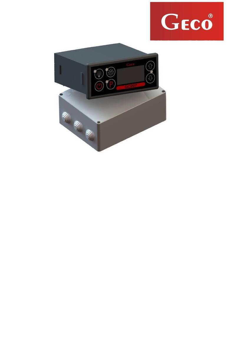
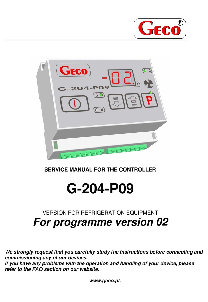
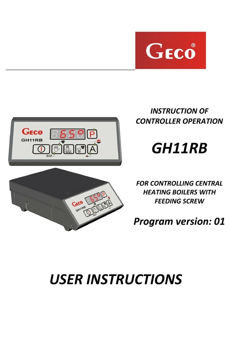
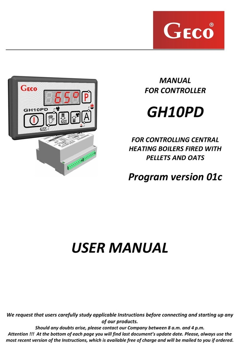
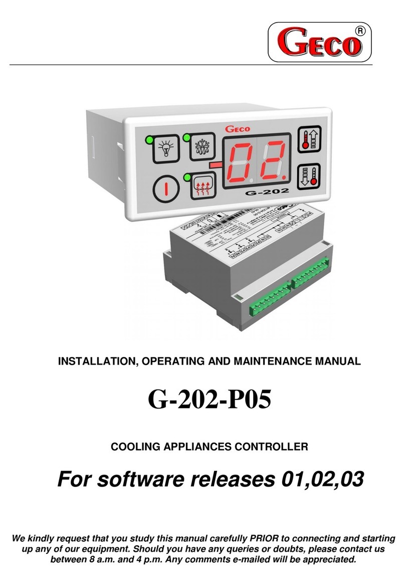
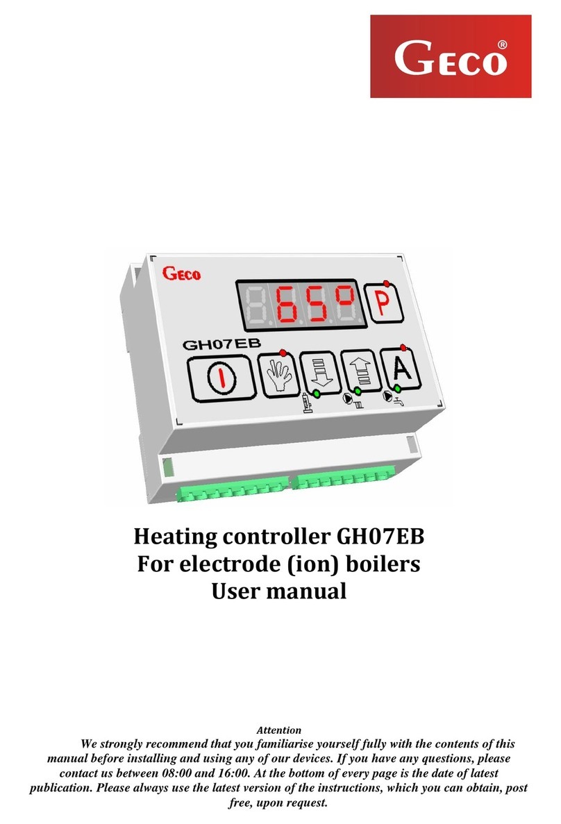
Geco G-204-P00K Series User manual

P.P.U.H. “Geco” spółka z o. o. [Ltd.]
30-134 Krakow, No. 112A Zarzecze Street
tel. +48 (12) 6369811,6361290
fax. +48 (12) 6362002
e-mail: [email protected]
http://www.geco.pl
SERVICE MANUAL
FOR AN INDEPENDENT
CONTROL BLOCK [ICB]
G-204-P00K…
OPTION FOR REFRIGERATING EQUIPMENT
For Program Version 01
Please, read this manual thoroughly before connecting and activating any piece of equipment
from Geco. In case if you have any doubts, please contact our company between 8 a.m. and
4 p.m. All comments sent by e-mail will provide valuable aid for us.
Attention !!! At the bottom of the following pages you will find the date of last update,
and the end of page 16 shows information on successive changes of program version
and the way it operates.
Please, always use the most recent issue of the manual, which is available from us free of
charge by mail after ordering.

page 2 SERVICE MANUAL FOR MANUFACTURERS ICB TYPE G-204-P00K
PPUH “GECO” - G-204-P00K program version 01 PRINTOUT DATE 05-03-09
I. GENERAL CHARACTERISTICS
Independent Control Block, later referred to as the G-204, is a modern device, which is comfortable
and easy to use. It has been manufactured using microprocessor technology, and automatic surface
mounting.
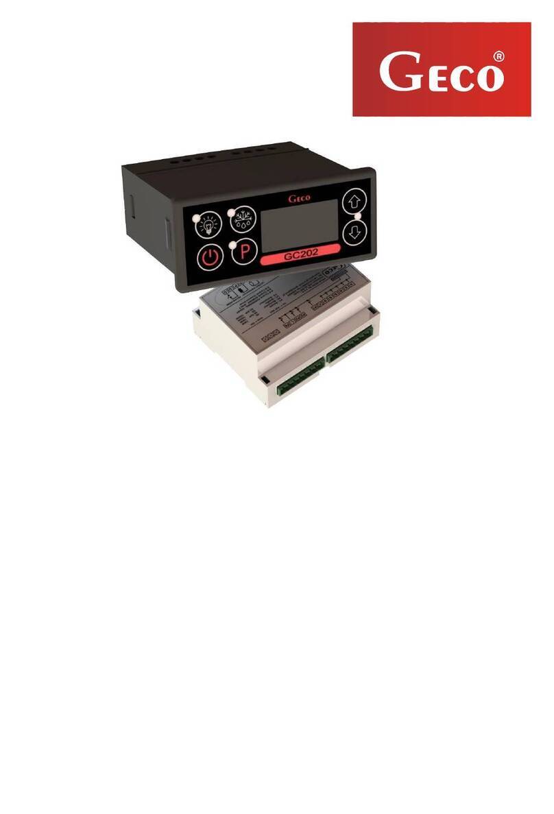
G-204 is a single-module version of the G-203-P00K thermostat, fitted on a rail.
G-204 has been equipped with two temperature probes - it is possible to connect the door probe to
the control panel or executing module - then they work at safe 5V voltage, and four outputs allowing to
connect directly equipment working at 230V, with loading potential as shown in Table 1.
In case if it is used in refrigerating equipment, the G-204 stabilises temperature and controls automatic
defrosting, and this function length may be adapted to specific surrounding conditions, and it also has a
push-button for manual boiler de-icing. Moreover, the G-204 may be provided extra with lighting
switch working independently of main switch.
These thermostats do not require any special maintenance; keyboard has been made of special foil type
resistant to high temperature and most chemical agents. It is unacceptable to clean it with sharp-ended
objects, it is sufficient to wipe the front panel occasionally with wet cloth, only after having
disconnected the unit.
II. SYMBOLS AND TECHNICAL DATA
Model designation: G- 2 04 –P 00K X X – M XXXX X
Item: 1 2 3 4 5 6 7 8 9 10 11
1- “Geco” thermostat.
2- For use in refrigerating engineering.
3- Casing type: 02 – mini-panel, 03 – large keyboard (also with potentiometer), 04 – single-
module to be fixed on rail.
4- First symbol describing panel (keyboard).
5- Program version (00 – general-purpose).
6- Temperature presetting method: (Р- potentiometer, К- keyboard).
7- Light push-button: L – light push-button installed, 0 – no light push-button.
8- Buzzer: В– buzzer installed, 0 – no buzzer.
9- First symbol describing the executive module.
10- Shows which relays are installed. Detailed specification is provided below.
11- Door probe: D – mechanical or magnetic door probe, Y – optical door probe, 0 – no option
to connect any door probe.
Additional information regarding relay symbols.
Digits indicate that relay is installed, 0- no relay:
1 – compressor relay - must be provided
2 – light relay
3 – fan relay
4 – heater / valve relay.
The simplest thermostats contain:
•1000 - compressor
•1200 - compressor and light
and most developed ones:
•1034 - compressor, fan, heater
•1234 - compressor, light,fan, heater
Other examples:

page 3
•1030 - compressor and fan
•1004 – compressor and heater
•1230 – compressor, light,fan
•1204 – compressor, light,heater
Working voltage - 230V +10% -15%
Ambient temperature - from +5°C to +40°C
Humidity - from 20% to 80% RH
Protection degree - IP65 from control panel front side
Table 1: Relay symbols and output current-carrying capacity
Output Carrying capacity
P1 – Compressor 8A 2HP 1500W
P2 – Light 4A - 750W
P3 – Fan 4A 1HP 750W
P4 – Heater / Valve 8A - 1500W
Attention !!!
•Currents shown in the table are taken by individual devices during
regular operation and they already include starting currents of
these devices !!!
•Total current taken at the same time by all equipment shall not exceed 10A !!!
III. HOW TO ORDER
When ordering, provide the following:
1. Controller type: e.g. G204-P00KLB-M1234 D.
2. Length of temperature probes.
3. It is also possible to make an extra order for door probes working in a fully contactless way:
•magnetic probe, operating range 1-2 cm;
•optical probe, operating range 1-2 cm.

page 4 SERVICE MANUAL FOR MANUFACTURERS ICB TYPE G-204-P00K
PPUH “GECO” - G-204-P00K program version 01 PRINTOUT DATE 05-03-09
IV. DELIVERY, ASSEMBLY AND CONNECTION
1. Fix the G-204 unit on rail and lock it with a latch.
2. All metal elements, through which the G-204 or its cables are put, shall be filed off or protected
in other way. It is unacceptable to mount the G-204 in a way allowing water to contact it
directly (e.g. water condensing on lower display case housing), to touch discharge tube from
evaporator, etc., and generating considerable changes of its temperature in relation to ambient
temperature (e.g. installing the unit in direct vicinity of the compressor and its accessories, and
cooled and heated elements).
3. As soon as the G-204 unit is fixed, connect power cables according to the specification provided
on its side walls. Depending on the G-204 version, certain outputs may remain unused - they
will not be described on the specification label, and proper items in the type designation will
contain zeros - it is prohibited to connect any cables to these outputs !!!
4. All connectors used are certified for continuous load 16A!!! They have fine thread and special
plates preventing cables from being cut, and that is why even light tightening ensures very good
contact, and use of any greater force may result in thread break. This may result in socket being
melted and shorting !!!
5. Shorten all cable allowances by cutting them or winding up and putting together with special
plastic bands. The cables have to be well-fixed along their entire length and they may not touch
either the compressor or its accessories.
6. When the unit is connected to power supply, voltage may occur in the lighting cable, no matter
if the unit is turned on or off with the push-button, and that’s why it is allowed to
replace starter or fluorescent lamp only when power supply cable is unplugged !!!
THE SAME PROVISION APPLIES TO EXECUTION
OF ANY OTHER REPAIRS !!!
8. If heaters are used, select their power so as to ensure that in case if the G-204 or contactor breaks
down and heaters are permanently on, there is no chance for fire or unit damage. If high-power
heaters are used, absolutely use safety thermostat on evaporator - the thermostat should be of
a different type, e.g. mechanical.

page 5
V. PROBE FITTING GUIDELINES, PROTECTIVE SHELL TYPES
1. For each type of manufactured unit it is required to select experimentally locations for room probe
and evaporator probe, and ICB (Independent Control Block) settings. It is strictly prohibited to
alter in any way probe mounting location or method, and the ICB settings, without carrying out new
tests on temperature stabilisation and the device defrosting process !!!
2. Fit the room probe so as to prevent it from touching food products, and to protect it from damage
while cleaning the device. Use special plastic grip to fix this probe. This solution will induce rapid
(time delays on/off - see section VI par. 6 and 7) reaction of probe and the whole thermostat to the
change of air temperature in the device. If this is recommended or necessary to slow down and
“smooth” probe reaction time to temperature changes, we propose to fix it to any metal element of
the unit.
3. Fix evaporator probe so as to ensure best possible contact with the evaporator lamella, in a location,
where ice stays longest during defrosting. It should be fixed so as to prevent it from being pushed
out by building up ice. If possible, the probes should be fixed vertically to ensure that the cable
comes out from probe bottom.
4. It is possible to shorten or lengthen probe cables freely, however provided that the rules listed
below are observed:
-do not cut off probe cable at a distance shorter than 0.5 m from shell;
-we do not recommend to lengthen probe cable more than 20 m;
-METHOD USED TO CONNECT PROBE CABLES TO THE TERMINALS AT EXECUTIVE
MODULE PROBES IS FREE TO CHOOSE !!!
(the same as method to plug in the cable – to ~230V);
-we recommend using cable type OMY 2x0.5 mm to lengthen cables;
-be particularly careful when connecting cables in case of their lengthening, solder each
conductor pair and put on them heat-shrinkable sleeves. Then pour water-resistant silicone on
cable joint and put on it one more heat-shrinkable sleeve;
-cable ends connected to the ICB shall be coated with tin.

page 6 SERVICE MANUAL FOR MANUFACTURERS ICB TYPE G-204-P00K
PPUH “GECO” - G-204-P00K program version 01 PRINTOUT DATE 05-03-09
VI. PRINCIPLE OF OPERATION
A - General Information
1. As soon as the device is plugged in, a 3-second long start procedure will be executed. During that
procedure, the display will show two dots for one second, the controller program version for the next
second, and then two dots again. During that period no controlled device will be turned on.
2. As soon as the start procedure is complete, two horizontal dashes will light from point 1 on central
display segments. The dashes signal “live” condition – if the unit has not been previously on !!!.
Press push-button to activate the device. The display will show temperature value from the
room probe.
3. After pressing and holding push-button for 0.5 second, the display will start to blink and show
the evaporator temperature, and after another 5 seconds the G-204 will automatically return to the
room temperature readout. Attention!!! This function works also during defrosting, when the
display shows “dF”. It is also possible to see temperature from room probe by pressing for 0.5
second, the display will start to show room temperature (no blinking), and after another 5 seconds
the G-204 will automatically return to displaying “dF”.
4. Lighting small red diode (dot) in right bottom corner of the temperature display indicates
compressor activated. This allows for easier check of possible system defects.
5. If the compressor should be activated, and this does not happen because of activation of any
safeguards (see par. 6, 7, 10 and 11), the dot signalling compressor operation will keep blinking. As
soon as preset time from safeguards passes, the dot will start to light permanently and the
compressor will be activated.
6. Delay in compressor activation after reaching its activation temperature (temperature preset by user
minus lower hysteresis value) is 30 seconds. If the temperature drops during that period, the
condition of exceeded 30 seconds will be rechecked. This is expected to protect the compressor
from unnecessary activation due to e.g. putting products in, draughts, etc.
7. Each time after preset temperature is reached (temperature preset by user plus upper hysteresis
value), and after each power failure or voltage drop below 175V, the G-204 will make it impossible
to reactivate the compressor for time period specified by parameter ‘c2’. However, if ‘c2’=0min,
after current decay the safeguard will last for 60 seconds.
8. When the device is activated with push-button , there will be a 5-second delay in compressor
activation. However, user must remember that this cancels the power failure safeguard from par. 7 -
this also applies to time specified by parameter ‘c2’ after having switched the compressor off. This
allows for faster compressor operation check.
9. The controller has been equipped with alarms indicating probe damage. The controller will react in
different ways, depending on which probe has been damaged.
•Room temperature probe damage will result in symbol A1 being displayed. The controller will
turn on the compressor in time cycle (so-called clock control), according to time values specified
in parameters ‘c8’ and ‘c9’. Defrosting will function normally.
•Evaporator probe damage will result in alarm A2 being displayed. Manual and automatic
defrosting function will be blocked !!! The only method allowing to defrost the device is to
turn it off using push-button and to wait until ice melts naturally.
•In case if two probes fail simultaneously, only alarm A1 will be displayed. As soon as room
probe is repaired, alarm A2 will light.

page 7
10. If a buzzer is installed in the controller – see section II, the controller will signal pressing of any
push-button with buzzer beep. When the controller is off (two horizontal dashes on the display),
the buzzer will signal only push-buttons and being pressed.
11. Lighting is switched on and off by pressing push-button . Green diode at the button lights in
order to signal this. If light is on due to door opening, the diode will not switch on.
Push-button works independently of thermostat power switch - .
B - Defrosting
1. If extra defrosting is needed due to severe operating conditions, press push-button . As a result,
green diode in push-button will light continuously, and the display will show “dF” instead of
measured temperature value, then the unit will enter the defrosting cycle.
2. If defrosting takes place and evaporator temperature is higher than the value set in parameter ‘d2’,
then after approximately 10 seconds the unit will enter the defrosting exit phase, and as soon as it is
closed, it will continue operation.
3. If defrosting takes place and evaporator temperature is lower than the value set in parameter ‘d2’,
then the G-204 will activate defrosting, and as soon as temperature from parameter ‘d2’ is reached, it
will enter the defrosting exit procedure (this status is indicated by blinking of green diode in push-
button ), while in option with heaters the defrosting exit procedure will take place that consists of
two successive phases:
•dripping phase – in which the compressor and evaporator fans remain off for time period
specified in parameter ‘c3’;
•evaporator freezing out phase – in which only the compressor works in order to reduce
evaporator temperature to the value specified in parameter ‘d5’, prior to fans restart. Parameter
‘c4’ determines maximum and impassable freezing out time independently of reaching
temperature ‘d5’ by evaporator.
4. Defrosting exit procedure will be ended with activation of fans, switching off “dF” on the display
and switching off green diode blinking in push-button .
5. In case if there are no fans, or they are not connected to the ICB, the system will behave as if they
were installed.
6. Defrosting will end as soon as evaporator reaches temperature value preset in parameter ‘d2’, or
after time preset in parameter ‘c1’ has passed.
7. When “dF” is switched off and defrosting is complete, the display will show temperature saved in
memory just before defrosting start for time specified in parameter ‘c7’ – this is expected to prevent
from complaints due to abrupt temperature changes in the device.
8. The system will behave in the same way at manual and automatic defrosting.
C – Door probe principle of operation
1. If door is opened, the fan will be immediately stopped and light may be switched on in the G-204,
depending on parameter ‘r7’ setting. The display shows temperature.
2. If door has not been closed, after 30 seconds the display will show permanently symbol “dr”.
Short sound signal is generated in controllers with installed buzzer, and repeated every 30 seconds.
3. If door still has not been closed after time period specified in parameter ‘r8’, alarm will be
activated, which is signalled by blinking display showing symbol “dr”, and in controller option
equipped with buzzer - sound signal. At this moment the compressor will be switched off.
4. In case if R8 = 0, alarm will be activated immediately after door opening.

page 8 SERVICE MANUAL FOR MANUFACTURERS ICB TYPE G-204-P00K
PPUH “GECO” - G-204-P00K program version 01 PRINTOUT DATE 05-03-09
5. It is possible to mute the alarm by pressing any push-button. When door is closed, alarm will be
deactivated and further operation resumed.
6. The controller allows to connect both mechanical open door probe, which closes while door is open
(R6=01), and mechanical or magnetic probe, which opens while door is open (R6=02).
HYSTERESIS
While programming parameters ‘d0’ and ‘d1’ (minimum and maximum temperature, which may be set
by customer), remember that hysteresis value ‘d3’ causes additional temperature shift down and up from
temperature value preset by user.
This is particularly important in case of so-called ‘plus’ devices, which should always work at
temperature values above 0ºC.
As the refrigerating system Manufacturer, in this case refrigerated counter (temperature values above
0ºC) we require the unit to permit operation in temperature range within values provided below: OFF
min: 2ºC. ON max: 10ºC.
Symmetrical hysteresis for even
‘d3’ values
Symmetrical hysteresis for odd
‘d3’ values
Example 1.
For example, let’s set hysteresis ‘d3’ to 2ºC
In order to set hysteresis as before, we should
set parameters ‘d0’ at 3ºC and ‘d1’ to 9ºC
Example 3.
For example, let’s set hysteresis ‘d3’ to 3ºC
In order to set hysteresis as before, we should
set parameters ‘d0’ at 3ºC and ‘d1’ to 8ºC
Example 2.
For example, let’s set hysteresis ‘d3’ to 4ºC
In order to set hysteresis as before, we should
set parameters ‘d0’ at 4ºC and ‘d1’ to 8ºC
Example 4.
For example, let’s set hysteresis ‘d3’ to 5ºC
In order to set hysteresis as before, we should
set parameters ‘d0’ at 4ºC and ‘d1’ to 7ºC
ON temperature
Temperature
preset by user
‘
d3
’
OFF temperature
‘
d3
½
‘d3’+0.5ºC
½
‘
d3
’-
½
‘
d3
’
½
‘d3’

page 9
VII. ACTIVATION DIAGRAMS FOR INDIVIDUAL DEVICE SUBASSEMBLIES
Wide line indicates activation (ON), and intermittent line - deactivation (OFF) of individual devices.
Defrosting exit consists of two phases - see section Vpar. 3.
Field “Stop” indicates deactivation, and “Operation” - activation of compressor due to exceeded
programmed temperature value, certainly taking into account programmed hysteresis value - parameter
‘d3’.Heater on Fig. 1 is designed to heat up tray and/or water discharge hose from evaporator. Heater
from diagram 4. is designed only to heat up water discharge hose from evaporator.
ERROR IN PARAMETER SETTINGS WILL RESULT IN ERRATIC UNIT OPERATION !!!
1. Defrosting by compressor stop ‘r1’=01, fans work only together with compressor ‘r2’=00
t=0 (c3 i c4 bez znaczenia)
K O M P RE SO R
GRZAŁKA TACKI
WENTYLATOR
Postój Praca ROZM RAŻANIE WYJŚCIE Z ROZMRAŻANIA Praca Postój
2. Defrosting with heater ‘r1’=02, fans work only together with compressor ‘r2’=00
t=c3 t=c4
K O M P RE SO R
G R Z A ŁKA
WENTYLATOR
Postój Praca ROZM RAŻANIE WYJŚCIE Z ROZMRAŻANIA Praca Postój
3. Defrosting with hot vapours ‘r1’=03, fans work only together with compressor ‘r2’=00
t=c3 t=c4
K O M P RE SO R
ZA W Ó R
WENTYLATOR
Postój Praca ROZM RAŻANIE WYJŚCIE Z ROZMRAŻANIA Praca Postój
4. Defrosting with hot vapours ‘r1’=03, fans work all time after unit activation ‘r2’=01
t= c3 t=c4
K O M P RE SO R
ZA W Ó R
WENTYLATOR
Postój Praca ROZM RAŻANIE WYJŚCIE Z ROZMRAŻANIA Praca Postój
5. Defrosting by compressor stop ‘r1’=01, fans work all time after unit activation ‘r2’=01
t=0 (c3 i c4 bez znaczenia)
K O M P RE SO R
G R Z A ŁKA ODPŁ.
WENTYLATOR
Postój Praca ROZM RAŻANIE WYJŚCIE Z ROZMRAŻANIA Praca Postój
6. Defrosting with heater ‘r1’=02, fans work all time after unit activation ‘r2’=01
t= c3 t=c4
K O M P RE SO R
G R Z A ŁKA
WENTYLATOR
Postój Praca ROZM RAŻANIE WYJŚCIE Z ROZMRAŻANIA Praca Postój
ª
COMPRESSOR
TRAY HEATER
FAN
COMPRESSOR
HEATER
FAN
COMPRESSOR
VALVE
FAN
COMPRESSOR
VALVE
FAN
COMPRESSOR
DISCHARGE HEATER
FAN
COMPRESSOR
HEATER
FAN
Sto
p
O
p
eration DEFROSTING DEFROSTING EXIT O
p
eration Sto
p
Stop Operation DEFROSTING DEFROSTING EXIT Operation Stop

page 10 SERVICE MANUAL FOR MANUFACTURERS ICB TYPE G-204-P00K
PPUH “GECO” - G-204-P00K program version 01 PRINTOUT DATE 05-03-09
VIII. SYSTEM PARAMETERS - PROGRAMMING
As soon as you activate and check correct unit operation (standard settings are entered in factory), start
entering the G-204 system parameters.
In order to do that deactivate the unit with push-button . Then press push-buttons and ,
and, holding them down, press push-button . Keep all three push-buttons pressed together for 3
seconds. If any push-button is released too early, the unit will exit programming mode. When this
operation is completed, the diodes in push-buttons and should begin to blink, and the display
will show symbol ‘c0’ for one second. Then the last programmed value of this parameter will appear.
Next, using push-buttons , enter required settings, each time a push-button is pressed and held,
displayed values will be scrolled at fast rate. Then, press to accept entered data, and go to next
parameter entering mode.
Partial entering of settings is possible; if you do not want to modify particular setting, press and the
G-204 will switch to next parameter.
Attention !!!
Using computer programmer, refrigerating system Manufacturer may block access to
some or even all parameters from keyboard. In that case if there is any attempt to
modify settings of blocked parameter, the display will show symbol ‘bL’ for
approximately 1 second.
Comments regarding the ICB programming.
1. REFRIGERATING SYSTEM MANUFACTURER AND SERVICE CENTRE ARE OBLIGED
TO ENTER NEW SETTINGS NECESSARY FOR NORMAL DEVICE OPERATION !!!
2. Carry out programming carefully - it is best to start with writing down values of individual
parameters on a sheet of paper. Remember that in case of some parameters making of any error will
have very serious consequences, including product and refrigerating system damage.
3. As soon as unit is programmed and activated, check the way it works and once more verify correct
system parameters settings.
4. It is strictly prohibited to pass to final user either the service manual or the information how to
program the ICB system parameters. Final user shall be provided only with a copy of section IX in
this manual.

page 11
Table 2: Parameter definitions
Para-
meter
Description Min. Max. Step Factory
setting
c0 Time interval between defrosting Attention!!! In case if this
parameter is set to “0” there will be no automatic defrosting, but
only manual one!!! If this parameter is set to “-01” there will be
neither automatic nor manual defrosting!!!
0
-01
24 1h 6h
c1 Maximum defrosting time if evaporator does not reach preset
temperature (parameter d2) Attention!!! In case if this parameter
is set to “-01”, there will be no time limit.
10
-01
99 1min 30min
c2 Minimum compressor stoppage time. 0 15 1min 3min
c3 Evaporator dripping time. 0 15 1min 2min
c4 Evaporator freezing out time, after which fans will be activated
independently of whether evaporator has reached temperature value
preset in parameter ‘d5’.
0 25 1min 10min
c5 Maximum compressor operation time
0 – indicates no test (deactivation of this parameter).
0 99 1min 40min
c6 Compressor stoppage time after activation of safeguard from
parameter ‘c5’.
0 99 1min 10min
c7 Time period after defrosting end (parameter ‘c4’), for which
measured temperature will be shown before defrosting starts.
0 60 1min 5min
c8 Compressor operation time in case of control probe damage. 1 99 1min 25min
c9 Compressor stoppage time in case of control probe damage. 1 60 1min 5min
d0 Minimum temperature to be set by customer. -40 20 1°C 1°C
d1 Maximum temperature to be set by customer. d0+1 40 1°C 10°C
d2 Evaporator temperature, at which defrosting ends. 0 40 1°C 5°C
d3 Hysteresis value. 1 10 1°C 2°C
d4 Graduation value for room probe in relation to actually measured
temperature.
-10 10 1°C 0°C
d5 Evaporator temperature, at which fans will start operation after
defrosting process end.
-30 10 1°C -5°C

page 12 SERVICE MANUAL FOR MANUFACTURERS ICB TYPE G-204-P00K
PPUH “GECO” - G-204-P00K program version 01 PRINTOUT DATE 05-03-09
r1 Specifies evaporator defrosting method, parameter set to:
01 – defrosting by compressor stop
02 – defrosting with heater
03 – defrosting with hot vapours - valve (reverse cycle)
01 03 1 02
r2 Specifies evaporator fans operation method, parameter set to:
00 – fans operate only with compressor
01 – fans operate all time after switching on power
A
TTENTION!!! This parameter has no effect on evaporator
defrosting cycle and method.
00 01 1 01
r3 Specifies temperature control method, parameter set to:
00 – regular control
01 – temperature is controlled according to measurements from
evaporator probe, programmed temperature and parameters D0, D1,
D2 and D3 relate to evaporator probe, measurements from room
probe is being displayed.
00 01 1 00
r5 Conditions for defrosting activation during the unit start.
00 – operation start without defrosting
01 – if there was power failure during defrosting, then defrosting
would be activated
02 – defrosting each time when the device is plugged in.
00 02 1 00
r6 Door probe option
00 – no door probe
01 – there is door probe closed at open door
02 – there is door probe open at open door
00 02 1 01
r7 Lighting activation method
01 – light control only by door probe
02 – light control only by key
03 – light control by door probe and key
01 03 1 03
r8 Time from door opening moment to alarm activation.
Symbol “dr” will be displayed 30 seconds after door opening. Short
sound signal is generated in controllers with installed buzzer, which
is repeated every 30 seconds.
When time R8 passes, an alarm will be activated, which is signalled
by symbol “dr” blinking on the display, and in controller version
with buzzer - by a sound signal, and the compressor will be switched
off.
0 – indicates immediate alarm activation.
0 20 1min 1min
r9 Place to connect the door probe:
01 – probe connected to the module with relays
00 – probe connected to the control module – Attention, order
special cable with plug in this case !!!
00 01 1 01

page 13
IX. THE G-204 OPERATING FOR USER
1. After plugging in the device, the display will show two dots for one second, then its program
version, and two dots for another second. Then, two horizontal dashes indicating “live” condition
will light in central segments of the display. The unit will be activated after pressing push-button
. The display will show temperature value from room sensor.
2. Setting of temperature stabilised in the display case.
•Press push-button in order to modify settings. Green diode in the push-button will light
then, and the display will show the last programmed temperature value.
•Push-buttons are used to preset temperature. Each time you press and hold any of these
push-buttons, the indications will be scrolled at fast rate.
•When required temperature is set, press push-button again. When this is done, the green
diode in the push-button will go off, and the G-204 will exit the programming mode and it will
start to execute a new program.
•If push-button is not pressed, the G-204 will automatically exit the programming mode
after approximately 5 seconds after push-buttons are used last. In this case temperature value
will not be saved.
3. You will switch lighting on and off by pressing push-button , lighting is activated when the
green diode is on. Light switch works independently of master switch .
ATTENTION - IMPORTANT !!!
If extra defrosting is needed due to severe operating conditions, press push-button . As a result,
green diode in push-button will light, and the display will show “dF” instead of measured
temperature value, and the unit will enter the defrosting cycle.
Defrosting will be finished automatically when preset time passes, or when temperature value
programmed by refrigerating system Manufacturer is reached.
Repairs carried out on user’s own will result in warranty loss, and they may lead to electric
shock and hot vapour burns. Therefore, all repairs should be performed by well-trained and
licensed servicemen !!!

page 14 SERVICE MANUAL FOR MANUFACTURERS ICB TYPE G-204-P00K
PPUH “GECO” - G-204-P00K program version 01 PRINTOUT DATE 05-03-09
X. TROUBLESHOOTING
Failure symptoms Items to check
1. The display is off
although the G-204 is
plugged in.
Check:
- if there is 220V voltage on power terminals L and N
2. The compressor is
off although signalling
indicates that it is on
-red diode
Check:
- if there is 220V voltage on power terminals K and N – If voltage is
correct, check the compressor
3. Defrosting heater
cannot turn on Check:
- if there is 220V voltage on power terminals according to
specification on upper wall of the executive module
- if voltage is correct, check the heater
4. Fluorescent lamp
does not light
Check:
- if there is 230V voltage on power terminals according to
specification on upper wall of the executive module
- if voltage is correct, check the following: a/ starter b/ fluorescent
lamp c/ choke
5. Erratic temperature
indication Check:
- probe connection to connectors
- value of parameter ‘d4’
- correct probe fitting
- probe cable condition – the cable cannot be damaged in any way
- carefully inspect appearance of probe shell external surface,
whether it has not been mechanically damaged.
6. It is impossible to
preset required
temperature value
Check:
- values of parameters ‘d0’ and ‘d1’ (d0<d1)
7. Blinking terminal
dots, no possibility to
make it work
Check:
- supply voltage value
- condition of power connectors
- whether power connectors are tight
8. Abnormal, odd unit
behaviour. Check:
- if there is 230V voltage on power terminals L and N
- condition of power connectors
- refrigerating system zeroing
- wiring system condition and number of devices connected to
single phase
- if you have suitable thermostat type (label with specification of
outputs) for your refrigerating system
- if the G-204 has not been exposed to water or any other liquid
- if the G-204 is not exposed to humidity or abrupt temperature
changes

page 15
9. Problems with unit
defrosting Check:
- values of parameters ‘d2’ and ‘c0’, ‘c1’
- value of parameter ‘c1’. This is maximum device defrosting time,
independently of the fact whether evaporator has reached
programmed defrosting end temperature or not (parameter ‘d2’). If this
time period is too short, the device will not be fully defrosted.
- correct probe fixing to evaporator lamella
PROBE MUST BE WELL-FIXED AND CLOSELY ADHERE TO
LAMELLA !!!
- whether evaporator probe is mounted in a location, where ice stays
longest, otherwise check temperature on the probe at the moment,
when last pieces of ice fall from evaporator. THEN, THIS
TEMPERATURE SHOULD BE ENTERED AS PARAMETER ‘d2’
10. The unit does not
reach preset
temperature and does
not work
Check:
- temperature programmed by user
- values of individual parameters, and in particular ‘c2’, ‘c5’, ‘d0’, ‘d1’
- par. 9 - Problems with the unit defrosting. If the unit is not fully
defrosted, it will not reach programmed temperature !!!
- room probe fitting method and location
- whether cabinet side glass panels or display case sliding glass panels
have not been removed
- IF THE UNIT IS NOT EXPOSED TO DRAUGHT OR DIRECT
SUNLIGHT !!!
- whether there aren’t any fans or air conditioners fixed on ceiling or
nearby
- condenser cleanness
- temperature in store (each manufacturer specifies max. unit operating
temperature)
- volume of gas, fans, evaporator heater, hose discharging water from
evaporator
11. incorrect door
probe operation Check:
- values of parameters ‘r6’ and ‘r7’, ‘r9’
- correct probe connection

page 16 SERVICE MANUAL FOR MANUFACTURERS ICB TYPE G-204-P00K
PPUH “GECO” - G-204-P00K program version 01 PRINTOUT DATE 05-03-09
XI. RETURNS FOR REPAIR
In case if there is an ICB failure and the unit must be returned for repair, it is strictly
required to fill in completely the replacement form provided at the end of this
manual. We suggest not to remove the form, but only to make its photo copy.
PPUH ‘GECO’ reserves the right to refuse acceptance of any unit for
free of charge repair in case if there is no form enclosed with it, or
the form is incomplete, and in case if any seal break is found !!!
P.P.U.H. ‘Geco’ Sp. z o. o. [Ltd.] shall bear no responsibility for losses and
damage in case if the refrigerating system Manufacturer or his service centre
provides final customer with access to information on how to enter
modifications in the ICB system data, in case of wrong or unprofessional
installation, or for losses incurred due to erratic unit operation.

page 17
XII. THE G204 - BLOCK DIAGRAM AND OVERALL DIMENSIONS WITH
LIGHT PUSH-BUTTON INSTALLED AND WITHOUT IT
106 mm
90 mm
106 mm
90 mm

page 18 SERVICE MANUAL FOR MANUFACTURERS ICB TYPE G-204-P00K
PPUH “GECO” - G-204-P00K program version 01 PRINTOUT DATE 05-03-09
V
PANEL
Failure: ACTUATOR.
SERVICE CENTRE STAMP
THE ICB REPLACEMENT FORM
DETAILED ICB DEFECT DESCRIPTION:
Table of contents
Other Geco Controllers manuals
Popular Controllers manuals by other brands

Deif
Deif CGC 400 Reference book

EFI
EFI E-85A Installation and service guide

Motorola
Motorola iDEN Site Controller System manual

Philips
Philips 9890 000 0268 Series Service manual

Advanced Electronic Applications
Advanced Electronic Applications PK-88 operating manual

gefran
gefran 450-R-R-1 Installation and operation manual