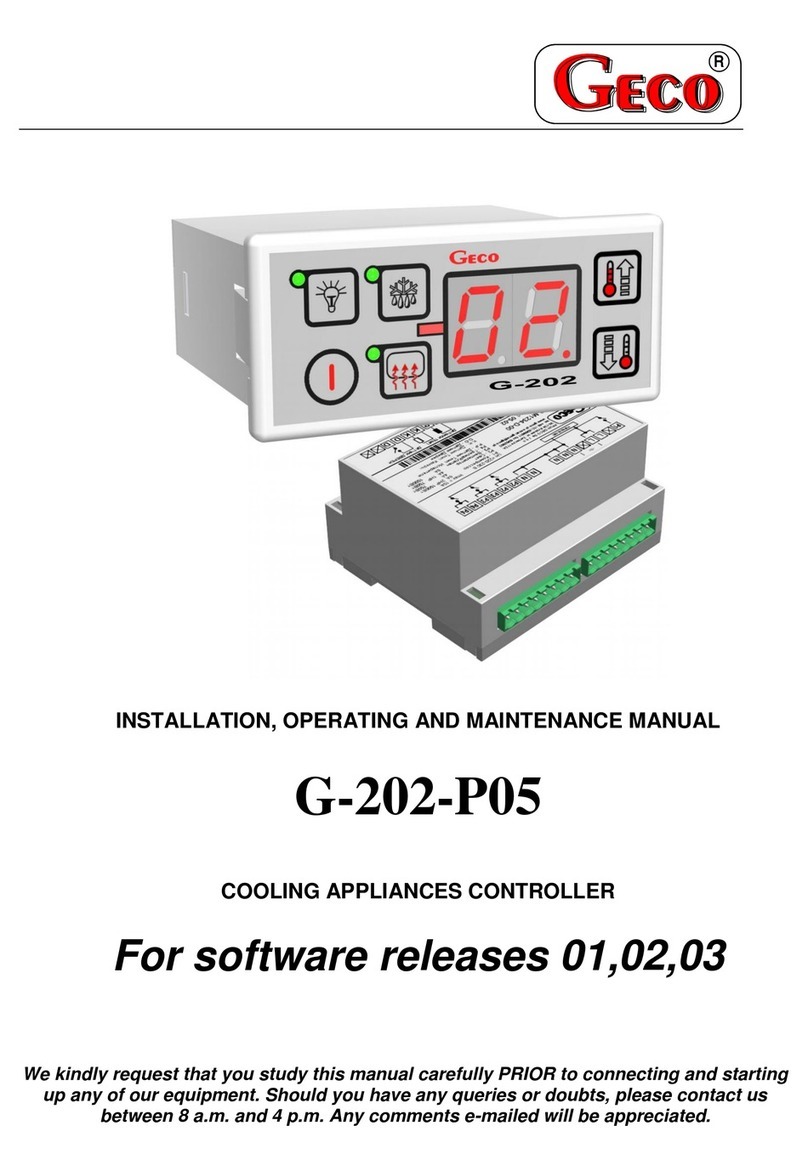
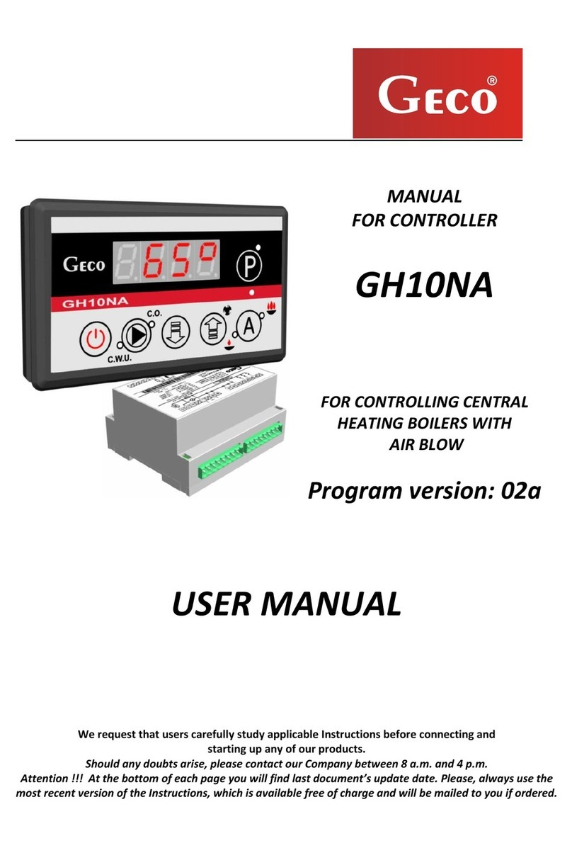
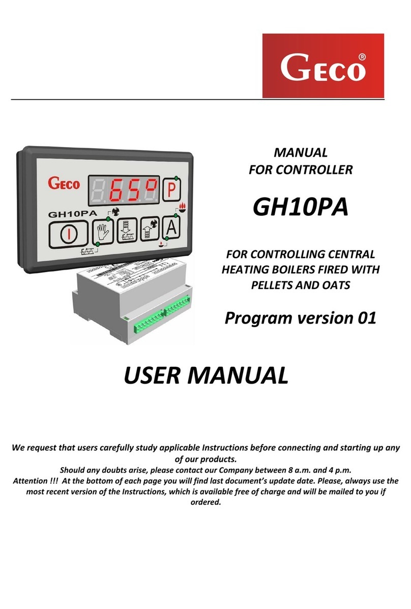
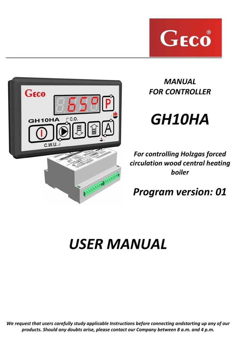
Geco GH22PB User manual

INSTRUCTIONS
FOR
CONTROLLER
GH22PB
FOR
CONTROLLING
CENTRAL
HEATING
BOILERS FIRED
WITH PELLETS
AND OATS
USER MANUAL
We strongly recommend that you familiarise yourself fully with the contents of this manual
before installing and using any of our devices. If you have any questions, please contact us
between 08:00 and 16:00

User Instructions for GECO GH22PB controller
______________________________________________________________________________
Page 2 Edition I November 2014
Table of contents
1.
DESCRIPTION OF CONTROLLER ..........................................................................................................................3
2.
TECHNICAL SPECIFICATIONS...............................................................................................................................3
3.
REQUIREMENTS FOR ELECTRICAL INSTALLATION....................................................................................................4
4.
GRAPHIC AND TEXT DESCRIPTIONS OF DRIVER CONNECTION................................................................................4
5.
CONTROLLER MODES................................................................................................................................................6
5.1.
S
TANDB MODE
.................................................................................................................................................7
5.2.
A
UTOMATIC MODE
–
F
IRING UP
..............................................................................................................................7
5.3.
A
UTOMATIC MODE
-
H
EATING
................................................................................................................................7
5.4.
A
UTOMATIC MODE
-
SUSTAIN
.................................................................................................................................8
5.5.
M
ANUAL MODE
...................................................................................................................................................8
5.6.
A
LARM
/
WARNING MODE
....................................................................................................................................9
6.
OPERATING THE CONTROLLER.........................................................................................................................10
6.1.
C
ONTROLLER FASCIA PANEL
.............................................................................................................................10
6.2.
O
PERATING THE CONTROLLER
–
MAIN SCREEN
..................................................................................................11
6.3.
P
REVIEW OF S STEM OPERATIONS
....................................................................................................................11
6.4.
H
ELP BUTTON
....................................................................................................................................................12
6.5.
M
ANUAL MODE
.................................................................................................................................................13
6.6.
C
ONTROLLER MENU
–
G
RAPHIC TREE
................................................................................................................14
7.
DESCRIPTION OF ADDITIONAL FUNCTIONS ...................................................................................................20
7.1.
DHW
PRIORIT
(
HOT WATER
)........................................................................................................................20
7.2.
S
UMMER FUNCTION
..........................................................................................................................................20
7.3.
A
NTI
-
LEGIONELLA FUNCTION
............................................................................................................................20
7.4.
GA03HA
ROOM PANEL
....................................................................................................................................21
7.5.
S
TANDARD ROOM TERMOSTAT
.........................................................................................................................22
7.6.
F
UEL FEEDER TEMPERATURE DETECTION
..........................................................................................................23
7.7.
B
OILER EXTINGUISHED DETECTION
...................................................................................................................23
7.8.
A
NTI
-S
TOP FUNCTION
......................................................................................................................................24
7.9.
S
TANDARD MODE
.............................................................................................................................................24
7.10.
G
RID MODE
......................................................................................................................................................24
7.11.
P
UMP ONL MODE
............................................................................................................................................25
7.12.
O
PERATION HISTOR
.......................................................................................................................................25
7.13.
R
EED RELA
....................................................................................................................................................25
8.
S STEM INSTALLATION......................................................................................................................................26
8.1
H
EATING INSTALLATION NUMBER
1..................................................................................................................26
8.2
H
EATING INSTALLATION NUMBER
2..................................................................................................................27
8.3
H
EATING INSTALLATION NUMBER
3..................................................................................................................28
9.
CONTROLLER ALGORITHMS FOR TECHNOLOGICAL DEVICES .....................................................................29
9.1
FIRING UP MODE - FAN, FEEDER, HEADER...........................................................................................29
9.2
HEATING MODE – FAN...............................................................................................................................30
9.3
HEATING MODE – FEEDER .......................................................................................................................30
9.4
MAINTAIN MODE – FEEDER AND FAN....................................................................................................31
9.5
CH PUMP – FIRING UP, HEATING, MAINTAIN MODE. ..........................................................................31
9.6
DHW/MIXER PUMP – FIRING UP, HEATING, MAINTAIN MODE. ........................................................31
9.7
CONTAINER FEEDER – FIRING UP, HEATING, MAINTAIN MODE. ......................................................31
10. ALARMS...................................................................................................................................................................32
11.
TEMPERATURE LIMITER (STB). ...................................................................................................................38
12.
LOSS OF POWER ..............................................................................................................................................39
13.
INFORMATION REGARDING THE LABELING AND DISPOSAL OF WASTE ELECTRONIC AND
ELECTRICAL EQUIPMENT ............................................................................................................................................39

User Instructions for GECO GH22PB controller
______________________________________________________________________________
Page 3 Edition I November 2014
1. Description of controller
The GH22PB controller is assembled using microprocessor techniques utilizing automatic
surface mounting.
This controller is a device used to control the process of preparing domestic hot water (the
HW circuit), and provides support for the main circuit (circuit CH). Parameters can be adapted
according to the condition and the type of boiler.
The controller is equipped with a system to guard against power failure and various types of
interference. The controller identifies each emergency and gives a visual and audio warning.
The controller automatically supports three installation configurations, which meet the
requirements of the installer fully. The device supports four temperature sensor inputs (one
PT1000 sensor), optical input for flame sensor (option), standard thermostat , additional output
for room panel GA03HA GECO , and five outputs for external devices.
2. Technical specifications
Supply voltage 230V
~
+10% -15%
Resistance
characteristics of NTC
sensor
Resistance
characteristics of
PT1000 sensor
Operating temperature od +5°C do +40°C
Humidity od 20% do 80% RH
Temp.
°C
Re
sistance
Ω
Temp.
°C
Re
sistance
Ω
Fuse – Fan, Feeder 3,15A 0 7174,89 0 1000,00
Sensor type NTC 2,2kΩ; PT1000 10 4374,83 50 1194,00
Sensor temperature
operating range NTC: 0°C÷100°C
20 2747,10 100 1385,10
PT1000:
0°C÷400°C
30 1774,91 150 1573,30
40 1172,09 200 1758,60
50 795,08 250 1941,00
Input Maximum continuous
load 60 547,95 300 2120,50
70 384,62 350 2297,20
DHW P./Mix P./Feeder
1A 250W 80 275,86 400 2470,90
CO Pump 1A 250W 90 202,37 450 2641,80
Fan* 1A 250W 100 149,16 500 2809,80
Feeder* 1A 250W 550 2974,90
Lighter 3A 750W 600 3137,10
*When a contactor or relay proxy is connected, use a dedicated blowout
system (eg varistor). Omission of this security measure may result in
malfunction or damage to the controller output.

User Instructions for GECO GH22PB controller
______________________________________________________________________________
Page 4 Edition I November 2014
3. Re uirements for electrical installation
WARNING!
Only a person with a valid license to carry out electrical installation work can install the controller
wiring and connection technologies. It is recommended that the work is carried out by a qualified
installation engineer. The following are the basic requirements for the electrical power supply for
this particular controller:
1. Repairs, maintenance and other work on the system can be carried out only after
disconnecting the main power supply.
2. The room in which the controller is to be installed should be equipped with 230V/50Hz
electrical system in accordance with the applicable regulations.
3. The controller should be supplied from a dedicated circuit 230VAC/50Hz grid, protected by
a circuit breaker.
4. The controller power cable should have a cross section minimum mechanical strength of
1.5 [mm2]
5. The cable must be protected from mechanical damage, by keeping it in a duct or housing
4. Graphic and text descriptions of driver connection
When the cable has been prepared, you will be ready to connect the power to the controller
and temperature sensors, thermostats and other devices:
•The 230 V power supply should be connected to the controller using the terminals marked “L”
and “N”.
•The NTC temperature sensor must be connected to the inputs in accordance with the
instructions set out in the tables in section 8: “System Installation”. Please note that the
number of sensors supported depends on the type of installation, and unused sensors do not
have to be connected to inputs.
•Flame sensor, standard thermostat and reed relay must be connected to the inputs in
accordance with the instructions set out in the tables in section 8: “System Installation”.
•The room panel GA03HA must be connected to a separate input, as described.
•Technological equipment (pumps / fan / feeders and lighter) should be connected to the
outputs, as described in the tables in section 8, System Installation and according to the
selected installation

User Instructions for GECO GH22PB controller
______________________________________________________________________________
Page 5 Edition I November 2014
Input parameters are described in the following tables:
Description of controller inputs – temperature sensors
Temperature sensor Type of input Controller designation
Water flowing from
the boiler NTC 0- 1
Fuel Feeder NTC 2- 3
Flue gas PT1000 4-
Water in the DHW
boiler*/ Return temp.* NTC 6- 7
Description of controller inputs – room thermostat
Type of room
thermostat Type of input Controller designation
GA03HA dedicated
room panel - GECO RS48 8- 9-60-61
Standard thermostat - 2- 3
Description of controller inputs – digital
Flame sensibility
sensor on the grate
Type of input Controller designation
Flame sensor*
Optical sensor 6- 7
Reed relay*
Optical sensor 6- 7
*Only in particular schema
Description of controller outputs – technological equipment
Device installed Type of input Controller designation
Lighter Relay 03-04
CH pump Relay 0 -06
DHW pump/
Mix pump/
Feeder burner
Relay 07-08
Feeder** TRIAC 09-11
Fan TRIAC 12-14
**The type of feeder is depend of schema which were choose.

User Instructions for GECO GH22PB controller
______________________________________________________________________________
Page 6 Edition I November 2014
ONLY A QUALIFIED WIRING TECHNICIAN MAY
CONNECT DEVICES TO THE GH22PB CONTROLLER.
5. Controller modes
The controller can be operated in five modes:
•Standby – returns the controller to the state before loss of power. The controller algorithm is
not implemented, the clock operates in real time, and the chosen installation settings are
stored.
•Automatic - There are two sub-modes, heating and sustaining
Firing up - this is the first step of automatic mode, precede heating mode.
Heating – in this mode, the algorithm is implemented in the control mode selected depending
on the type of fuel and heating installations requirements.
Sustaining - the controller enters this mode if the boiler temperature reaches the set point. In
this mode, an individually prepared algorithm is implemented.
Sustain Room - the controller enters this mode if the boiler temperature is block by room
thermostat or room panel GA03HA.
•Manual – This mode is used only to validate the on / off (tests) for each installation of
technological equipment, so when you are sure that tests are finished, go to the automatic
mode.
•Alarm – Characterised by the occurrence of an alarm that prevents further operation of the
equipment or the occurrence of a warning, which allows the user to accept temporary
operation under warning conditions accepted by the user with the awareness that it is
temporary in nature. When the fault is resolved, the driver returns to the mode it was in
before.

User Instructions for GECO GH22PB controller
______________________________________________________________________________
Page 7 Edition I November 2014
5.1. Standby mode
After the installation procedure described in the previous chapter, the GH22PB driver is
turned on standby. In this mode, the screen displays a message about how to select automatic or
manual mode.
When the controller is in standby mode, you can switch to manual mode using the button
. uring normal operation, it is possible to return the controller to standby mode at any time,
by pressing the button .
In standby mode, all outputs and the alarm sound signal are disabled. When the controller is
switched to automatic mode, the display shows the actual temperature of the water in the boiler,
the set temperature, and information about the controller mode.
5.2. Automatic mode – Firing up
The first step in automatic mode is firing up. Firing up controls the fuel feeder, fan and heater in
such a way that the device goes straight into automatic mode (if the parameter S34=0, the igniter
switch cycle is ignored – the controller does not support heater ignition)
Commencement and completion of firing up is dependent on the sensitivity of the flame, and the
retort is read by an optical flame sensor.
After three failed attempts to ignite the boiler flame, alarm number 14 – flame extinguished –
is activated. The controller operating in automatic mode will signal ‘firing up’ with text information
in the top part of the screen – ‘Firing up’. The firing up mode is active only in standard regulation.
5.3. Automatic mode - Heating
In automatic mode, the controller implements the control algorithm for the chosen heating
schema, according to the heating regulation option chosen. Basic information about the system,
displayed on the main screen, includes current and set boiler temperature, and operating mode.
The user may choose from three heating regulation options: Standard, grid mode and pump only.

User Instructions for GECO GH22PB controller
______________________________________________________________________________
Page 8 Edition I November 2014
In automatic heating mode, the controller displays text information in the top part of the screen:
HEATING – when the standard regulation option is set
GRID MODE H– when the grid mode option is set
PUMP ONLY – when the pump only mode is set
A detailed description of non-standard heating regulation options can be found in section 7.
5.4. Automatic mode - sustain
The controller enters this mode if the temperature in the boiler reaches that set by the user in
the parameters menu. The fuel feeder and fan are disabled, for the time set by the user in the
‘sustain time’ parameter.
The controller will exit sustain mode and return to automatic mode, if the temperature of
the boiler falls below the value set in installation parameter ‘boiler temperature hysteresis’, which
can be edited by the user. The central heating pump works in the same way as in automatic mode.
When working in automatic mode sustain, text information is shown in the top part of the
screen:
MAINTAIN – when the standard option is set
SUSTAIN ROOM – when controller is block by thermostat or room panel GA03HA
GRID MODE M– when grid mode is set
In the PUMP ONLY mode maintain mode not exist.
A detailed description of non-standard heating regulation options can be found in section 7.
5.5. Manual mode
In manual mode, the controller does not implement the control algorithm, and the number and
type of technological devices connected is dependent on the user, who takes responsibility for the
correct operation of the equipment. On the main screen, the actual and set boiler temperature is
always displayed. The choice of heating regulation option does not affect the operation of the
system in manual mode. In this case, the user has full control over what equipment will be
operated by the controller.

User Instructions for GECO GH22PB controller
______________________________________________________________________________
Page 9 Edition I November 2014
After entering the manual mode, operation of all equipment will be stopped automatically. The
controller working in automatic mode displays text information at the top of the screen –
‘MANUAL MO E’.
5.6. Alarm/warning mode
Alarm - The controller goes into alarm mode when one of the required sensors fails or is
disconnected, or when the cable is broken. The controller will signal that the sensor in
question is required. When the fault is repaired, the controller returns to the mode it was in
before. The controller will not enter alarm mode when the sensor fault has been repaired. Any
changes to components should be done with the controller turned off.
Warnings - The controller switches to warning mode when the DHW/returning sensor fails
or is disconnected, or when the cable is broken. The controller then gives information about
the warning, and the types of operations conditionally possible without the sensor. The user
must always accept operations that are conditional on the lack of sensor, each time the
controller is restarted. This applies only to those sensors which do not affect the safe
operation of the heating system. After repairing the sensor problem or removing the cause of
the interference, the controller returns to the mode in which it was previously operating. Any
changes to components should be made with the controller turned off.
The other functions of the warning mode are to give information when the hot water tank has
not been disinfected, or the temperature in the feeder has not been raised. The controller exits
the warnings mode when one of the warnings is UW10 or UW17.
All service like changing sensor or device, should be perform when the controller is switch off.
When the user accept controller emergency work conditionally possible without the sensor, the
controller inform user about problem to resolve by show exclamation mark in the bottom
center of the display. The mark disappear when sensor is fix.

User Instructions for GECO GH22PB controller
______________________________________________________________________________
Page 10 Edition I November 2014
6. Operating the controller
Operating the controller is described in this chapter. It includes turning it on, using the
keyboard, a working preview of the measuring system, reading text or characters on the
screen, and editing the parameters available to the user.
6.1. Controller fascia panel
Button
Description
Function
Turn on/off The main screen appears
Change modes
Switch between manual and automatic
In the ‘boiler mode bar’, Manual
Mode appears, or in the case of
Automatic Mode.
Automatic mode allows a view of devices,
temperature and accompanying features.
In manual mode, view temperature and
accompanying features, and see devices
which can be dited.
The screen shows temperature,
devices and accompanying features
From the main screen, go to the user help
menu.
From the alarm and warnings screen, go
to Data service
The screen shows help for users.
The screen shows product
information and service helpline
information.
Confirm change.
Enter Menu from the main screen
Saves change
Goes to Menu from the main screen
Exit without confirming changes.
Hold the button for three seconds to go to
the main screen
Exit to previous screen or higher
level menu
Right arrow
Quickly go to boiler output temperature
screen from the main screen.
Move to the next column or row on
the right. The screen displays boiler
output temperature.
Left arrow
Quickly go to boiler output temperature
screen from the main screen.
Move to the next column or row on
the left. The screen displays boiler
output temperature.
Up arrow
Increase value
Go to the next position above
Increase the value by one step
Down arrow
Decrease value
Go to the next position below
Decrease the value by one step

User Instructions for GECO GH22PB controller
______________________________________________________________________________
Page 11 Edition I November 2014
6.2. Operating the controller – main screen
When first connected to a power source, the controller turns on in standby mode. The
function button is used to turn the controller on/off, and to move from standby to
manual mode.
⇒
6.3. Preview of system operations
The controller offers a quick preview of system operations. When you press the button in
any mode, you can preview all the major parameters of the controller, temperature measured by
the controller, device status, and active / inactive control functions.
Shows controller
working in safe
mode
Directional
keys, for
changing
values
Current boiler
temperature or
returning
temperature,
according to the
selected system
Set boiler
temperature
Boiler mode
FIRING UP
HEATING
MAINTAIN
MANUAL MODE
GRID MODE
PUMP ONLY
GRID MODE M
SUSTAIN ROOM
Current boiler
temperature

User Instructions for GECO GH22PB controller
______________________________________________________________________________
Page 12 Edition I November 2014
All information on the work of the heating system are divided into categories and placed on
separate screens. Move between the screens by using the buttons . At the bottom of
every screen there is a text description of the item. Move between items on the screen using the
buttons .
The curser shows the position on the screen. The current device is shown by the negation of
the icon corresponding to the device. Current additional functions are shown in the same way.
System temperature preview is possible in all controller modes. In the manual mode, it is also
possible to switch devices on and off.
6.4. Help button
Using the button from the main screen opens the help menu, from where the user can get
service information and descriptions of all icons displayed on the controller’s screens.

User Instructions for GECO GH22PB controller
______________________________________________________________________________
Page 13 Edition I November 2014
Basic information about the boiler and controller manufacturer is available:
All of the controller’s icons are described in text:
USING THE BUTTON FROM ALARM MODE TAKES YOU TO SERVICE
INFORMATION. THE FOLLOWING IS DISPLAYED ON THE SCREEN: CONTROLLER
MODEL, PROGRAMME NUMBER, AND TELEPHONE CONTACT DETAILS FOR THE
MANUFACTURER OR TECHNICIAN.
6.5. Manual mode
Pressing the button in automatic mode switches the controller to manual mode, and
immediately stops all devices. In this mode, the user can manually turn on/off the lighter, fan,
feeder, heating pump and hot water pump, independently of each other. To do this, press the
button which will open the screen for editing the devices.
After moving to the desired position on the screen, according to the information text at the
bottom, using the button will switch on and off the selected device. The cursor shows the
position on the screen. The device to be switched on or off is indicated by a backlit icon.

User Instructions for GECO GH22PB controller
______________________________________________________________________________
Page 14 Edition I November 2014
MENU
Operation record
User settings
Boiler temperature
Temperatura
DHW/Return
Fan speed
Feeder working
time
Installation settings
Configuration
layout
Hot utility water
(optional)
Summer mode
(optional)
Feeder stop
time
Controller panel
setting
Choose language
Date and time
Anti-Legionella
(optional)
Maintain time
Alarms and
warnings
Boiler run time
Emergency work
time
Exceeding
maximum
temperature
Display selection
Standard
Profile 1
Control mode
Standard
Fire grid mode
Anti-stop function
Standard
Complete
Inactive
Power supply
outage
Pump only
Factory settings
Boiler temperature
hysteresis
DHW temperature
hysteresis (optional)
6.6. Controller menu – Graphic tree

User Instructions for GECO GH22PB controller
______________________________________________________________________________
Page 15 Edition I November 2014
6.6.1 User settings
Description of user settings parameters Min Min
Factory
settings
Set boiler temperature 'S3' 'S4' 50°C
Set DHW temperature (optional) 35 65 40°C
Set returning temperature (optional) 40 60 50°C
Fan speed 1 10 5
Feeder operation time 2 250 15s
Feeder operation interval time 5 250 45s
Sustain time 1 250 5min
•Set boiler temperature – Temperature that the boiler will reach. The range is from ‘S3’
parameter to ‘S4’ parameter. Temperature set up in the room panel GA03HA is overriding.
•Set DHW temperature – Temperature to which the boiler will rise. This parameter is
available for users only when the DHW (temp DHW)/additional mixer pump (temp
returning) option is selected. The range is from 3 °C to 6 °C.
•Set returning temperature – Temperature which is returning to the boiler from the
layout. This parameter is available for users only when the additional mixer pump (temp
returning) option is selected. The range is from 40°C to 60°C.
•Fan speed – This parameter sets the fan speed, i.e., the amount of air supplied. It allows the
selection of fan speed depending on the quality and type of fuel used.
The range is from 1 to 10.
•Feeder operation time – This parameter describes the length of time that the fuel feeder
is connected in HEAT mode, in standard setting. The range is from 2 s to 2 0 s.
•Feeder operation interval time – This is the interval between each supply of fuel to the
boiler in HEATING mode. The range varies from s to 2 0 s. Only available in standard
setting.
•Sustain time – The time after which the controller switches on the fan and feeder,
specified by the manufacturer to prevent the boiler shutting down in sustain mode. The
range is from min to 2 0 min.

User Instructions for GECO GH22PB controller
______________________________________________________________________________
Page 16 Edition I November 2014
6.6.2 Installation settings
Description of installation parameters Min Min
Factory
settings
System configurations:
(1) - K1: Boiler + CH + CONTAINER FEEDER*
(2) - K2: Boiler + CH + DHW
(3) - K3: Boiler + CH + Mixer
1 3 1
DHW priority (optional) No Yes No
Summer mode (optional) No Yes No
Anti-Legionella (optional) No Yes No
Factory settings No Yes -
Boiler temperature hysteresis 2 10 3°C
Temperature hysteresis of DHW/returning (optional) 2 10 5°C
Regulation option:
(1) - Standard
(2) – Fire grid mode
(3) – Pump only
1 3 1
Anti-stop function:
(1) - Standard
(2) - Complete
(3) - Inactive
1 3 1
*Operating the feeder container is run by adjust value of service parameter
•System configuration – Allows selection of the heating system operated by the controller,
with an additional pump or without. A description of the system is in section 8.
•DHW priority – Activating the function makes water heating the primary function of the
Controller. A description of the functions in section 7.
•Summer mode – This function turns off the central heating pump and the boiler operates
only to heat water. A description of this function is in section 7.
•Anti-legionella – This is aimed at limiting the growth of bacteria of the genus legionella
pneumophila in the hot water. A description of this function is in section 7.
•Factory settings – restore all user and service parameters in the controller.
•Boiler temperature hysteresis – value of the boiler temperature hysteresis, at which
sustain mode is exited and heat mode is resumed.
•DHW temperature hysteresis – value of DHW temperature hysteresis, at which the pump
returns to hot water mode, or exits sustain mode.
•Regulation option – Allows customisation of the system operation algorithm according to
type of fuel and technical capabilities. A description of this function is in section 7.
•Anti-stop function – Allows a security function for connected devices, which guards
against system deterioration during the summer months. A description of this function is in
section 7.

User Instructions for GECO GH22PB controller
______________________________________________________________________________
Page 17 Edition I November 2014
6.6.3 Operation history
Operation history is where information on all controller malfunctions and custom activities
is stored. All failures and irregularities identified by the programme are stored and archived
according to whether they are alarms or warnings.
Operation history menu:
Additional information is stored to help the user or service technician identify any
irregularities in system operation. The types of events recorded in operation history are:
Alarms and warnings – The controller can store the last 8 alarm conditions detected. Alarms
and comments are displayed in a chronological list, with the most recent at the top. Alarms
are indicated with the symbol AL, and warnings with UW, along with information about the
type of problem and the date and precise time at which it occurred.
All new alerts appear on the operation history list alongside an envelope icon, indicating an
‘unread’ alert that needs the attention of the user or a service engineer. The envelope icon
disappears when the alert has been read.

User Instructions for GECO GH22PB controller
______________________________________________________________________________
Page 18 Edition I November 2014
Boiler operating time - The screen shows the operating time, in automatic heating and
sustain mode. The time is measured by the hour [h].
Emergency work time – The screen shows safe mode operating time, without breakdown of
feeder and fan, measured by the hour [h].
Exceeding maximum temperature – The screen shows the number of times the maximum
temperature of 8 °C has been exceeded, displayed in number of incidences.
Power failure – The screen shows the number of times that power to the controller has
failed, displayed in number of incidences.

User Instructions for GECO GH22PB controller
______________________________________________________________________________
Page 19 Edition I November 2014
6.6.4 Controller settings
Settings for the controller, which do not effect heating system operations, can be found in the
controller settings panel.
Controller settings parameters:
Choose language – The controller allows the user to choose from one of several language
settings.
Date and time – In order to ensure that all of the controller functions work correctly and at
the optimum level, set the correct time and date.

User Instructions for GECO GH22PB controller
______________________________________________________________________________
Page 20 Edition I November 2014
Choose screen – The user can set a personal profile screen, and customise the type of
information that will be shown. The settings menu offers several choices, with ‘standard’ set by
default.
7. Description of additional functions
7.1. DHW priority (hot water)
The GH22PB controller can be set to pump hot water as a priority. If you select this mode,
water heating becomes the primary function of the controller, with heating (CH) secondary.
This is only available in the second configuration. To enable this function, set the value to
"yes" in the menu.
To enable this function, set the value to ‘ ES’ in the main menu.
7.2. Summer function
The GH22PB controller is equipped with a summer mode, which can be used in the
summer to turn off the CH pump so that the boiler only heats water. For this function to work,
a system installation supporting a DHW pump must be selected. This is only available in the
second configuration.
To enable this function, set the value to ‘ ES’ in the main menu.
7.3. Anti-legionella function
The controller is equipped with an Anti-legionella function, aimed at limiting the growth of
bacteria of the genus legionella pneumophila in the hot water.
Legionella bacteria develop in aqueous environments, and the optimum temperature for
their growth is from 38-42 C. These bacteria also contribute to blockages in hot water
systems, hot water heaters and tanks. Legionella bacteria cause a non-specific variant of
pneumonia known as Legionnaires' disease, or legionellosis. Legionellosis has been officially
recognised by the Ministry of Health as an infectious disease.
The anti-legionella function performed by the GH22PB controller aims to ensure that the
hot water tank is not a favourable environment for legionella bacteria.
Table of contents
Other Geco Controllers manuals