P.10
Installation Instructions
Attention
- The heater must be installed and repaired by qualified technicians.
- Before installation, you must switch off the electricity at the circuit breaker.
- Do not install the heater on the ceiling or in a tilted position.
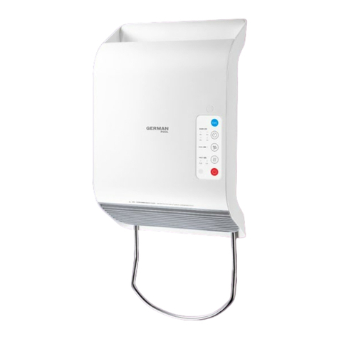
- The heater must be wall-mounted in the horizontal position.
- Do not mount vertically. This would cause damage to the heater and the warranty would be disqualified.
- Do not install the heater below a wall socket.
- Ensure the heater is installed at least 60cm from any flammable objects (e.g. curtains, clothes).
- Remove the support packaging before using the heater.
- To avoid any damage on the enamel surface, do not press or hit on the front housing of the heater
during installation.
Electrical Supply Requirements
- Before using the heater for the first time, check that the supply voltage of your installation complies
with the voltage marked on the heater.
- The heater should be wired using 3-core 1.5mm2cable. To comply with regulations, the supply
wiring for this heater must be provided with a means of isolation, which gives a contact separation
of at least 3mm in both the line and neutral poles. It is therefore recommended that the
cable feeding the heater should be connected to a switched fused connection unit (to BS 1363
Part 4), which should be situated in a convenient position close to the heater.
- Do not connect the heater to a lighting supply circuit.
Installation
1. Bathroom Installation – a minimum distance (horizontal) of not less than 60cm must be
maintained between the nearest edge of a bath/shower and heater. If the size of the bathroom
does not allow this, the heater should not be installed in the room, as this would impair the
user’s safety.
2. Choose a suitable position on the wall so that there is no hidden pipe or cable in the same
location. The heater should be mounted at a minimum height of 2m from the floor. Clearance
between ceiling or adjacent walls shall be a minimum of 200mm from the heater. Mark the
position of the two screw holes at a distance of 250mm on the wall with the heater in a
horizontal position. Drill the wall 30mm deep using a suitably sized masonry drill for the wall
plugs or screws supplied.
3. Remove the terminal cover by unscrewing the two retaining screws along the top edge
of the fixing bracket.
4. The two angle-adjusting screws located at each end of the terminal box assembly should
now be loosened slightly. The body of the heater will tilt forward, allowing full access
to the fixing screws with a screwdriver. Using the screws and wall plugs supplied,
mount the heater to the wall by means of the fixing bracket. Do not over tighten the
fixing screws.
If there is no wall outlet close to the place where heater is installed, please take
the following steps instead:
a) Carefully remove 50mm of the outer sheath of the supply cord. Measure and cut the
live (coloured red or brown) and neutral conductors (coloured blue or black) to 40mm.
Remove 6mm of insulation from the ends of all three conductor ends. Feed into
the unit through one of the grommets (at the ends of the fixing bracket) so that
the free end can easily reach the terminals.
b) Connect the cords of the incoming supply cable as follows:
The Neutral wire (coloured black or blue) must be connected to the terminal marked N.
The Live wire (coloured red or brown) must be connected to the terminal marked L.
The Earth wire (coloured green and yellow) must be connected to the terminal
marked with the earth symbol.
Ensure that the connections are tightened firmly. Refit terminal cover to ensure
that insulation material wraps over terminal block assembly.
5. Swing the body of the heater up to near the vertical position, in order to enable the tab
on the bottom edge of the body to fit behind the terminal cover. Fit the terminal cover
in position ensuring that the tabs on the bottom edge are positioned behind the lower
lip of the aperture and replace the two terminal cover retaining screws.
6. Set the heater in the position at desired angle. Tighten the two angle adjusting screws.
7. Switch on the circuit breaker or replace the fuse to restore power to the heater.
Installation Instructions

