GiBiDi SC380 Guide

SC380
UK
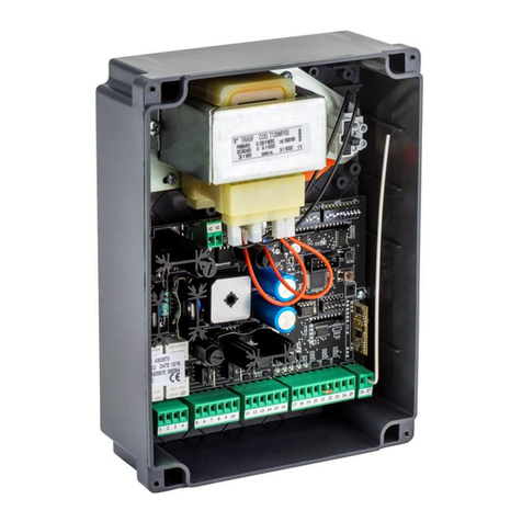
SC380 (AS05800 - AS05810) Electronic control unit
INSTRUCTIONS FOR INSTALLATION

SC380
2SC380 3
UK UK
PLEASE READ CAREFULLY THIS MANUAL BEFORE PROCEEDING WITH THE INSTALLATION.
This product has been tested by GI.BI.DI., checking the perfect correspondance of its characteristics to the current
directive.
GI.BI.DI. S.r.l. reserves the right to modify the technical data without prior notice, depending on the product
development.
WARNING
230 Vac
42 43 44
M12
J1 J2
42 43 44
M12
J1 J2
380 Vac
The control unit is provided without jumper for the selection of the supply voltage.
Before powering the control unit, it is necessary to make a jumper on terminal M12, according to the supply voltage
you want to use.
( AS05800 )
316
236
128
236
316
( AS05810 )
128
DIMENSIONS
1

4 5
SC380 SC380
UK UK
TRANSFORMER ELECTRICAL CONNECTIONS
42 43 44
M12
F1
J1 J2 J3 J4 J5 J6 J7
TR3 RL7
JP1
RL6
MCU
RX CONNECTOR
380
220
0
14 Vac 22 Vac
0
220 Vac
380 Vac
F4
F3
F2
TR2
RL8
RL5
1 A
6 A
BLACK
GREY
BROWN RED
BLUE
14 Vac 22 Vac
3
INSTALLATION
2
170
250

4 5
SC380 SC380
UK UK
TRANSFORMER ELECTRICAL CONNECTIONS
42 43 44
M12
F1
J1 J2 J3 J4 J5 J6 J7
TR3 RL7
JP1
RL6
MCU
RX CONNECTOR
380
220
0
14 Vac 22 Vac
0
220 Vac
380 Vac
F4
F3
F2
TR2
RL8
RL5
1 A
6 A
BLACK
GREY
BROWN RED
BLUE
14 Vac 22 Vac
3
INSTALLATION
2
170
250

6 7
SC380 SC380
UK UK
COLLEGAMENTO CON 380 Vac 3 FASI / POWER SUPPLY 380 Vac 3 PHASES
5
ELECTRICAL CONNECTIONS ( AS05800 )
5 6 78
1 2 34910 11 15 16 17 18 19 20 21 22 23 24 25 26 27 28 29
30 31 32 33 3534 36 38
37 39 40 41
42 43 44
PED (NO)
START (NO)
FCA (NC)
PHOTO 2 (NC)
RISERVA (NO)
SAFETY 1 (NC)
PHOTO 1 (NC)
COM
FCC (NC)
OPEN (NO)
CLOSE (NO)
SAFETY 2 (NC)
STOP (NC)
COM
PHASE ( R )
PHASE ( S )
PHASE ( T )
COM
EARTH
EARTH
M
LAMP
LAMP
M1 M2 M3 M4 M5
M6
M7
M10
M9 M11
M8
M12
F1
F4
F3
F2
J1 J2 J3 J4 J5 J6 J7
+
OK
ESC
-
RL1 RL2
TR3
TR2
TR1
RL8
RL3 RL4
RL5
RL7
JP1
RL6
MCU
RX CONNECTOR
DL1
DL2
DL3
DL4
DL5
DL6
DL7
DL8
DL9
DL10
230Vac 40W MAX
M10
M9 M11
30 31 32 33 3534 36 38
37 39 40 41
24Vdc 3W MAX
+24Vcc
+24Vcc E-SAV
INDUCTIVE SENSOR
+24Vcc
COM
OPT
S3
S4
S1
S2
LED STATUS
ON
OFF
COM
CLOSE
OPEN
12 13 14
DL11
MENU E32
MENU E34
REL1
REL2
4
ELECTRICAL CONNECTIONS ( AS05810 )
5 6 78
1 2 34910 11 12 13 14 15 16 17 18 19 20 21 22 23 24 25 26 27 28 29
30 31 32 33 3534 36 38
37 39 40 41
42 43 44
M1 M2 M3 M4 M5 M6 M7
M10
M9 M11
M8
M12
F1
F4
F3
F2
J1 J2 J3 J4 J5 J6 J7
+
OK
ESC
-
RL1 RL2
TR3
TR2
TR1
RL8
RL3 RL4
RL5
RL7
JP1
RL6
MCU
RX CONNECTOR
DL1
DL2
DL3
DL4
DL5
DL6
DL7
DL8
DL9
DL11
PED (NO)
START (NO)
FCA (NC)
PHOTO 2 (NC)
RISERVA (NO)
SAFETY 1 (NC)
PHOTO 1 (NC)
COM
FCC (NC)
OPEN (NO)
CLOSE (NO)
SAFETY 2 (NC)
STOP (NC)
COM
PHASE ( R )
PHASE ( S )
PHASE ( T )
COM
EARTH
EARTH
LAMP
LAMP
230Vac 40W MAX
MENU E32
MENU E34
M10
M9 M11
30 31 32 33 3534 36 38
37 39 40 41
24Vdc 3W MAX
+24Vcc
+24Vcc E-SAV
INDUCTIVE SENSOR
+24Vcc
COM
OPT
S3
S4
S1
S2
LED STATUS
ON
OFF
M
COM
CLOSE
OPEN
DL10
REL1
REL2

8 9
SC380 SC380
UK UK
7
230 Vac 3 PHASES POWER SUPPLY
230 Vac
230 Vac
12 13 14
5 6 78
1 2 34910 11
PHASE ( R )
PHASE ( S )
PHASE ( T )
EARTH
EARTH
LAMP
LAMP
M1 M2 M3 M4 M5
M6
RL1 RL2
230Vac 40W MAX
M
COM
CLOSE
OPEN
230 Vac
5 6 78
1 2 34910 11
EARTH
EARTH
LAMP
LAMP
M1 M2 M3 M4 M5
RL1 RL2
230Vac 40W MAX
12 13 14
M6
PHASE ( R )
PHASE ( S )
PHASE ( T )
M
COM
CLOSE
OPEN
( AS05810 )
( AS05800 )
42 43 44
M12
J1 J2
MENU E32
MENU E34
REL1
REL2
MENU E32
MENU E34
REL1
REL2
380 Vac 3 PHASES POWER SUPPLY
42 43 44
M12
J1 J2
380 Vac
380 Vac
12 13 14
5 6 78
1 2 34910 11
PHASE ( R )
PHASE ( S )
PHASE ( T )
EARTH
EARTH
LAMP
LAMP
M1 M2 M3 M4 M5
M6
RL1 RL2
230Vac 40W MAX
M
COM
CLOSE
OPEN
380 Vac
5 6 78
1 2 34910 11
EARTH
EARTH
LAMP
LAMP
M1 M2 M3 M4 M5
RL1 RL2
230Vac 40W MAX
12 13 14
M6
PHASE ( R )
PHASE ( S )
PHASE ( T )
M
COM
CLOSE
OPEN
( AS05810 )
( AS05800 )
MENU E32
MENU E34
REL1
REL2
MENU E32
MENU E34
REL1
REL2
6

10 11
SC380 SC380
UK UK
9
EARTH CONNECTION
10
380 Vac 3 PHASES MOTOR CONNECTION
53 4
M
M2
COM
CLOSE
OPEN
PHASE ( R )
PHASE ( S )
PHASE ( T )
380 Vac
1 2
M1
EARTH
EARTH
11
12
230 Vac 3 PHASES MOTOR CONNECTION
230 Vac 1 PHASE MOTOR CONNECTION
230 Vac
53 4
M
M2
PHASE ( R )
PHASE ( S )
PHASE ( T )
COM
CLOSE
OPEN
M2
230 Vac
53 4
M
PHASE ( R )
NEUTRAL ( N )
PHASE ( R )
COM
CLOSE
OPEN
FLASHING LIGHT CONNECTION
67
LAMP
LAMP
M3 230 Vac 40W max MENU - C 2
2 on
off
on
off
3 on
off
on
off
Ref
13
8
230 Vac 1 PHASE POWER SUPPLY
42 43 44
M12
J1 J2
230 Vac
230 Vac
230 Vac
12 13 14
5 6 78
1 2 34910 11
PHASE
NEUTRAL
EARTH
EARTH
LAMP
LAMP
M1 M2 M3 M4 M5
M6
RL1 RL2
230Vac 40W MAX
M
COM
CLOSE
OPEN
M
COM
CLOSE
OPEN
5 6 78
1 2 34910 11
EARTH
EARTH
LAMP
LAMP
M1 M2 M3 M4 M5
RL1 RL2
230Vac 40W MAX
12 13 14
M6
PHASE
NEUTRAL
( AS05810 )
( AS05800 )
MENU E32
MENU E34
REL1
REL2
MENU E32
MENU E34
REL1
REL2

12 13
SC380 SC380
UK UK
15
M5 MULTIFUNCTION TERMINAL BLOCK
10 11
M5
MENU - E 34
Rif
on
off
3 sec on
off
3 sec
on
off
3 Min
on
off
on
off
on
off
on
off
on
off
on
off
3 sec
on
off
3 sec
2
3
4
5
6
10 11
M5
10 11
M5
10 11
M5
10 11
M5
3 Min
14
M4 MULTIFUNCTION TERMINAL BLOCK
8 9
M4
MENU - E 32
Rif
on
off
3 sec on
off
3 sec
on
off
3 Min
on
off
on
off
on
off
on
off
on
off
on
off
3 sec
on
off
3 sec
2
3
4
5
6
8 9
M4
8 9
M4
8 9
M4
8 9
M4
3 Min

14 15
SC380 SC380
UK UK
PHOTOCELLS 1 CONNECTION
20
21
24 25 26 27 28 29
PHOTO 2 (NC)
SAFETY 1 (NC)
PHOTO 1 (NC)
SAFETY 2 (NC)
STOP (NC)
COM
M8 M9
30 31 32 33
24Vdc 3W MAX
+24Vcc
+24Vcc E-SAV
23
RXTX
M1
1 2
34
M2
1
COM
23
RXTX
M1
1 2
34
M2
1
MENU - C 40
22
24 25 26 27 28 29
PHOTO 2 (NC)
SAFETY 1 (NC)
PHOTO 1 (NC)
SAFETY 2 (NC)
STOP (NC)
COM
M8 M9
30 31 32 33
24Vdc 3W MAX
+24Vcc
+24Vcc E-SAV
23
RXTX
M1
1 2
34
M2
1
COM
23
RXTX
M1
1 2
34
M2
1
MENU - C 41
23
PHOTOCELLS 1 WITH TEST CONNECTION
PHOTOCELLS 2 CONNECTION
PHOTOCELLS 2 CONNECTION WITH TEST
MENU - C 40 / E1
24 25 26 27 28 29
PHOTO 2 (NC)
SAFETY 1 (NC)
PHOTO 1 (NC)
SAFETY 2 (NC)
STOP (NC)
COM
M8 M9
30 31 32 33
24Vdc 3W MAX
+24Vcc
+24Vcc E-SAV
23
RXTX
M1
1 2
34
M2
1
COM
23
RXTX
M1
1 2
34
M2
1
MENU - C 41 / E 1
24 25 26 27 28 29
PHOTO 2 (NC)
SAFETY 1 (NC)
PHOTO 1 (NC)
SAFETY 2 (NC)
STOP (NC)
COM
M8 M9
30 31 32 33
24Vdc 3W MAX
+24Vcc
+24Vcc E-SAV
23
RXTX
M1
1 2
34
M2
1
COM
23
RXTX
M1
1 2
34
M2
1
REFER TO THE PHOTOCELLS MANUAL FOR DETAILED CONNECTION DIAGRAMS
CONTROL DEVICES CONNECTION
16
MENU - C 4 / C 23
MENU - E 9
LIMIT SWITCHES CONNECTION
17
EXTERNAL CONNECTION CLOCK
18
PED (NO)
START (NO)
FCA (NC)
RISERVA (NO)
COM
FCC (NC)
OPEN (NO)
CLOSE (NO)
COM
15 16 17 18 19 20 21 22 23
M7
15 16 17 18 19 20 21 22 23
PED (NO)
START (NO)
FCA (NC)
RISERVA (NO)
COM
FCC (NC)
OPEN (NO)
CLOSE (NO)
COM
M7
MENU - E 9
ELECTROMAGNETIC DETECTOR CONNECTION ( MMD )
19
PED (NO)
START (NO)
FCA (NC)
RISERVA (NO)
COM
FCC (NC)
OPEN (NO)
CLOSE (NO)
COM
15 16 17 18 19 20 21 22 23
M7
REED
REED
M1
M
M4
M3
5 6 7
5 6 75 6 7
FCA
FCC
COM
MOTOR OPEN
MOTOR CLOSE
MOTOR COM
PED (NO)
START (NO)
FCA (NC)
RISERVA (NO)
COM
FCC (NC)
OPEN (NO)
CLOSE (NO)
COM
15 16 17 18 19 20 21 22 23
M7
DCF180
DCF180
DCF180
DCF180

16 17
SC380 SC380
UK UK
24 25 26 27 28 29
PHOTO 2 (NC)
SAFETY 1 (NC)
PHOTO 1 (NC)
SAFETY 2 (NC)
STOP (NC)
COM
M8 M9
30 31 32 33
24Vdc 3W MAX
+24Vcc
+24Vcc E-SAV
24
COM
MENU - C 42
NC “SAFETY DEVICE 1” CONNECTION
8K2
24 25 26 27 28 29
PHOTO 2 (NC)
SAFETY 1 (NC)
PHOTO 1 (NC)
SAFETY 2 (NC)
STOP (NC)
COM
M8 M9
30 31 32 33
24Vdc 3W MAX
+24Vcc
+24Vcc E-SAV
25
COM
8K2 “SAFETY DEVICE 1” CONNECTION
8K2
NC
NC
NC
24 25 26 27 28 29
PHOTO 2 (NC)
SAFETY 1 (NC)
PHOTO 1 (NC)
SAFETY 2 (NC)
STOP (NC)
COM
M8 M9
30 31 32 33
24Vdc 3W MAX
+24Vcc
+24Vcc E-SAV
26
COM
MENU - C 43
NC “ SAFETY DEVICE 2” CONNECTION
8K2
24 25 26 27 28 29
PHOTO 2 (NC)
SAFETY 1 (NC)
PHOTO 1 (NC)
SAFETY 2 (NC)
STOP (NC)
COM
M8 M9
30 31 32 33
24Vdc 3W MAX
+24Vcc
+24Vcc E-SAV
27
COM
8K2 “SAFETY DEVICE 2” CONNECTION
8K2
NC
NC
NC
MENU - C 42
MENU - C 43
24 25 26 27 28 29
PHOTO 2 (NC)
SAFETY 1 (NC)
PHOTO 1 (NC)
SAFETY 2 (NC)
STOP (NC)
COM
M8 M9
30 31 32 33
24Vdc 3W MAX
+24Vcc
+24Vcc E-SAV
31
COM
MENU - C 44
STOP CONNECTION
M9
30 31 32 33
24Vdc 3W MAX
+24Vcc
+24Vcc E-SAV
29
COM
WARNING LIGHT CONNECTION
3534 36 37
IMP
+24Vcc
COM
OPT
M10
30
MOTOR RPM SENSOR
BLUE
BROWN
BLACK
38 39 40 41
S3
S4
S1
S2
M11
31
2 CONTROL BOARDS SYNCHRONIZATION
38 39 40 41
S3
S4
S1
S2
M11
M8 M9
28

18 19
SC380 SC380
UK UK
1 - SPECIFICATION SHEET
Control unit
Type
Power supply
Line disconnector
N° motors
Motor power supply
Flashing light
Warning light
Electric lock
Accessories power supply
Radio receiver
Operating temperature
Protection degree
Code
Electronic control unit for the automation of one 230Vac or
380Vac motor for swinging, sliding gates or bollards.
SC380
Yes No
1
230Vac Monophase 50/60 Hz
230 / 380Vac Three-phase 50/60 Hz
230Vac 40W max
230Vac Monophase 50/60 Hz
230 / 380Vac Three-phase 50/60 Hz
24Vdc 3W max
Managed by relay with free contact
24Vdc 8W max
Safety devices power supply
Plug-in
-20°C +60°C
IP 55
Safety devices test Yes
Energy saving Yes
AS05800 AS05810
2 - TECNICHAL SPECIFICATIONS AND FUNCTIONS
Red warning leds of NC contacts. There is not the safety devices led (from terminals 24 to 28). See “SIGNALLING
LED” table.
Green warning leds of NO contacts. See “SIGNALLING LED” table.
Management of 1 electric lock by a relay with free contact.
Management of 1 electric magnet by a relay with free contact.
Management of the courtesy light by a relay with free contact.
Safety test run before the opening and closing movement.
Photocell test run before the opening and closing movement.
Motion stop and inversion for 2 seconds after the intervention of the safety devices.
Additional attempts (till 5) after the intervention of safety devices to allow the restart of the motion.
Safety devices test.
Energy saving (ENERGY SAVING).
Digital programming of all functions.
Working time adjustable independently in opening and closing.
Adjustable pedestrian working time.
Adjustable pause time, differentiated for complete or pedestrian opening.
4 possible working functions (step by step, step by step with stop, condominium or automatic, dead man).
Possibility of choosing the system configuration between swinging, sliding gate and bollard.
Setting of 5 safety inputs, selectable as inputs: STOP-RESISTIVE NC-RESISTIVE 8K2-PHOTO1-PHOTO2.
Setting of:
§Automatic closing.
§Fast closing.
§Pre-flashing.
§Hammer stroke.
§Final opening and closing stroke.
§Courtesy light.
§Fixed or intermittent flashing light.
§Reserve input with 3 different operating modes.
§Hydraulic block maintenance.
§Electronic brake.
§Number of cycles for scheduled maintenance.
§Installer password.
Display of the number of cycles done and of the number of power supply days.
Possibility of powering the control unit and 230V monophase 50/60Hz or 230 / 380V three-phase 50/60Hz motor.
Main line switch (disconnector 16A )with door locking device (code AS05800).
Motor braking always active at each stop (if in sliding operator mode).
Synchronism with a different control unit allowed with simplified wiring.
Motor revolutions sensor for obstacle detection and motion inversion.

20 21
SC380 SC380
UK UK
3 - INSTALLATION WARNINGS
protexion degree of the case.
Before proceeding with the installation, it is necessary to fit a magnetothermal and differential switch with a
maximum capacity of 10A upstrem of the system. The switch must guarantee an omnipolar separation of the
contacts, with an opening distance of at least 3 mm.
To prevent possible interference, differentiate and always keep the power cables (minimum section 1,5mm²)
separate from the signal cables (minimum section 0,5mm²).
Make the connections referring to this manual. Connect in series all the devices that must be connected to the
same N.C. (normally closed) input and in parallel all the devices that share the same N.O. (normally open) input.
Incorrect installation or improper use of the product may compromise the safety of the system.
Keep all the matrials contained in the packaging away from children, since they pose a potential risk.
The manufacturer declines all responsibility for improper functioning of the automated device, if the original
components and accessories, suitable for the specific automation, are not used.
At the end of the istallation, always check carefully the proper functioning of the system and the devices used.
This instruction manual addresses people qualified for the installation of “live equipment”. Therefore good
technical knowledge and professional practice in compliance with the regulations in force are required.
Maintenance must be carried out by qualified personnel.
Before carrying out any cleaning or maintenance operation, disconnect the control unit from the mains.
This control unit may only be used for the purpose for which it was designed.
The use of the product for purposes different from the intended use has not been tested by the manufacturer.
Therefore any work is carried out on full responsibility of the installer.
Mark the automated gate with visible warning plates.
Warn the user that children or animals may not play or stand around near the gate.
Appropriately protect the dangerous points (for example, use one or more sensitive edges).
Use suitable cable glands to assure the correct mechanical connection of the wiring and maintain the Ip55
4 - WARNINGS FOR THE USER
In the event of an operating fault or failure, cut the power upstream of the control unit and call the Technical Service.
Periodically check the functioning of the safety devices. Any repair must be carried out by specialised personnel
using original and certified materials.
The appliance is not to be used by children or people with reduced physical, sensory or mental capabilities, or lack
of experience and knowledge, unless they have been given supervision or instruction.
Do not access to the electronic board for adjustments and/ or maintenance
WARNING: IMPORTANT SAFETY INSTRUCTIONS.
It is very important to follow these instructions for your own safety.
Please keep this instruction manual.
5 - ELECTRICAL CONNECTIONS: TRANSFORMER
Faston
Fig.
Cable colour
Description
J1
Brown
Primary 380 Vac transformer
J2
Grey
Primariy 230 Vac transformer
J3
Black
Primary 0 Vac transformer
J4
3
Red
Secondary 14 Vac transformer
J5
J6
Blue
Secondary 22 Vac transformer
J7
6 - ELECTRICAL CONNECTIONS: TERMINAL BOARDS
Terminal
Fig.
Position Description
1
Ground wire connection
9
Signal
GND
2
M1
3
4
M2
5
Motor
Motor connection
Motor connection
Motor connection
10
6
7
M3
Lamp
230 Vac 40 W flashing light output
13
11
12
(Menu C2)
8
9
M4
REL1
Menu 32
Free contact (NO)
14
(Menu E 32)
10
11
M5
REL2
Menu 34
Free contact (NO)
15
(Menu E 34)
12
230 Vac / 380 Vac power supply input
R
13 S
14 T
M6
6
7
8
This manual suits for next models
2
Table of contents
Other GiBiDi Control Unit manuals