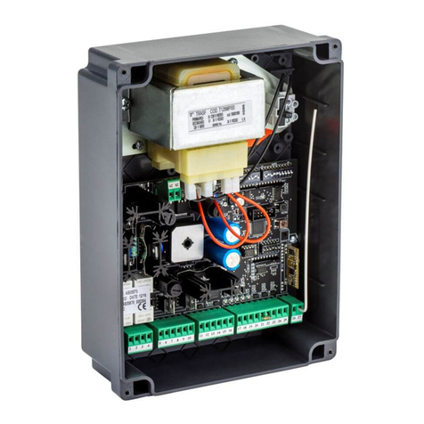
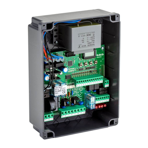
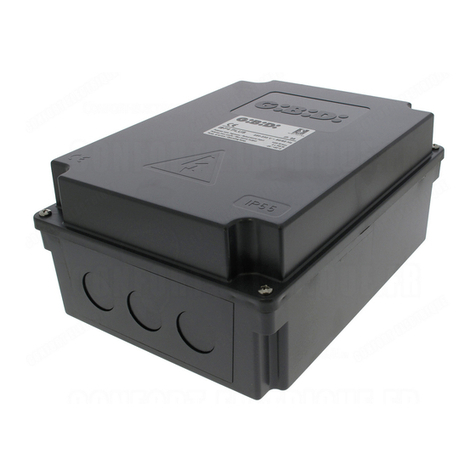
GiBiDi SR100 Guide

I UK
Centralina di controllo
ISTRUZIONI PER L’INSTALLAZIONE
Control unit
INSTRUCTIONS FOR INSTALLATIONS
SR100
SR100 - ( )AS05730

2SR100
UK
I
AVVERTENZE:
Questo prodotto è stato collaudato in GI.BI.DI. verificando la perfetta corrispondenza delle caratteristiche alle direttive
vigenti. GI.BI.DI. S.r.l. si riserva la facoltà di modificare i dati tecnici senza avviso, in funzione dell’evoluzione del prodotto.
LEGGERE ATTENTAMENTE QUESTO MANUALE PRIMA DI PROCEDERE ALL’INSTALLAZIONE.
SMALTIMENTO: GI.BI.DI. consiglia di riciclare i componenti in plastica e di smaltire in appositi centri
abilitati i componenti elettronici evitando di contaminare l'ambiente con sostanze inquinanti.
WARNINGS:
This product has been tested by GI.BI.DI. for full compliance with the requirements of the directives in force. GI.BI.DI.
S.r.l. reserves the right to change the technical data without prior notice in relation to product development.
CAREFULLY READ THESE INSTRUCTIONS BEFORE PROCEEDING WITH INSTALLATION.
DISPOSAL: GI.BI.DI. advises recycling the plastic components and to dispose of them at special
authorised centres for electronic components thus protecting the environment from polluting
substances.

3
SR100
I
1
2
17 18
GND
ANT
10 11 12 13 14 15 16
RX
027G2
F1
T1
F2
RL1 RL2
DIP1
DIP2
DL5
DL8
LEARN
DL1
DL2
DL3
DL6
5 6 7 8 9
1 2 3 4
M1 M2 M3 M4
A C B
EARTH
NEUTRAL
230 Vac
PHASE
230 Vac
230Vac 40W MAX
LAMP
LAMP
MOTOR
OPEN
MOTOR
CLOSE
MOTOR
COM
M
PHOTO
COM
G_OP
+24Vdc
EARTH
G_CL
START
SW12
SW11
A C B
SAF

4
I
Tipo
Apparecchiatura
Alimentazione
N° motori
Alimentazione motore
Tempo lavoro
Lampeggiante
Tempo pausa
Alimentazione accessori
Ricevitore radio
Temperatura di utilizzo
Apparecchiatura elettronica per l'automazione
di un motore per serrande
230Vac monofase 50/60 Hz
1
230 Vac
125 s max
230Vac 25W max
125 s max
24Vdc 1,2W max
433,92 Mhz A bordo
-20°C +60°C
SR100 / AS05730
• LED rosso di segnalazione contatto n.c. (photo).
• LED verdi di segnalazione contatti n.a. (start, generale_apre, generale_chiude).
• LED giallo di segnalazione emergenze - apprendimento tempi.
• LED rosso di segnalazione apprendimento codici radio
• Pulsante LEARN per memorizzazione codici radio
• Possibilità di usare l'ingresso SAF come finecorsa.
• Apprendimento tempi automatico.
CARATTERISTICHE TECNICHE / FUNZIONI
AVVERTENZE PER L'INSTALLAZIONE
• Prima di procedere con l'installazione bisogna predisporre a monte dell'impianto un interruttore magneto
termico o differenziale con portata massima 10A. L'interruttore deve garantire una separazione omnipolare dei
contatti, con distanza di apertura di almeno 3 mm.
• Per evitare possibili interferenze, differenziare e tenere sempre separati i cavi di potenza (sezione minima 1 , 5
mm²) dai cavi di segnale (sezione minima 0,5 mm²).
• Eseguire i collegamenti facendo riferimento alle tabelle seguenti e alla serigrafia allegata. Fare molta
attenzione a collegare in serie tutti i dispositivi che vanno collegati allo stesso ingresso N.C. (normalmente
chiuso) e in parallelo tutti i dispositivi che condividono lo stesso ingresso N.A. (normalmente aperto). Una
errata installazione o un uso errato del prodotto può compromettere la sicurezza dell'impianto.
• Tutti i materiali presenti nell'imballo non devono essere lasciati alla portata dei bambini in quanto potenziali
fonti di pericolo.
• Il costruttore declina ogni responsabilità ai fini del corretto funzionamento dell'automazione nel caso non
vengano utilizzati i componenti e gli accessori di propria produzione e idonei per l'applicazione prevista.
• Al termine dell'istallazione verificare sempre con attenzione il corretto funzionamento dell'impianto e dei
dispositivi utilizzati.
• Questo manuale d'istruzioni si rivolge a persone abilitate all'installazione di “apparecchi sotto tensione”
pertanto si richiede una buona conoscenza della tecnica, esercitata come professione e nel rispetto delle
norme vigenti.
• La manutenzione deve essere eseguita da personale qualificato.
• Prima di eseguire qualsiasi operazione di pulizia o di manutenzione , scollegare l'apparecchiatura dalle rete di
alimentazione elettrica.
SR100

5
I
Morsetto
M1
Posizione Segnale
1
3
N
EARTH
2
4
L
EARTH
Descrizione
Neutro alimentazione 230 Vac
Collegamento terra
Fase alimentazione 230 Vac
Collegamento terra
COLLEGAMENTI ELETTRICI: MORSETTIERE
Uscita lampeggiatore 230Vac 25W
Collegamento motore (apertura)
Uscita lampeggiatore 230Vac 25W
Comune motore
Collegamento motore (chiusura)
M2
5
7
LAMP
OPEN
6
8
9
LAMP
COM
CLOSE
Uscita fissa da utilizzare per
lampeggiatore con circuito di
lampeggio
Alimentazione 24 Vdc accessori esterni
Alimentazione accessori esterni. Comune Ingressi – Uscite
Ingresso GENERALE APRE (N.A.)
Ingresso GENERALE_CHIUDE (N.A.)
Ingresso START (N.A.)
Ingresso FOTOCELLULA (N.C.). Attivo solo in chiusura.
Ingresso DISPOSITIVI DI SICUREZZA. Vedere DIP 9-10.
M3
10 24VDC
11 GND
12
13
14
15
16
G_OP
G_CL
START
PHOTO
SAF
Ingresso SEGNALE ANTENNA
Connettore per il collegamento al programmatore PRG_01
Ingresso CALZA ANTENNA
M4
J3
17 + ANT
18 - ANT
In caso di guasto o anomalie di funzionamento staccare l'alimentazione a monte dell'apparecchiatura e chiamare
l'assistenza tecnica. Verificare periodicamente il funzionamento delle sicurezze. Le eventuali riparazioni devono
essere eseguite da personale specializzato usando materiali originali e certificati.
Il prodotto non deve essere usato da bambini o persone con ridotte capacità fisiche, sensoriali o mentali, oppure
mancanti di esperienza e conoscenza, a meno che non siano stati correttamente istruiti. Non accedere alla scheda
per regolazioni e/o manutenzioni.
AVVERTENZE PER L’UTENTE
ATTENZIONE: IMPORTANTI ISTRUZIONI DI SICUREZZA.
E' importante per la sicurezza delle persone seguire queste istruzioni.
Conservare il presente libretto di istruzioni
• L'apparecchiatura qui descritta deve essere utilizzata solo all'uso per il quale è stata concepita.
• L' utilizzo dei prodotti e la loro destinazione ad usi diversi da quelli previsti, non è stata sperimentata dal
costruttore, pertanto i lavori eseguiti sono sotto la completa responsabilità dell'installatore.
• Segnalare l'automazione con targhe di avvertenza che devono essere visibili.
• Avvisare l'utente che bambini o animali non devono giocare o sostare nei pressi del cancello.
• Proteggere adeguatamente i punti di pericolo (per esempio mediante l'uso di una costa sensibile).
SR100

6
I
SR100
Posizione Valore Tipo
500 mA RAPIDO
5 A
F1
F2 RAPIDO
Descrizione
Protezione uscita alimentazione accessori
Protezione scheda su ingresso alimentazione 230 Vac
FUSIBILI DI PROTEZIONE
DIP
Funzione Descrizione
Stato
DIP 1
ON
OFF
OFF
OFF
ON
OFF
ON
ON
OFF
ININFL.
ON
OFF
ON
ON
OFF
ON
ON
OFF
DIP 2
DIP 3
DIP 2
DIP 3
DIP 2
DIP 3
DIP 5
DIP 8
DIP 5
DIP 8
DIP 5
DIP 8
DIP 2
DIP 3
DIP 4
APPRENDIMENTO
TEMPI
PASSO - PASSO
STOP STOP
PASSO - PASSO
NON ATTIVO
GESTIONE
INGRESSI RADIO
CONDOMINIALE
GESTIONE COMANDI
ESTERNI
Abilita la procedura di apprendimento tempi
Funzionamento normale
I impulso di Start : APRE
II impulso di Start: ARRESTA (non richiuderà in automatico)
III impulso di Start : CHIUDE
IV impulso di Start : ARRESTA
I impulso di Start : APRE
II impulso di Start : CHIUDE
III impulso di Start : APRE
Canale 1 trasmettitore: apre
Canale 3 trasmettitore: chiude
Canale 2 e 4 trasmettitore: blocca il moto
La centrale riconosce un solo ingresso radio impostato con i DIP 6 e 7
La centrale riconosce un solo ingresso radio impostato con i DIP 6 e 7 ma:
la pressione continua per 3 s del canale 1 del trasmettitore comanda l'apertura di
TUTTE le centrali su cui è memorizzato il trasmettitore;
la pressione continua per 3 s del canale 3 del trasmettitore comanda la chiusura di
TUTTE le centrali su cui è memorizzato il trasmettitore.
In apertura non riceve altri comandi di Start dopo il primo, in pausa successivi
comandi di Start ricaricano il tempo di pausa.
I impulso di Start: APRE
Successivi impulsi di Start: Ininfluenti
Pausa da FCA o fine tempo di apertura.
Impulso di Start durante la pausa: ricarica il tempo pausa (se chiusura automatica
attiva)
oppure CHIUDE (se chiusura automatica non
attiva)
Impulso di Start in chiusura: APRE
I pulsanti GENERALE_APRE e GENERALE_CHIUDE funzionano con logica a
UOMO PRESENTE.
Tenendo premuto il pulsante, per il primo secondo verrà bloccato il moto poi inizierà
la manovra.
Il pulsante GENERALE_APRE comanda solo l'apertura. Tenendo premuto il
pulsante, per il primo secondo verrà bloccato il moto poi inizierà la manovra.
Il pulsante GENERALE_CHIUDE comanda solo la chiusura. Tenendo premuto il
pulsante, per il primo secondo verrà bloccato il moto poi inizierà la manovra.
PROGRAMMAZIONE FUNZIONI (DIP SWITCH - DIP1)
Le impostazioni vengono memorizzate durante la fase di riposo (porta chiusa).

Configura l'ingresso SAF come COSTA 8K2 CON FINECORSA.
Funzionamento uguale al punto precedente con possibilità di lettura
dell'interruttore di finecorsa.
L'attivazione di questo interruttore, precedente all'attivazione della costa, viene
interpretata come finecorsa. In questo caso la centrale non verrà tenuta bloccata
per effetto dell'intervento della costa.
E' necessario che l'interruttore colleghi in parallelo alla resistenza 8K2 interna
della costa un altra di uguale valore. [ ]
3
Configura l'ingresso SAF come STOP con contatto NA.
In caso d'intervento:
a riposo (porta chiusa): la centrale non apre;
in apertura: blocca il moto e il successivo start comanderà la chiusura;
in pausa: non consente la chiusura e il successivo start comanderà la chiusura;
in chiusura: blocca il moto e il successivo start comanderà l'apertura.
Assicurarsi che il dip STOP NC sia in posizione OFF.
Configura l'ingresso SAF come COSTA 8K2 SENZA FINECORSA.
In caso di intervento:
a riposo (porta chiusa): la centrale non apre;
in apertura: arresto e inversione del moto per 2 s. Al successivo impulso di start il
moto riparte nel senso di liberazione dell'ostacolo;
in pausa: non consente la chiusura e il successivo start comanderà la chiusura;
in chiusura:arresto e inversione del moto per 2 s. Al successivo impulso di start il
moto riparte nel senso di liberazione dell'ostacolo.
7
I
SR100
DIP
Funzione Descrizione
Stato
OFF
OFF
OFF
OFF
OFF
ON
ON
OFF
OFF
ON
ON
ON
ON
OFF
ON
ON
DIP 6
DIP 7
DIP 9
DIP 10
DIP 9
DIP 10
DIP 9
DIP 10
DIP 6
DIP 7
DIP 9
DIP 10
DIP 6
DIP 7
DIP 6
DIP 7
IMPOSTAZIONE
CANALI RADIO
GESTIONE
INGRESSO SAFETY
Il canale 1 del trasmettitore funziona come START.
Configura l'ingresso SAF come STOP con contatto NC.
In caso d'intervento:
a riposo (porta chiusa): la centrale non apre;
in apertura: blocca il moto e il successivo start comanderà la chiusura;
in pausa: non consente la chiusura e il successivo start comanderà la chiusura;
in chiusura: blocca il moto e il successivo start comanderà l'apertura.
Il canale 2 del trasmettitore funziona come START.
Il canale 3 del trasmettitore funziona come START.
Il canale 4 del trasmettitore funziona come START.

I
8SR100
DIP1
DIP2 ON
ON
IMPOSTAZIONI DI DEFAULT
LED
Segnale Descrizione
Colore
Verde
Verde
Verde
Rosso
Rosso
Giallo
DL1
DL2
DL3
DL6
DL7
DL5
GENERALE APRE
GENERALE CHIUDE
START
FOTOCELLULA
MEMO
RADIO
SAFETY
Si accende quando viene chiuso il contatto
Si spegne quando si apre il contatto della fotocellula
Vedere “Procedura Apprendimento Tempi”
Vedere “Gestione radio a bordo”
Con l'ingresso SAF attivo si accende il LED. Rimane acceso per 2 s,
poi si spegne brevemente e quindi si riaccende.
LED DI SEGNALAZIONE
DIP
Funzione Descrizione
Stato
ON
ON
OFF
OFF
DIP1
DIP 2
FOTOCELLULA
STOP NC
Disabilita l'ingresso PHOTO
Disabilita l'ingresso SAF configurato come STOP con contatto NC
Ingresso PHOTO abilitato
Abilita l'ingresso SAF configurato come STOP con contatto NC.
Abilita la lettura della costa 8K2
PROGRAMMAZIONE FUNZIONI (DIP SWITCH DIP2)
Le impostazioni vengono memorizzate durante la fase di riposo (porta chiusa).
IMPOSTAZIONI DI DEFAULT
DIP 1 ÷ 10 tutti OFF
8K2
8K2
RESISTENZA SUPPLEMENTARE
RESISTENZA INTERNA DELLA COSTA
COSTA
COLLEGAMENTO VERSO
LA CENTRALE SR100
INTERRUTTORE DI FINECORSA
ASSEMBLATO IN PROSSIMITÀ
DELLA CHIUSURA
Se la resistenza esterna da 8K2 risulta sempre essere in parallelo alla costa, l'intervento della stessa verrà sempre
interpretato come finecorsa
93

I
9
SR100
GESTIONE RADIO A BORDO
CARATTERISTICHE
Ricevitore radio 433,92 MHz
Codici memorizzabili max 200
APPRENDIMENTO CODICI
Premere il pulsante LEARN, si accende ilLED DL8 (rimane acceso 6 s dopo di che si spegne).
Premere il tasto selezionato con i dip n° 6 – 7 del trasmettitore da memorizzare ed il ricevitore dà un comando di start
alla centrale. Senza premere nuovamente il tasto LEARN è possibile apprendere ulteriori telecomandi della stessa
famiglia uno di seguito all'altro fino a che il LED DL8 rimane acceso. Dopo l'apprendimento dell'ultimo telecomando
bisogna attendere lo spegnimento del LED (circa 6 s) ad indicare che il sistema è uscito dall'apprendimento codici ed
è pronto per funzionare in modo normale.
Senza premere il pulsante LEARN è possibile memorizzare telecomandi semplicemente premendo
contemporaneamente per circa 6 s i tasti 1 e 2 di un telecomando già memorizzato sulla centrale. In questo modo si
pone il ricevitore in modalità apprendimento codici, dopodichè entro 6 s bisogna schiacciare un tasto qualsiasi del
trasmettitore nuovo da memorizzare.
CANCELLAZIONE DELLA MEMORIA
In caso di errore o quando si deve fare la cancellazione totale dei codici occorre premere il pulsante LEARN (il LED
rosso si accende ) e mantenerlo premuto fino a quando il LED si spegne nuovamente.
JUMPER DI CONFIGURAZIONE
SW11
SW12
Configurazione
Configurazione
Modalità di
funzionamento
Modalità di
funzionamento
Descrizione
Descrizione
APERTO
APERTO
C - B
A - C
A - C
HCS ROLLING
NORMALE
HCS FIX
DIP SWITCH
AUA
Funzionamento rolling code standard
Funzionamento standard
Funzionamento rolling code a codice fisso gestibile con Consolle PRG_01
Funzionamento a codice fisso con dip switch
Un telecomando configurato per mezzo del programmatore PRG_01 uguale ad un
altro verrà automaticamente memorizzato in caso di trasmissione continua per 5 s
(HCS ROLLING)

I
10 SR100
PROCEDURA DI APPRENDIMENTO TEMPI
1. Con porta a riposo (chiusa) porre il DIP n°1 (DIP SWITCH DIP1) in ON. Il LED giallo DL5 lampeggia velocemente.
Se in questa fase si rimette il DIP n°1 in OFF si esce dalla procedura, restano in memoria i dati salvati in
precedenza e il successivo impulso di START comanderà l'apertura.
2. START → Il motore si muove in apertura. Il LED giallo DL5 continua a lampeggiare velocemente. Il DIP
n° 1 diventa ininfluente.
3. START → Il motore si ferma in apertura e il LED giallo DL5 si accende fisso. La centrale rimane in attesa
di comandi.
Se in questa fase si pone il DIP n°1 in OFF si esce dalla procedura salvando solo il tempo di lavoro e disattivando la
chiusura automatica. Il LED giallo DL5 si spegne e il successivo impulso di START comanderà la chiusura.
4. START →Inizia il conteggio del tempo di pausa. Il LED giallo DL5 lampeggia lentamente.
Se in questa fase si pone il DIP n°1 in OFF si esce dalla procedura salvando solo il tempo di lavoro e disattivando la
chiusura automatica. Il LED giallo DL5 si spegne e il successivo impulso di START comanderà la chiusura.
5. START → Termina il conteggio del tempo di pausa, vengono memorizzati il tempo lavoro e il tempo
pausa. Il LED giallo DL4 rimane acceso fisso.
6. Per uscire dalla procedura di apprendimento tempi porre il DIP n° 1 in OFF e il successivo comando di START o
GENERALE_CHIUDE comanderà la chiusura
Per modificare i tempi memorizzati bisogna ripetere la procedura descritta.
ATTENZIONE
Durante la fase di apprendimento tempi non sono attivi gli ingressi PHOTO, SAF, GENERALE_APRE,
GENERALE_CHIUDE.
Se si utilizza il comando radio come START fare attenzione a configurare correttamente i dip n. 5 – 6 – 7 – 8.
VALORI CARICATI DI DEFAULT
Tempo lavoro: 30 s
Chiusura automatica disattivata

I
11
SR100
Dichiarazione di conformità UE
Il fabbricante:
GI.BI.DI. S.r.l.
Via Abetone Brennero, 177/B,
46025 Poggio Rusco (MN) ITALY
dichiara che il prodotto:
APPARECCHIATURA ELETTRONICA SR100
è conforme alle seguenti Direttive:
e che sono state applicate le seguenti norme:
Il Rappresentante Legale
Michele Prandi
Data 15/11/2021
Inoltre dichiara che il prodotto non deve essere utilizzato finché la macchina in cui
sarà incorporato non sia stata dichiarata conforme alla Direttiva 2006/42/CE.
Ÿ2014/35/UE
Ÿ2014/30/UE
Ÿ2014/53/UE
Ÿ2011/65/UE
ŸIEC 61000-6-1:2016 RVL
ŸIEC 61000-6-2:2016 RVL
ŸIEC 61000-6-3:2020
ŸIEC 60335-2-103:2015+AMD1:2017+AMD2:2019 CSV

12 SR100
UK
Type
Control unit
Electronic control unit for the automation
of a shutter motor
Power supply
N° motors
Motor power supply
Functioning time
Flashing light
Pause time
Accessories power supply
Radio receiver
Operating temperature
230Vac monophase 50/60 Hz
1
230 Vac
125 s max
230Vac 25W max
125 s max
24Vdc 1,2W max
433,92 Mhz on board
-20°C +60°C
• Red warning LED of n.c. contacts (photo).
• Green warning LEDs of n.o. contacts (start, general_open, general_close).
• Yellow warning LED for emergences - phases during time learning procedure
• Red warning LED of radio codes learning
• Key LEARN to memorize radio codes
• Possibility of using the SAF input as limit switch.
• Time self- learning.
TECHNICAL SPECIFICATIONS / FUNCTIONS
INSTALLATION WARNINGS
• Before proceeding with the installation, fit a magnetothermal or differential switch with a maximum capacity of
10A upstream of the system. The switch must guarantee omnipolar separation of the contacts, with an opening
distance of at least 3 mm.
• To prevent possible interference, differentiate and always keep the power cables (minimum cross-section
1,5mm²) separate from the signal cables (minimum cross-section 0,5mm²).
• Make the connections referring to the following tables and to the attached screen-print. Be extremely careful to
connect in series all the devices that must be connected to the same N.C. (normally closed) input, and in
parallel all the devices that share the same N.O. (normally open) input. Incorrect installation or improper use of
the product may compromise system safety.
• Keep all the materials contained in the packaging away from children, since they pose a potential risk.
• The manufacturer declines all responsibility for improper functioning of the automated device if the original
components and accessories suitable for the specific automation are not used.
• At the end of the installation, always check carefully the proper functioning of the system and the devices used.
• This instruction manual addresses people qualified for the installation of “live equipment”. Therefore, good
technical knowledge and professional practice in compliance with the regulations in force are required.
• Maintenance must be carried out by qualified personnel.
• Before carrying out any cleaning or maintenance operation, disconnect the control unit from the mains.
• This control unit may only be used for the purpose for which it was designed.
• Use of the product for purposes different from the intended use has not been tested by the manufacturer,
therefore any work is carried out on full responsibility of the installer.
SR100 / AS05730

13
SR100
UK
Terminal
M1
Position Signal
1
3
N
EARTH
2
4
L
EARTH
Description
Neutral power supply 230 Vac
Ground connection
Power supply phase 230 Vac
Ground connection
ELECTRICAL CONNECTIONS: TERMINALBOARDS
Flashing light output 230Vac 25W
Motor connection (opening)
Flashing light output 230Vac 25W
Common motor
Motor connection (closing)
M2
5
7
LAMP
OPEN
6
8
9
LAMP
COM
CLOSE
Fixed output to be used for
flashing light with flashing circuit
External accessories 24 Vdc power supply
External accessories power supply. Common Inputs – Outputs
Input GENERAL OPEN (N.O.)
Input GENERAL_CLOSE (N.O.)
Input START (N.O.)
Input PHOTOCELL (N.C.). Active only during closing.
Input SAFETY DEVICES. See DIP 9-10
M3
10 24VDC
11 GND
12
13
14
15
16
G_OP
G_CL
START
PHOTO
SAF
Input ANTENNA SIGNAL
Connector for connexion to the programmer PRG_01
Input ANTENNA BRAID
M4
J3
17 + ANT
18 - ANT
In the event of an operating fault or failure, cut the power upstream of the control unit and call Technical Service.
Periodically check functioning of the safety devices. Any repairs must be carried out by specialised personnel using
original and certified materials.
The product is not to be used by children or people with reduced physical, sensory or mental capabilities, or lack of
experience and knowledge, unless they have been given supervision or instruction. Do not intervene on the board for
regulations and/or maintenance.
WARNINGS FOR THE USER
WARNING: IMPORTANT SAFETY INSTRUCTIONS
For people's safety, it is important to follow these instructions.
Please keep this manual.
• Mark the automated gate with visible warning plates.
• Warn the user that children and animals may not play or stand around near the gate.
• Appropriately protect the dangerous points (for example, use a sensitive frame).

14 SR100
UK
Position Value Type
500 mA RAPIDO
5 A
F1
F2 RAPIDO
Description
Accessories power supply input protection
Board protection on 230 Vac power supply input
PROTECTION FUSES
OFF
OFF
ON
OFF
ON
ON
OFF
ININFL.
ON
OFF
ON
ON
OFF
ON
ON
OFF
DIP 2
DIP 3
DIP 2
DIP 3
DIP 2
DIP 3
DIP 5
DIP 8
DIP 5
DIP 8
DIP 5
DIP 8
DIP 2
DIP 3
DIP 4
STEP – STEP
STOP STOP
STEP - STEP
NOT ENABLED
RADIO INPUT
MANAGEMENT
CONDOMINIUM
EXTERNAL
COMMANDS
MANAGEMENT
DIP
Function Description
Status
DIP 1
ON
OFF
TIME
LEARNING
Enables the time learning procedure
Normal functioning
I Start pulse: OPENS
II Start pulse: STOPS (it will not close automatically)
III Start pulse: CLOSES
IV Start pulse: STOPS
I Start pulse: OPENS
II Start pulse: CLOSES
III Start pulse: OPENS
Channel 1 transmitter: opens
Channel 3 transmitter: closes
Channel 2 and 4 transmitter: stops the motion
The control unit recognizes only one radio input set with the DIP 6 and 7
The control unit recognizes only one radio input set with the DIP 6 and 7 but:
the continuous pressure for 3 s on the channel 1 of the transmitter manages the
opening of ALL the control units on which the transmitter is memorized;
the continuous pressure for 3 s on the channel 3 of the transmitter manages the
closing of ALL the control units on which the transmitter is memorized.
During opening, it does not receive other START commands after the first one, in
pause other START commands reload the pause time.
I Start pulse: OPENS
Next Start pulses: uninfluential
Pause from FCA or end of opening time
Start pulse during pause: reloads pause time (if automatic closing is enabled)
or CLOSES (if automatic closing is disabled)
Start pulse during closing: OPENS
The keys GENERAL_OPEN and GENERAL_CLOSE work with DEAD MAN logic.
Keeping the key pressed, the motion stops for one second and then the manoeuvre
starts.
The key GENERAL_OPEN manages only opening. Keeping the key pressed, the
motion stops for one second and then the manoeuvre starts.
The key GENERAL_CLOSE manages only the closing. Keeping the key pressed,
the motion stops for one second, then the manoeuvre starts.
FUNCTIONS PROGRAMMING ( DIP SWITCH DIP1)
The settings are memorized during the pause phase (door closed).

15
SR100
UK
DIP
Function Description
Status
OFF
OFF
OFF
OFF
OFF
ON
ON
OFF
OFF
ON
ON
ON
ON
OFF
ON
ON
DIP 6
DIP 7
DIP 9
DIP 10
DIP 9
DIP 10
DIP 9
DIP 10
DIP 6
DIP 7
DIP 9
DIP 10
DIP 6
DIP 7
DIP 6
DIP 7
RADIO CHANNELS
SETTING
SAFETY INPUT
MANAGEMENT
Channel 1 of the transmitter works as START.
It sets the SAF input as STOP with contact NC.
In case of intervention:
door closed: the control unit does not open;
in opening: it stops the motion and the next START will cause the closing;
in pause: it does not allow closing and the next start will cause the closing;
in closing: it stops the motion and the next start will cause the opening.
It sets the SAF input as STOP with contact NO.
In case of intervention:
Doro closed: the control unit does not open;
in opening: it stops the motion and the next start will cause the closing;
in pause: it does not allow closing and the next start will cause closing;
in closing: it stops the motion and the next start will cause the opening.
Please make sure that the dip STOP NC is on OFF.
It sets the SAF input as 8K2 EDGE WITHOUT LIMIT SWITCHES.
In case of intervention:
door closed: the control unit does not open;
in opening: stop and motion inversion for 2 s. at next start pulse the motion starts in
the obstacle-freeing direction;
in pause: it does not allow closing and the next start will cause closing;
in closing: stop and motion inversion for 2 s. At next start pulse the motion restarts
in the obstacle-freeing direction.
It sets the SAF input as 8K2 EDGE WITH LIMIT SWITCHES.
The functioning is the same as the previous point, but with possibility of reading the
limit switches switch
The enabling of this switch before the edge activation is recognized as limit switch.
In this case, the control unit is not blocked because of the edge intervention.
It is necessary that the switch connects in parallel to the 8K2 internal resistor of the
edge another one having the same value. [ ]
3
Channel 2 of the transmitter works as START.
Channel 3 of the transmitter works as START.
Channel 4 of the transmitter works as START.

DEFAULT SETTINGS
If the 8K2 external resistor is always in parallel to the edge, the intervention of the same edge is recognized as limit
switch.
DIP 1 ÷ 10 all OFF
93
16
UK
SR100
8K2
ADDITIONAL 8K2 RESISTANCE
EDGE INTERNAL RESISTANCE
SENSITIVE EDGE
CONNECTION TO THE
SR100 CONTROL UNIT
LIMIT SWITCH ASEMBLED
NEAR THE CLOSING
DIP
Function Description
Status
ON
ON
OFF
OFF
DIP1
DIP1
DIP2 ON
ON
DIP 2
PHOTOCELL
STOP NC
Disables PHOTO input
Disables SAF input set as STOP with NC contact
PHOTO input enabled
Enables SAF input set as STOP with NC contact.
Enables 8K2 edge reading
DEFAULT SETTINGS
SIGNALLING LEDS
FUNCTIONS SETTING ( DIP SWITCH DIP2)
Settings are memorized when the door is closed.
LED
Signal Description
Colour
Green
Green
Green
Red
Red
Yellow
DL1
DL2
DL3
DL6
DL7
DL5
GENERAL OPEN
GENERAL CLOSE
START
PHOTOCELL
MEMO
RADIO
SAFETY
It switches on when the contact is closed
It switches off when the photocell contact opens
See “Times learning procedure”
See “On board radio management”
The LED switches on with the SAF input enabled. It remains on for 2 s, then it
switches off and, after a few seconds, on again.

17
UK
SR100
ON BOARD RADIO MANAGEMENT
SPECIFICATIONS
Radio receiver 433,92 MHz
Memorizable codes max 200
CODES LEARNING
Press the LEARN key, the DL8 LED switches on (it remains on for 6 s, then it switches off).
Press the key selected with the dip n° 6 – 7 of the transmitter that has to be set, and the receiver gives a start
command to the control unit. Without pressing again the LEARN key, it is possible to memorize other transmitters of
the same kind one after the other until the DL8 LED remains on. After the learning of the last transmitter, wait until the
LED switches off (about 6 s) to indicate that the system has left the learning procedure and is now ready for the
standard work.
Without pressing the LEARN key, it is possible to memorize the transmitters just by pressing simultaneously the keys
1 and 2 of a transmitter already memorized on the control unit for about 6 s. In this way, the transmitter enters the code
learning mode; it is now necessary only to press any of the keys of the new transmitter that has to be memorized.
MEMORY DELETION
In case of mistake, or when the complete deletion of all codes is necessary, press the LEARN key (the red LED
switches on) and keep it pressed until the LED switches off.
CONFIGURATION JUMPER
SW11
SW12
Configuration
Configuration
Functioning
mode
Functioning
mode
Description
Description
OPEN
OPEN
C - B
A - C
A - C
HCS ROLLING
NORMAL
HCS FIX
DIP SWITCH
AUA
Standard rolling code functioning with variable code
Standard functioning
Rolling code functioning with fixed code manageable with PRG_01 Consolle
Fixed code functioning with dip switch
A transmitter set by means of the PRG_01 programmer as another one is
automatically memorized in the event of continuous transmission for 5 s (HCS
ROLLING)

18
UK
SR100
TIMES LEARNING PROCEDURE
1. When the door is closet, place the DIP n°1 (DIP SWITCH DIP1) on ON. The yellow LED DL5 flashes fast.
In this phase, if the DIP n°1 is put on OFF you leave the procedure, the memorized data remain stored and the
next START command will cause the opening.
2. START →The motor moves in opening. The yellow LED DL5 keeps on flashing fast. The DIP n° 1
becomes uninfluential.
3. START →The motor stops in opening and the yellow LED DL5 switches on fixed. The control unit waits
for commands.
If in this phase the DIP n°1 is put on OFF, you leave the procedure, only saving the work time and disabling the
automatic closing. The yellow LED DL5 switches off and the next START command will cause the closing.
4. START →The pause time counting starts. The yellow LED DL5 flashes slowly.
In this phase, if the DIP n°1 is put on OFF, you leave the procedure, only saving the work time and disabling the
automatic closing. The yellow LED DL5 switches off and the next START command will cause the closing.
5. START →It ends the pause time counting, the work time and the pause time are memorized. The yellow
LED DL5 remains on fixed.
6. To leave the times learning procedure, put the DIP n° 1 on OFF and the next START command or
GENERAL_CLOSE will cause the closing.
To modify the memorized times, it is necessary to repeat the above procedure.
WARNING
During the times learning phase, the PHOTO, SAF, GENERAL_OPEN, GENERAL_CLOSE are disabled.
If the radio command is used as START, pay attention to the correct configuration of the dip n. 5 – 6 – 7 – 8.
DEFAULT VALUES
Work time: 30 s
Automatic closing disabled.

19
UK
SR100
Date 15/11/2021
UKCA Declaration of conformity
The manufacturer:
GI.BI.DI. S.r.l.
Via Abetone Brennero, 177/B,
46025 Poggio Rusco (MN) ITALY
Declares that the product:
ELECTRONIC CONTROL UNIT SR100
Are in conformity with the essential requirements and other relevant requirement of:
and that the following harmonised standards have been applied:
The legal Representative
Michele Prandi
Restriction of the Use of Certain Hazardous Substances
in Electrical and Electronic Equipment Regulations 2012;
Electrical Equipment (Safety) Regulations 2016;
Radio Equipment Regulations 2017;
ŸEN 61000-6-1
ŸEN 61000-6-2
UE Declaration of conformity
The manufactuerer:
GI.BI.DI. S.r.l.
Via Abetone Brennero, 177/B,
46025 Poggio Rusco (MN) ITALY
Declares that the product:
ELECTRONIC CONTROL UNIT SR100
are in conformity with the following directives:
and that the following harmonized standards have been applied:
Il Rappresentante Legale
Michele Prandi
Data 15/11/2021
Ÿ2014/35/UE
Ÿ2014/30/UE
ŸIEC 61000-6-1:2016 RVL
ŸIEC 61000-6-2:2016 RVL
ŸEN 61000-6-3
ŸEN 60335-1
Ÿ2014/53/UE
Ÿ2011/65/UE
ŸIEC 61000-6-3:2020
ŸIEC 60335-2-103:2015+AMD1:2017+AMD2:2019 CSV

GI.BI.DI. S.r.l.
46025 Poggio Rusco (MN) - ITALY
Tel. +39.0386.52.20.11
Fax +39.0386.52.20.31
E-mail: [email protected]
Numero Verde: 800.290156
Via Abetone Brennero, 177/B
w w w . g i b i d i . c o m
Cod. AIC8602 - 06/2022 - Rev. 02
This manual suits for next models
1
Table of contents
Languages:
Other GiBiDi Control Unit manuals
Popular Control Unit manuals by other brands

Warn Industries
Warn Industries 89960 installation guide

aevit
aevit VIC 2.0 Installation & operation manual

MX
MX Atmos Select 3 Way Fitting instructions

Life
Life RG1 DL Instructions and warnings for installation, use and maintenance

Environ
Environ ENVIRONCONNECTEDModule installation instructions

V2
V2 CITY11 manual