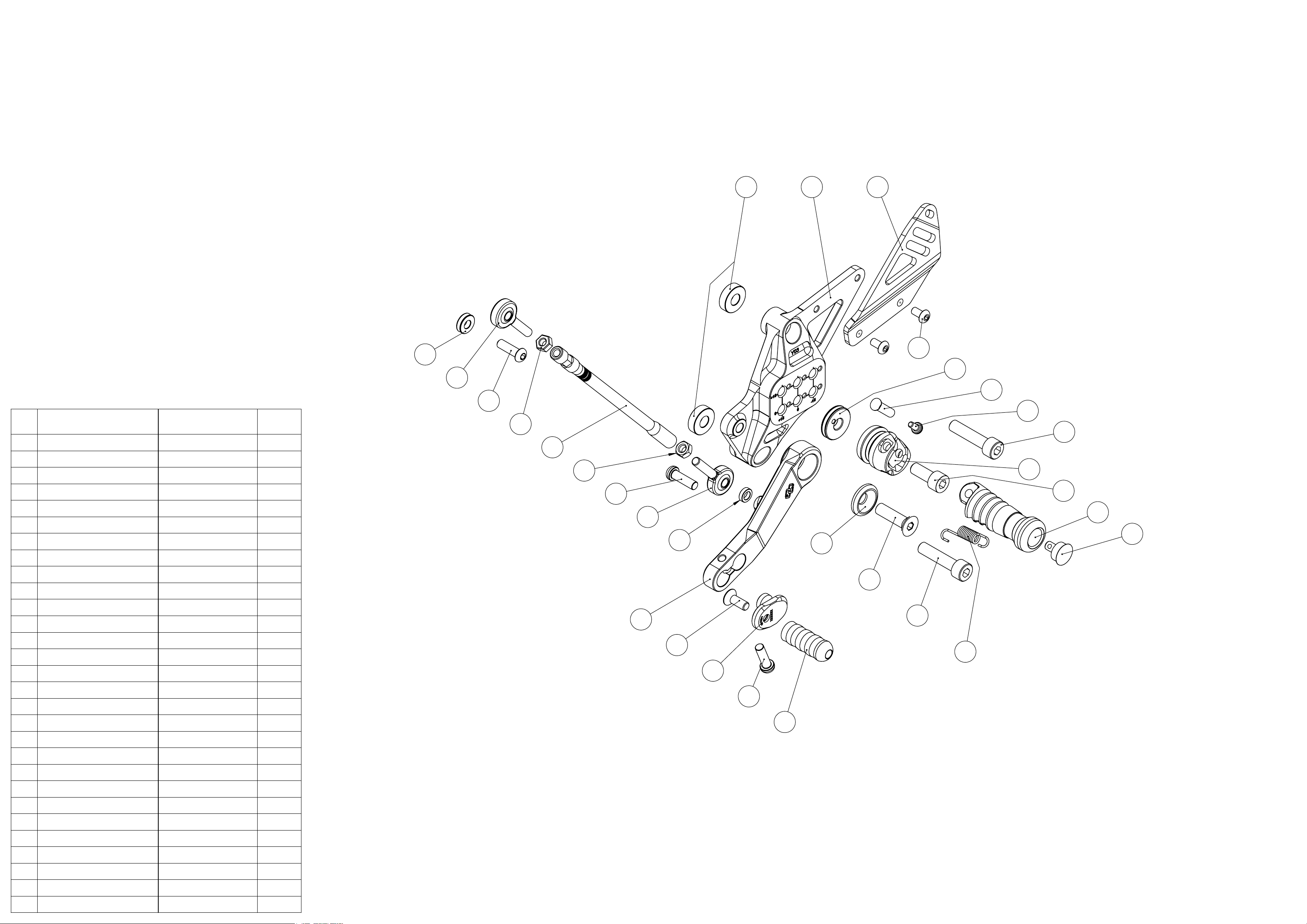
manuals.online logo
Brands
  1. Home
  2. •
  3. Brands
  4. •
  5. gilles.tooling
  6. •
  7. Motorcycle Accessories
  8. •
  9. gilles.tooling FXR-Y03 User manual

gilles.tooling FXR-Y03 User manual

Rev 03, 06/ 2018
FXR-Y03
fxr.rearsets
Anbauanleitung
Manual
FXR-Y03 rearset
Sicherheitshinweise
Allgemeine Hinweise
-Ein unsicher aufgestelltes Motorrad kann bei den folgenden Arbeiten umfallen! Achten Sie darauf, dass
das Fahrzeug sicher steht.
-Verbrennungsgefahr bei heissem Motor und Auspuff! Vor Beginn der Arbeit heiße Fahrzeugteile abkühlen
lassen.
-Kinder und Tiere aus dem Arbeitsbereich fernhalten.
-Schmuck (Uhr, Ringe, Ketten, etc) vor Arbeitsbeginn ablegen.Es besteht Unfallgefahr durch Hängenbleiben
oder elektrischen Kurzschluss.
-Die Montage und Funktion bezieht sich ausschliesslich auf Serienmotorräder.
-Wir übenehmen keine Gewährleistung für die Verwendung an Sonderumbauten und von
Sonderzubehörteilen.
-Nach Montage des Produkts durch eine Werkstatt, ist diese Anbauanleitung dem Kunden auszuhändigen.
-Bewahren Sie die Anbauanleitung sorgfältig auf, und geben Sie dieses Produkt nur mit dieser
Anbauanleitung an Dritte weiter.
-Sollte die erforderliche Anleitung nicht mehr in Ihrem Besitz sein, wenden Sie sich bitte an:
info@gillestooling.com
Montagehinweise
-Alle Schrauben und Muttern werden mit Drehmoment nach DIN/ISO festgezogen. Abweichende
Drehmomente werden angegeben.
-Lagerungen und Schraubverbindungen sind mit einem geeigneten Schmiermittel einzusetzten, um ein
Festfressen zu verhindern.
-Arbeiten und Entlüftung am Bremssystems sind nur von fachkundigem Personal durchzuführen.
-Es ist unbedingt darauf zu achten, dass keine Züge, Kabel oder Leitungen (insbesondere Bremsleitungen)
andere Fahrzeugkomponenten berühren oder daran scheuern.
-Nach jeder Montage sind alle Schrauben auf festen Sitz und das vorgeschriebene Drehmoment zu
überprüfen.
-Es ist unbedingt darauf zu achten, dass alle Teile immer einen Mindesabstand von 5mm zu beweglichen
Fahrzeugteilen haben.
Diese Anbauanleitung ist sorgfältig und vollständig vor Beginn der
Einbauarbeiten durchzulesen.
Wir bedanken uns für den Erwerb eines unserer Produkte und wünschen Ihnen viel Spaß. Machen
Sie aus einem Serienfahrzeug Ihre individuelle Maschine.
-Sicherheit ist oberstes Gebot.
-Haben Sie das erforderliche Werkzeug und genügend Mechanikerwissen und praktische Erfahrung?
-Unsere Produkte dürfen nur von fachkundigem Personal montiert werden.
-Nichtbeachtung der Anweisung kann zu Beschädigungen des Fahrzeuges, des Produktes bzw. zur
Gefährdung des Fahrers führen.
-Für Schäden, die aufgrund von Nichtbeachtung unserer Anweisungen entstanden sind, können wir keine
Haftung oder Gewährleistung übernehmen.
Betriebserlaubnis
-Beachten Sie die für Ihr Land geltenden Zulassungsbestimmungen.
-Für den Bereich der Bundesrepublik Deutschland gilt:
Ein Eintrag in die Fahrzeugpapiere ist erforderlich!
FXR-Y03 rearset
safety instructions
You must read these installation instructions carefully and make sure you
understand everything they contain, before commencing work.
Thank you for purchasing one of our products and we wish a lot of enjoyable riding. With Gilles you
make a standard bike - your bike.
-Safety always comes first.
-Do you have the correct tools?
-Do you have the ability and aptitude to confidently mount thes product. If in doubt consult a skilled
technican.
-We always advise fitment is carried out by skilled personal.
-Non-compliance with the instructions can be hazardous. For your own protection and the safety of the bike
please always follow the instructions.
-Any Gilles parts will not be covered by warranty it fitted incorrectly.
General instructions
-Please ensure the motorcycle is adequately secured before commencing work.
-Always make sure that the motorcycle is stable and firmly supported.
-A hot engine and exhaust system can burn. Allow all hot parts to cool before commencing work.
-Keep children and household pets well away from the work zone.
-Remove all items of personal jewellry (rings, chains,wristwatch, etc.) before commencing work.
-The fitment instructions relate only to the fitment on a standart motorcycles.
-We cannot warranty or legislate for interaction or interference with non standard or custom parts.
-If a technican is installing the parts please ensure these instructions are passed to the owner.
-Please keep the instruction manual at a safe place. In case of selling our product, please hand the
installation instructions over to the new owner.
-Consult [email protected] if the instructions are no longer in your possession.
Operating licence
-Always comply with the regulations regarding approval in the country of use.
-For the Federal Republic of Germany:
A entry in the vehicle´s registration papers is required!
Assembling note
-Screws, bolts and nuts are tightened in accordance with the applicable DIN/ISO standards. Tightening
torques that deviate from the standards are stated.
-All threaded connections and bearings must be greased with suitable grease. Please be careful with the
tools to avoid i.e. scratches.
-Mounting and bleeding at the brake system only by skilled personal.
-Take care that no wires and hoses (especially brake hoses) are too close or touching other components or
moving parts.
-After each mounting check all bolts for correct tightening and specified torque moment.
-Take care that any parts always have a minimum clearence of 5 mm to any moving parts.
6
26
25
15
2
16
1
14
22
24
27
19
5
3428713
9
8
12
23
29
10
11
25
17
28
20
21
18
pos
article no.
description
qty.
[pcs.]
1
FXR-GR-Y03-*
right base plate
1
2
FXR-BU-10-*
holder brake unit
1
3
HA-UL-MT07-*
holder ball bearing
1
4
UB-31-*
brake lever
1
5
UL-13-R-*
brake lever bearing
1
6
CAR03-R 8.5-49-01-*
heel protector
1
7
UEX-01-*
excenter
1
8
UF-ST-01-*
plug
1
9
UF-24-*
footrest
1
10
RG-810-*
footrest joint
1
11
RG-BO-01
bolt RG
1
12
SIF-19078
pull spring
1
13
UTR01-*
brake lever toe piece
1
14
UAD03-30
brake cylinder adapter
1
15
DS 20-8-6-*
distance
1
16
DS-20-8-12-*
distance
1
17
DS24-8.2-5-*
distance
1
18
BR-05
brake bolt
1
19
RZ-115NI
pull spring
1
20
FE60
pull spring
1
21
FE70
pull spring
1
22
M8x35-912-VA
cylinder bolt
2
23
M8x20-912-VA
cylinder bolt
1
24
M8x30-7991-VA
countersunk bolt
1
25
M6x16-7991-VA-PRE10-1
countersunk bolt
2
26
M8x25-7380-VA
oval-head bolt
2
27
M8x12-7380-VA
oval-head bolt
2
28
M6x20-7380-VA-TX-PRE10-1
oval-head bolt
2
29
M4x8-14583-VA-TX
oval-head bolt
1
30
698ZZ
bearing
2
1 3
25
13
6
4
12
5
8
21
19
10
9
22
2
16
27
18
14
11
17
15
28
23
19
20
26
7
24
24
pos
article no.
description
qty.
[pcs.]
1
FXR-GL-Y03-*
left basic plate
1
2
US-47-*
gear lever
1
3
CAR03-L 5,5-40-*
left heel protector
1
4
RG-810-*
footrest joint
1
5
UF-24-*
footrest
1
6
RG-BO-01
bolt RG
1
7
SIF-19078
pull spring
1
8
UF-ST-01-*
plug
1
9
UEX-01-*
excenter
1
10
UTR-15-*
gear lever toe piece
1
11
USW09-*
gear shaft
1
12
BL01-*
cover
1
13
DS24-8.2-5-*
distance
1
14
DS 20-8-6-*
distance
2
15
DS-14-6-4
distance
1
16
DS-10-6-3
distance
1
17
M6-934-L-VA
nut lh
1
18
M6-934-VA
nut 1
19
M8x35-912-VA
cylinder bolt
2
20
M8x20-912-VA
cylinder bolt
1
21
M8x30-7991-VA
countersunk bolt
1
22
M6x16-7991-VA-PRE10-1
countersunk bolt
1
23
M6x20-7380-VA-PRE10-1
oval-head bolt
1
24
M6x20-7380-VA-TX-PRE10-1
oval-head bolt
2
25
M5x10-7380-VA
oval-head bolt
2
26
M4x8-14583-VA-TX
oval-head bolt
1
27
GAKFR6
ball and socket bearing
1
28
GAKFL6
ball and socket bearing
1
29
698ZZ
bearing
2
B: Hängen Sie die Feder FE60 (mm) (2014- 2017, RM04) oder FE70 (mm) (2017< X, RM17/ RM18) wie in
der Abbildung gezeigt in den Bremshebel. Achten Sie auf die Richtung beim einhängen!
B: Insert the hook of the spring FE60 (mm) (2014- 2017, RM04) or FE70 (mm) (2017< X, RM17/ RM18)
like shown in the picture into the brake lever. Be sure to insert the spring from the right direction!
B
FE60 (mm) = 2014- 2017, RM04
oder / or
FE70 (mm) = 2017< X, RM17/ RM18
FE60 (mm)
oder / or
FE70 (mm)
FXR-Y03 rearset
Anbauanleitung/ Manual
-ES WIRD EMPFOHLEN DIE ANLAGE VON EINER FACHWERKSTATT INSTALLIEREN ZU LASSEN.
-INSTALLATION RECOMMENDED BY AN OFFICIAL DEALER / WORKSHOP.
A: Original Rastenanlage demontieren und Auspuff, sowie Schwinge durch Abdecken gegen
Beschädigungen schützen wie in Bild A dargestellt.
A: Detach original rearset like shown in picture A and use protective foil to cover the exhaust and swing
arm to avoid scratches.
A
Rechts/right side
Schutzfolie/
protective foil
FXR-Y03 rearset
Anbauanleitung/ Manual
C: Drehen Sie den Bremszylinderadapter UAD03-30 auf die Betätigungsstange des Bremszylinders.
Die originale, schwarze Kontermutter findet dabei Verwendung.
Stellen Sie den Adapter auf das Abstandsmaß 17,5mm ein als Grundlage für spätere Einstellungen.
D: Fetten Sie den Bremsbolzen BR-05 am Bremshebel. Normales, handelsübliches Industriefett.
C: Screw the brake cylinder adapter UAD03-30 onto the master cylinder`s actuating rod and use the
original, black counter nut.
Adjust the adapter to the distance of 17,5mm as basic set up for following adjustments.
D: Grease the brake bolt BR-05 with standard, industrial grease.
C D
UAD03-30
original!
Fett/ grease!
BR-05
: ~17,5mm
Abstand
distance
E
FXR-BU-10
E: Stecken Sie den BR-05 und somit die Anlage in den Adapter UAD-03-30. Klappen Sie die
Bremszylinder- Trägerplatte FXR-BU-10 in die Flucht der M8- Befestigungsgewinde des Bremszylinders
E: Put the brake bolt BR-05 into the adapter UAD-03-30. Align the master cylinder holding plate FXR-BU-
10 with the master cylinder`s M8- inner threads.
H I
H: Montieren Sie den Bremslichtschalter! Einhängen der Feder FE60 (mm) (2014- 2017, RM04) oder FE70
(mm) (2017< X, RM17/ RM18) in den Betätigungspin des Schalters.
I: Das Halteblech des Bremslichtschalters wird (wie dargestellt) zwischen Bremszylinder und dessen
Trägerplatte montiert.
H: Install the brake light switch! Connect the spring FE60 (mm) (2014- 2017, RM04) or FE70 (mm) (2017<
X, RM17/ RM18) to the actuating pin of the switch.
I: The holding bracket for the switch must be placed between (like shown in the picture) the master cylinder
and its holding plate.
FE60 (mm)
oder / or
FE70 (mm)
FXR-Y03 rearset
Anbauanleitung/ Manual
unten/ bottom
G
oben/ top
12
F: Das ausführen des Schrittes C hat dazu geführt, dass die Bohrungen der Bremszylinder- Halteplatte
FXR-BU-10 deckungsgleich mit den M8- Gewinden des Bremszylinders liegen- Beide in einer Flucht!
(Anderfalls ist der Adapter UAD-03-30 eine viertel oder halbe Umdrehung auf der Betätigungsstange rein-
oder rauszuschrauben)
G: Kontern Sie die Einstellung wie im Bild dargestellt. Anziehen mit Gefühl und ohne grobe Gewalt.
F: You should find the holes of the cylinder holding plate fall in line with the M8 inner threads of the master
cylinder (reason of doing step C)- Both in alignment!
(If not, turn the adapter UAD03-30 a quarter or half turning up or down onto the actuating rod to correct the
satus)
G: Fix the adjustment like shown in the picture. Smooth tightening without brute force.
F
K: Montieren Sie den Bremszylinderschutz CAR03-R 8.5-49 wie im Bild dargestellt. Die Schrauben
M8x25-7380 müssen sich dabei aufgrund vom Status in Schritt F leichtgängig einschrauben lassen!
Anzugsdrehmoment: 20 Nm
K: Mount the master cylinder- guard CAR03-R 8.5-49 like the picture shows. The bolts M8x25-7380
should screw in without high resistance, if aligned properly (compare step F).
Tightening torque: 20 Nm
20 Nm
5
K
CAR03-R 8.5-49
M8x25
-7380
FXR-Y03 rearset
Anbauanleitung/ Manual
20 Nm
6
J
J: Schrauben Sie die Rastenanlage gegen die Rahmenplatte des Fahrzeuges unter Nutzung der
ausgewiesenen Schrauben und Distanzscheiben. Ziehen Sie die beiden Schrauben M8x35-915 mit dem
angegebenen Anzugsdrehmoment fest!
Anzugsdrehmoment: 20 Nm
J: Mount the right side of the rearset on the motorcycle`s frame by using the displayed bolts and spacers.
Tighten the bolts M8x35-912 with the specified tightening torque.
Tightening torque: 20 Nm
DS 20-8-6-B
DS 20-8-12-B
M8x35
-912
FXR-Y03 rearset
Anbauanleitung/ Manual
L M
L: Überprüfen des Bremsspieles durch Drehen des Hinterrades und Betätigen der Bremse mit der Hand
(siehe Bild). Sollte das Bremsspiel durch die Einstellung nicht ausreichen (Bremsbeläge liegen
an/schleifen) oder zu groß sein (zu viel Leerweg bis Druckpunkt) kann durch nochmaliges rein- oder
rausdrehen der Betätigungsstange (zurück in Schritt C) korrigiert werden. Der Bremshebel muss ein
spürbares Spiel aufweisen bevor der Bremskolben betätigt wird!
M: Stellen Sie die Sensibilität beim Auslösen des Bremslichtes ein. Drehen Sie dabei an der Kunststoff-
Stellmutter des Schalters (am Sechskant). Mehrmalige Korrekturen sind möglich. (Testen Sie das
Auslösen des Bremslichtes durch Betätigen des Bremshebels!)
L: Test the brake freeplay by spinning the rear wheel and pressing the brake by hand (like shown in the
picture). If the brake clearance/ freeplay in is not enough (brake linings fit/grind) or too much (too much
lever travel until pressure point), you can turn the actuating rod in or out to adjust it (back in step C). The
brake lever must have noticable freeplay before the brake piston gets pressed!
M: Adjust the sensibility of the brake light. Adjust the brake light switch by turning the plastic nut of the
swith (turn the hexagon). Repeated corrections of this step are possible. (Test the function of the brake
light by pushing the brake lever!)
-Zur Durchführung des folgenden Tests sollte das Hinterrad frei drehbar in der Luft sein!
-For the following test the rear wheel should be able to spin free!
Funktionsprüfung
der Bremse !!!
Check the function
of the brake !!!
O
O: Drehen Sie die mitgelieferte Schaltwelle USW09 wie dargestellt komplett auf das Kugellkopfgelenk
des Schalthebels. (Kontermutter dabei bis Anschlag an das Kugelkopfgelenk und Welle bis Anschlag
gegen die genannte Mutter)
O: Turn the delivered gear shaft USW09 like shown in the picture completly onto the gear lever`s ball
joint. (Screw the counter nut tight against the ball joint and in the next step the gear shaft against the
nut)
USW09
FXR-Y03 rearset
Anbauanleitung/ Manual
Links/left side
N
N: Demontieren Sie die originale Rastenanlage, sowie den originalen Kugelgelenkkopf von dem
Schaltarm.
Der Schaltarm ist um einen Zahn im Uhrzeigersinn verdreht zu montieren (im Vergleich zur Original-,
Ausgangsstellung). Originalschraube mit dem Herstelleranzugsdrehmoment festzuziehen.
Anzugsdrehmoment: 14 Nm
N: Remove the original rearset system and the original ball joint from the gear arm.
Adjust the gear arm one tooth turned in clockwise direction (in comparison to the original-, starting
position). Tighten the original bolt with the manufacturer tightening torque.
Tightening torque: 14 Nm
14 Nm
5
Originalschraube/
original bolt
Q
DS 14-6-4
10 Nm
4
R
R: Montieren Sie die Schaltwelle an den Schaltarm unter Nutzung der ausgewiesenen Schraube und
Distanzscheibe. Ziehen Sie die Schrauben M6x20-7380 fest!
Anzugsdrehmoment: 10 Nm
R: Mount the gear shaft onto the gear arm by using the displayed bolt and spacer. Tighten the bolt M6x20-
7380 with the specified tightening torque!
Tightening torque: 10 Nm
M6x20-7380
FXR-Y03 rearset
Anbauanleitung/ Manual
M8x35-912
DS 20-8-6-B
P Q
P: Schrauben Sie die Rastenanlage gegen die Rahmenplatte des Fahrzeuges unter Nutzung der
ausgewiesenen Schrauben und Distanzscheiben. Ziehen Sie die beiden Schrauben M8x35-915 mit dem
angegebenen Anzugsdrehmoment fest!
Anzugsdrehmoment: 20 Nm
Q: Drehen Sie den Kugelgelenkkopf wie dargestellt bis zum Anschlag in die Schaltwelle USW09.
P: Mount the left side of the rearset on the frame by using the displayed bolts and spacers. Tighten the
bolts M8x35-912 with the specified tightening torque.
Tightening torque: 20 Nm
Q: Turn the ball joint until Stop into the gear shaft USW09 like shown in the picture.
20 Nm
6
FXR-Y03 rearset
Anbauanleitung/ Manual
S
: 8mm
Abstand
distance
auf Anschlag
until stop
T
T: Fixieren Sie die Einstellung der Schaltwelle und deren Kugelköpfe wie in den Bildern dargestellt!
(Maulschlüssel 8 zum gegenhalten an der Schlüsselfläche der Schaltwelle und Maulschlüssel 10 für die
Muttern)
T: Keep the gear shaft in place by countering the nuts like shown in the pictures! (Use a open-end wrench
size 8 to fix the gear shaft while you`re countering with an open-end wrench size 10)
10
8
10
S: Stellen Sie die Höhe des Schalthebels ein! Drehen Sie die Schaltwelle wie dargestellt bis auf das Maß
8mm (Maß zwischen Mutter und Schaltwelle)! Es ist untersagt den Hebel noch tiefer einzustellen
(Keine Maße größer als 8mm)!
Feinkorrekturen erfolgen später über den Exzenter am Trittstück!
S: Adjust the height of the gear lever by turning the gear shaft. You must not choose any lever height that
results in a distance bigger than 8mm between the edge of the shaft and the counter nut- The lever
position becomes to low if the distance is more than 8mm.
Fine adjusting is possible by turning the excentric toe piece!
FXR-Y03 rearset
Einstellungen/ Adjustments
1: Entfernen Sie die Fussrate um Ihre neue, individuelle Sitzposition auf der Fussrastenanlage einzustellen. Ablauf
auf rechter und linker Seite identisch (R=L)!
1: Remove the footpeg to adjust your new and individual ridingposition on the rearset system`s basic plate.
Procedure is on the right and left side the same (R=L)!
1.1 / 1.2: Entfernen Sie die Schraube (M4x8-14583) und den Bolzen (RG-BO-01) gemäß der Darstellungen.
1.1 / 1.2: Detach the screw screw (M4x8-14583) and the bolt (RG-BO-01) according to the pictures.
1.1
1.2
1.3
1.4
1.3: Ziehen Sie am Rastenkörper (a) und schwenken Sie diesen aus dem Gelenk (RG-810) heraus (b).
1.4: Demontieren Sie die Schraube M8x20-912und somit das Gelenk RG-810. Es folgt 2 Einstellvorgabe!
1.3: Pull at the footpeg (a) and slide it outside the joint (RG-810) according to the picture (b).
1.4: Disassemble the screw M8x20-912and thus the joint like the picture shows. It follows 2 Adjustment
specification!
b
a
RG-810
2
R=L
2 Einstellvorgabe: Fußraste darf nur nach oben und leicht nach hinten klappen (ca. 45 Winkelgrad).
2 Adjustment specification: The footrest may only fold upwards and slightly towards the rear (approx. 45 degrees).
FXR-Y03 rearset
Einstellungen/ Adjustments
4: Trittstückverstellung
-Zur Verstellung des Trittstückes ist die
Schraube M6x20-7380-TX zu entfernen oder
zu lösen.
-Die zweite Bohrung kann ebenfalls zur
Positionierung genutzt werden. (Schalt-, sowie
Bremsseite!)
-Trittstück drehbar einstellen und Schraube
festziehen.
Anzugsdrehmmente: 10 Nm
4: Toe piece adjustment
-Loosen or remove the bolt M6x20-7380-TX
to adjust the toe piece.
-The second hole can also be used and offers
more options to adjust.
(at the shift-, and brake side!)
-Turn the toe piece to desired position at the
excentric and re-tighten bolt.
Tightening torques: 10 Nm
R=L
4
3:-Schraube M8x20-912, Anzugsdrehmoment: 20Nm
-Schraube M4x8-14583, handfest
-Bolzenkopf nach OBEN!
3:-Screw M8x20-912, tightening torque: 20Nm
-Screw M4x8-14583, hand- tight
-bolt head UPWARDS!
3: Montieren Sie die Fussraste in umgekehrter Reihenfolge zur Demontage (Schritte 1.1 bis 1.4).
3: Install the footpeg in turned direction to the disassembling steps (step 1.1 till 1.4).
3
Bolzenkopf nach OBEN
bolt head UPWARDS
10 Nm
Pos. Description Part-No. Qty. OK
1 bolt M8x35-912-VA 4
M6x20-7380-VA
Precote 10-1
3 bolt M8x25-7380-VA 2
4 spacer DS-14-6-4 1
5 spacer DS-20-8-6-B 3
6 spacer DS-20-8-12-B 1
7adapter
UAD03-30 1
8 spring
FE60 1
9 spring
FE70 1
11 certificate ab: 144XT0020-04-KND 1
12 manual FXR-Y03-(GT)-ABA 1
MA
Datum
10
2
Rev 03, 06/ 2018
1
bolt
heel guard
CAR03-R 8,5-49-01-*
(gebogen)
1
FXR-Y03 rearset
Packzettel/ packing list

Other gilles.tooling Motorcycle Accessories manuals

gilles.tooling K08 User manual

gilles.tooling

gilles.tooling K08 User manual

gilles.tooling AS 31 GT User manual

gilles.tooling

gilles.tooling AS 31 GT User manual

gilles.tooling AS31GT User manual

gilles.tooling

gilles.tooling AS31GT User manual

gilles.tooling fxr.rearsets-H05 User manual

gilles.tooling

gilles.tooling fxr.rearsets-H05 User manual

gilles.tooling m2-MV01 User manual

gilles.tooling

gilles.tooling m2-MV01 User manual

gilles.tooling VCR38GT User manual

gilles.tooling

gilles.tooling VCR38GT User manual

gilles.tooling AS 31 GT Series User manual

gilles.tooling

gilles.tooling AS 31 GT Series User manual

gilles.tooling Rct10gt- BM08 User manual

gilles.tooling

gilles.tooling Rct10gt- BM08 User manual

gilles.tooling MUE2-D01 User manual

gilles.tooling

gilles.tooling MUE2-D01 User manual

gilles.tooling RCT10GT-K02 User manual

gilles.tooling

gilles.tooling RCT10GT-K02 User manual

gilles.tooling MPCL-02 User manual

gilles.tooling

gilles.tooling MPCL-02 User manual

gilles.tooling Rct10gt-S02 User manual

gilles.tooling

gilles.tooling Rct10gt-S02 User manual

gilles.tooling rct10gt- Y02 User manual

gilles.tooling

gilles.tooling rct10gt- Y02 User manual

gilles.tooling AS 31 GT Series User manual

gilles.tooling

gilles.tooling AS 31 GT Series User manual

gilles.tooling 1D.GT Series User manual

gilles.tooling

gilles.tooling 1D.GT Series User manual

gilles.tooling factor-x-rearset.gt User manual

gilles.tooling

gilles.tooling factor-x-rearset.gt User manual

gilles.tooling AS 31 GT User manual

gilles.tooling

gilles.tooling AS 31 GT User manual

gilles.tooling FXR-Y07-B User manual

gilles.tooling

gilles.tooling FXR-Y07-B User manual

Popular Motorcycle Accessories manuals by other brands

Klein Tools 60145 instructions

Klein Tools

Klein Tools 60145 instructions

Dynojet Power Commander III installation instructions

Dynojet

Dynojet Power Commander III installation instructions

SHOEI VFX-WR Instructions for use

SHOEI

SHOEI VFX-WR Instructions for use

KTM 60112927044 Information manual

KTM

KTM 60112927044 Information manual

Kask ZENITH PL Use and Care Booklet

Kask

Kask ZENITH PL Use and Care Booklet

Code 3 3955 Installation and operation instructions

Code 3

Code 3 3955 Installation and operation instructions

hepco & becker 650664 00 01 Mounting instructions

hepco & becker

hepco & becker 650664 00 01 Mounting instructions

Ohlins POF5K00 Mounting instructions

Ohlins

Ohlins POF5K00 Mounting instructions

hepco & becker 5019507 00 01 manual

hepco & becker

hepco & becker 5019507 00 01 manual

MadStad Engineering MadStad manual

MadStad Engineering

MadStad Engineering MadStad manual

RDMOTO B15 quick start guide

RDMOTO

RDMOTO B15 quick start guide

Kenwood KCA-HX7C instruction manual

Kenwood

Kenwood KCA-HX7C instruction manual

SHOEI X-Spirit III Instructions for use

SHOEI

SHOEI X-Spirit III Instructions for use

Saddlemen T06-09-0291RS User's guide & installation instructions

Saddlemen

Saddlemen T06-09-0291RS User's guide & installation instructions

hepco & becker 630541 00 01 manual

hepco & becker

hepco & becker 630541 00 01 manual

MSA Gallet F1 XF Service and maintenance manual

MSA

MSA Gallet F1 XF Service and maintenance manual

Dynojet Power commander V Installation instruction

Dynojet

Dynojet Power commander V Installation instruction

hepco & becker 7007581 00 01 quick start guide

hepco & becker

hepco & becker 7007581 00 01 quick start guide

manuals.online logo
manuals.online logoBrands
  • About & Mission
  • Contact us
  • Privacy Policy
  • Terms and Conditions

Copyright 2025 Manuals.Online. All Rights Reserved.