gilles.tooling fxr.rearsets-H05 User manual
Other gilles.tooling Motorcycle Accessories manuals

gilles.tooling
gilles.tooling rct10gt- Y02 User manual

gilles.tooling
gilles.tooling K08 User manual

gilles.tooling
gilles.tooling AS 31 GT User manual

gilles.tooling
gilles.tooling MUE2-D01 User manual

gilles.tooling
gilles.tooling MPCL-02 User manual

gilles.tooling
gilles.tooling RCT10GT-K02 User manual

gilles.tooling
gilles.tooling m2-MV01 User manual

gilles.tooling
gilles.tooling AS 31 GT Series User manual

gilles.tooling
gilles.tooling Rct10gt-S02 User manual

gilles.tooling
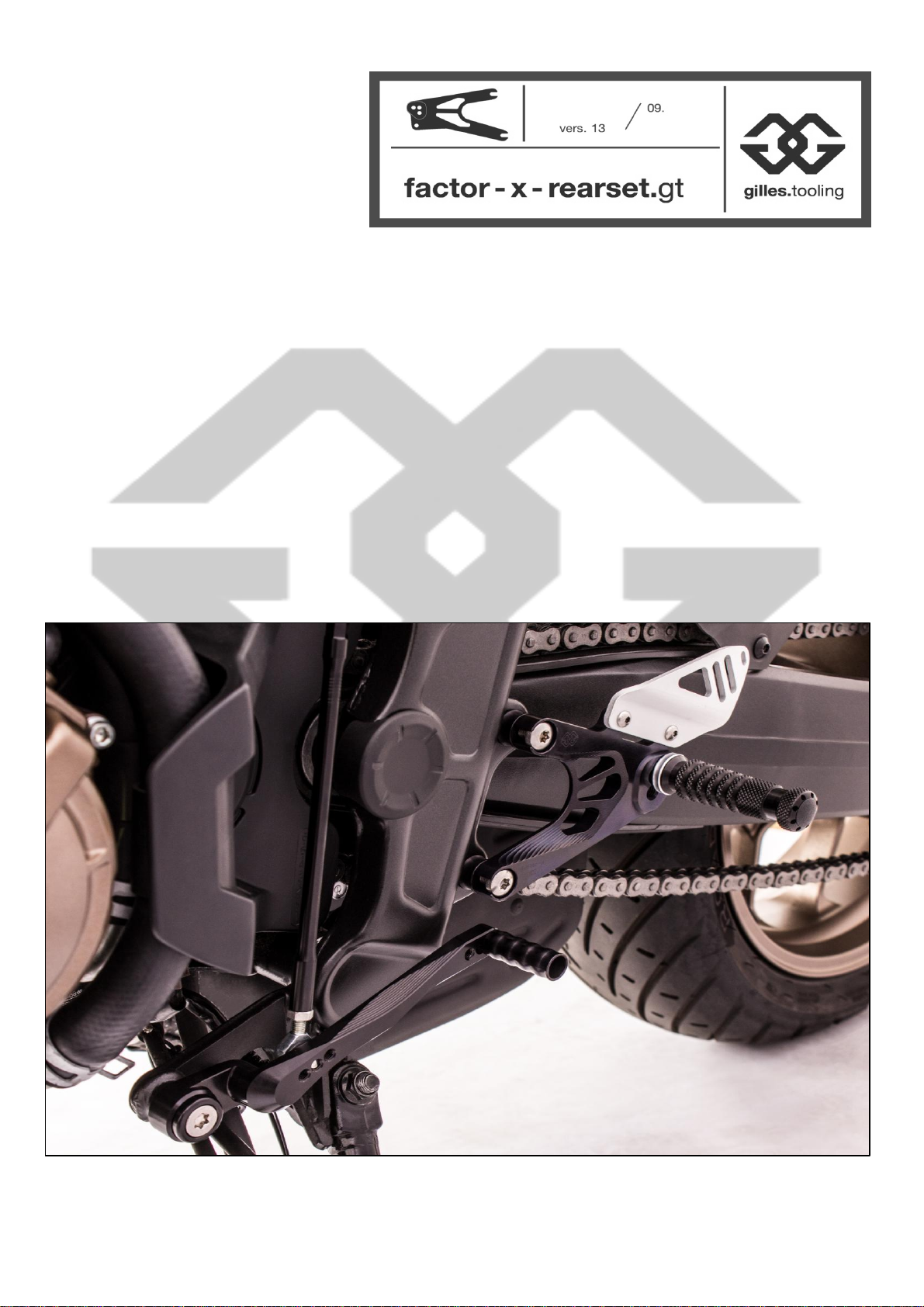
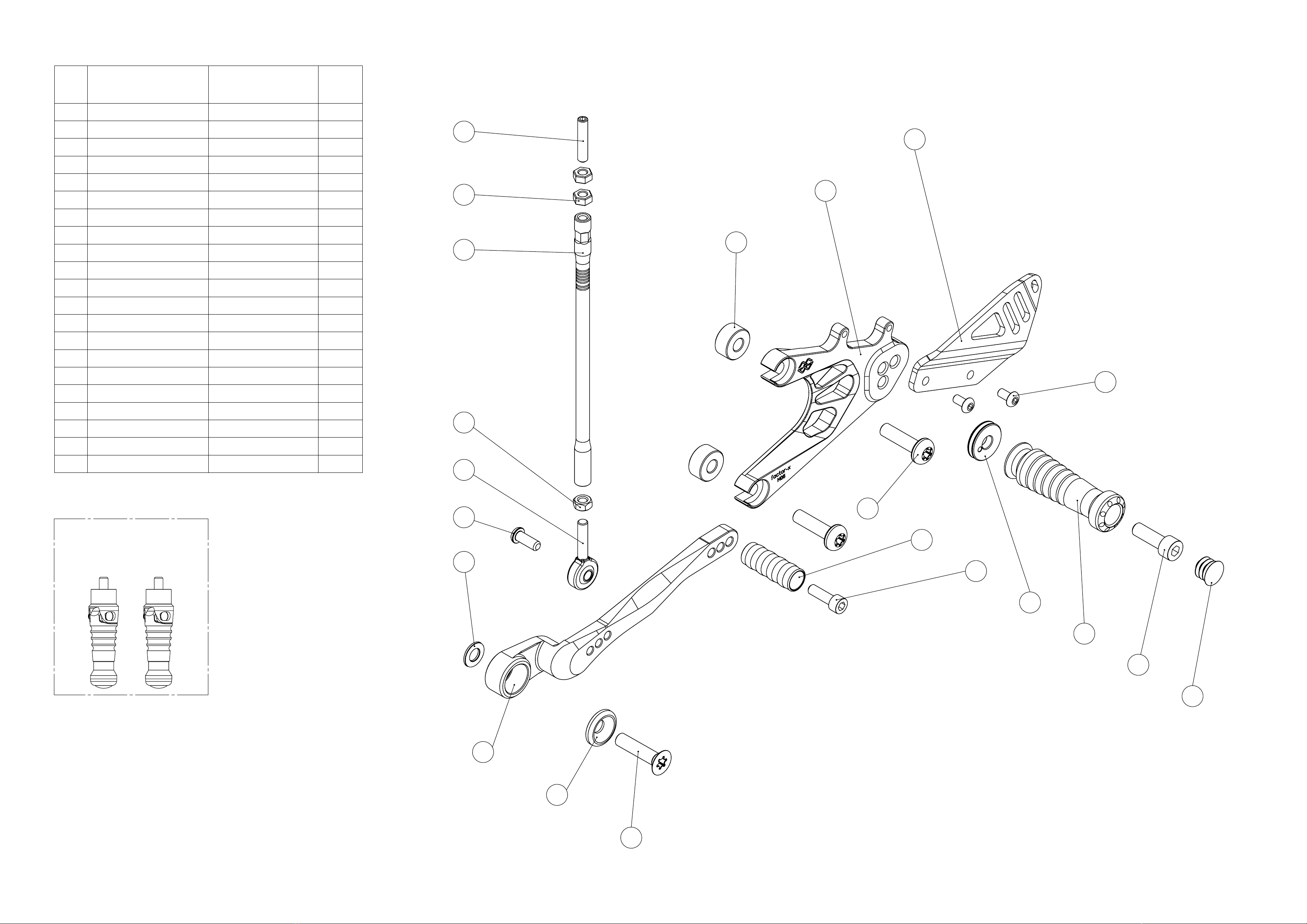
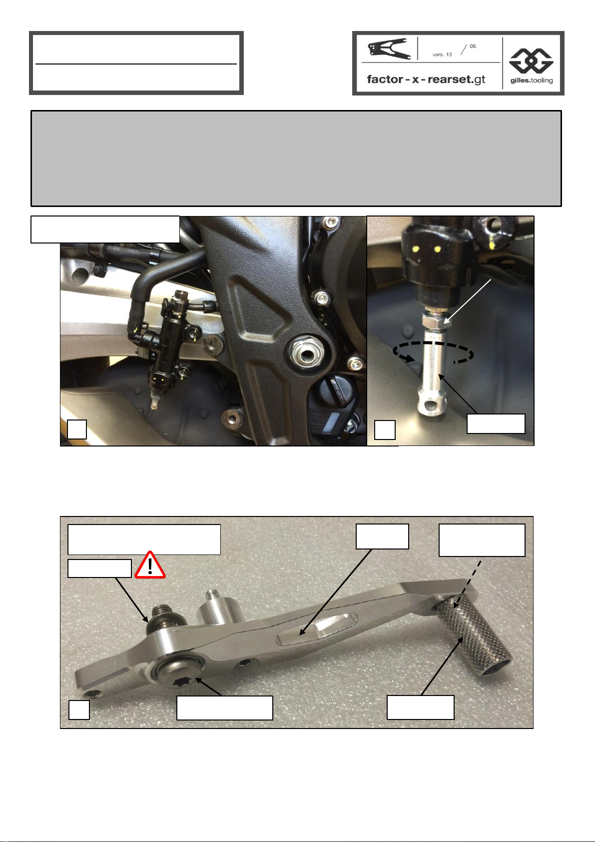
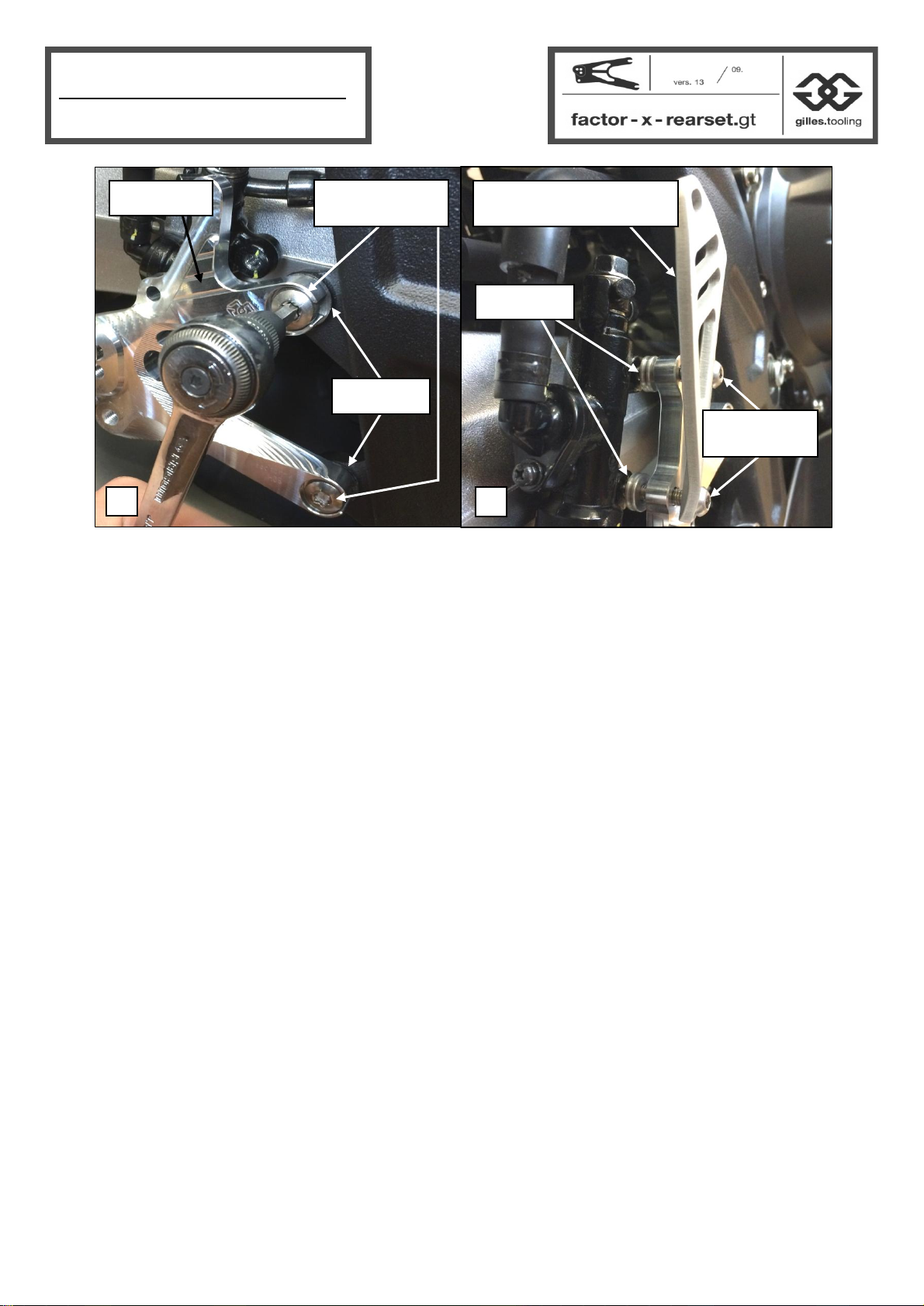
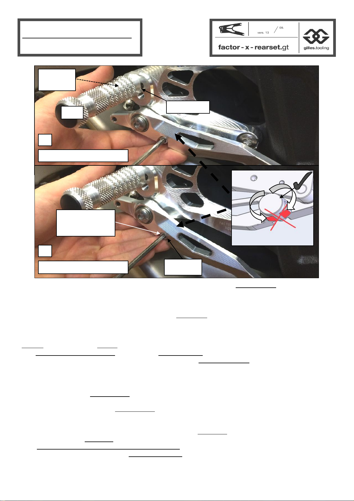
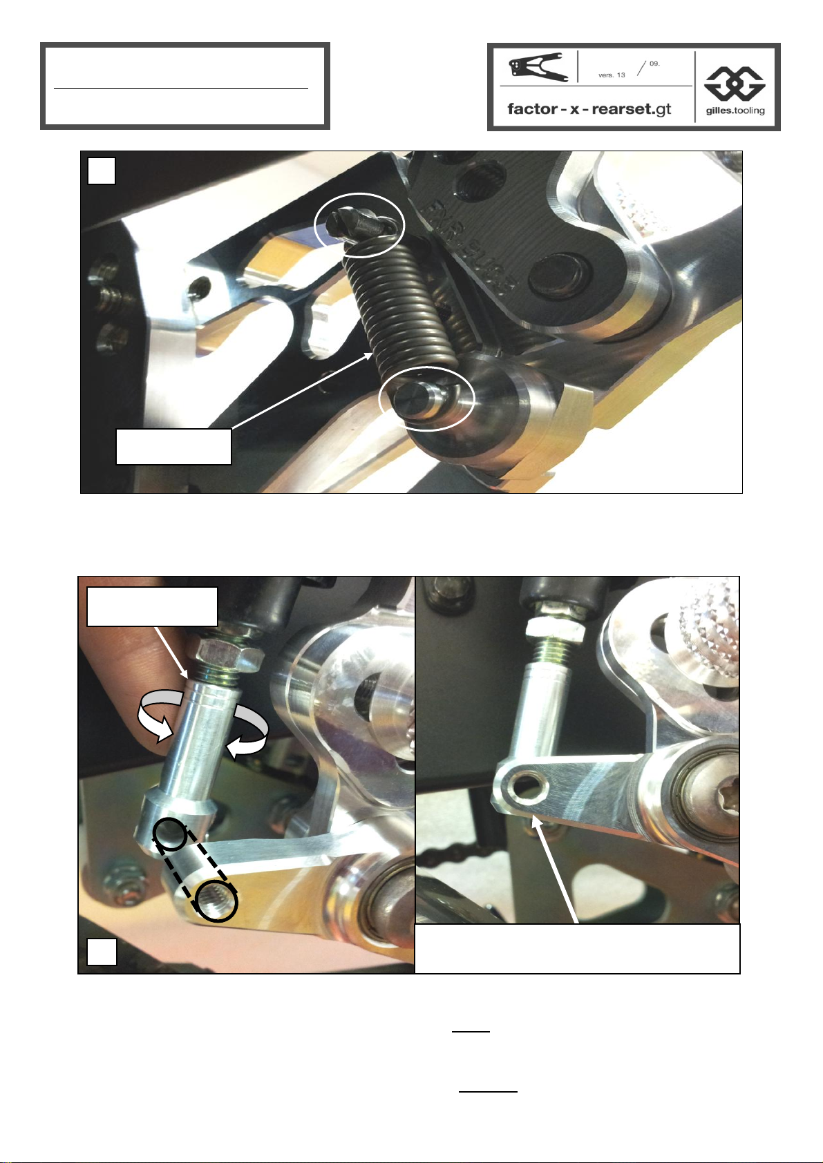
gilles.tooling factor-x-rearset.gt User manual

gilles.tooling
gilles.tooling VCR38GT User manual

gilles.tooling
gilles.tooling 1D.GT Series User manual

gilles.tooling
gilles.tooling AS31GT User manual

gilles.tooling
gilles.tooling Rct10gt- BM08 User manual

gilles.tooling
gilles.tooling FXR-Y03 User manual

gilles.tooling
gilles.tooling AS 31 GT Series User manual

gilles.tooling
gilles.tooling AS 31 GT User manual

gilles.tooling
gilles.tooling FXR-Y07-B User manual