manuals.online logo
Brands
  1. Home
  2. •
  3. Brands
  4. •
  5. gilles.tooling
  6. •
  7. Motorcycle Accessories
  8. •
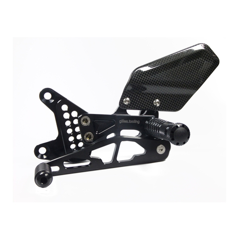
  9. gilles.tooling Rct10gt- BM08 User manual

gilles.tooling Rct10gt- BM08 User manual

Rev 01, 08/ 2018
Rct10gt- BM08
rct.rearsets
Anbauanleitung
Manual
Allgemeine Hinweise
-Ein unsicher aufgestelltes Motorrad kann bei den folgenden Arbeiten umfallen! Achten Sie darauf, dass
das Fahrzeug sicher steht.
-Verbrennungsgefahr bei heissem Motor und Auspuff! Vor Beginn der Arbeit heiße Fahrzeugteile abkühlen
lassen.
-Kinder und Tiere aus dem Arbeitsbereich fernhalten.
-Schmuck (Uhr, Ringe, Ketten, etc) vor Arbeitsbeginn ablegen.Es besteht Unfallgefahr durch Hängenbleiben
oder elektrischen Kurzschluss.
-Die Montage und Funktion bezieht sich ausschliesslich auf Serienmotorräder.
-Wir übenehmen keine Gewährleistung für die Verwendung an Sonderumbauten und von
Sonderzubehörteilen.
-Nach Montage des Produkts durch eine Werkstatt, ist diese Anbauanleitung dem Kunden auszuhändigen.
-Bewahren Sie die Anbauanleitung sorgfältig auf, und geben Sie dieses Produkt nur mit dieser
Anbauanleitung an Dritte weiter.
-Sollte die erforderliche Anleitung nicht mehr in Ihrem Besitz sein, wenden Sie sich bitte an:
info@gillestooling.com
Montagehinweise
-Alle Schrauben und Muttern werden mit Drehmoment nach DIN/ISO festgezogen. Abweichende
Drehmomente werden angegeben.
-Lagerungen und Schraubverbindungen sind mit einem geeigneten Schmiermittel einzusetzten, um ein
Festfressen zu verhindern.
-Arbeiten und Entlüftung am Bremssystems sind nur von fachkundigem Personal durchzuführen.
-Es ist unbedingt darauf zu achten, dass keine Züge, Kabel oder Leitungen (insbesondere Bremsleitungen)
andere Fahrzeugkomponenten berühren oder daran scheuern.
-Nach jeder Montage sind alle Schrauben auf festen Sitz und das vorgeschriebenes Drehmoment zu
überprüfen.
-Es ist unbedingt darauf zu achten, dass alle Teile immer einen Mindesabstand von 5mm zu beweglichen
Fahrzeugteilen haben.
Diese Anbauanleitung ist sorgfältig und vollständig vor Beginn der
Einbauarbeiten durchzulesen.
Wir bedanken uns für den Erwerb eines unserer Produkte und wünschen Ihnen viel Spaß. Machen
Sie aus einem Serienfahrzeug Ihre individuelle Maschine.
-Sicherheit ist oberstes Gebot.
-Haben Sie das erforderliche Werkzeug und genügend Mechanikerwissen und praktische Erfahrung?
-Unsere Produkte dürfen nur von fachkundigem Personal montiert werden.
-Nichtbeachtung der Anweisung kann zu Beschädigungen des Fahrzeuges, des Produktes bzw. zur
Gefährdung des Fahrers führen.
-Für Schäden, die aufgrund von Nichtbeachtung unserer Anweisungen entstanden sind, können wir keine
Haftung oder Gewährleistung übernehmen.
Betriebserlaubnis
-Beachten Sie die für Ihr Land geltenden Zulassungsbestimmungen.
-Für den Bereich der Bundesrepublik Deutschland gilt:
Ein Eintrag in die Fahrzeugpapiere ist nicht erforderlich! ABE
rct10gt-BM08
Sicherheitshinweise
rct10gt-BM08
safety instructions
You must read these installation instructions carefully and make sure you
understand everything they contain, before commencing work.
Thank you for purchasing one of our products and we wish a lot of enjoyable riding. With Gilles you
make a standard bike - your bike.
-Safety always comes first.
-Do you have the correct tools?
-Do you have the ability and aptitude to confidently mount thes product. If in doubt consult a skilled
technican.
-We always advise fitment is carried out by skilled personal.
-Non-compliance with the instructions can be hazardous. For your own protection and the safety of the bike
please always follow the instructions.
-Any Gilles parts will not be covered by warranty it fitted incorrectly.
General instructions
-Please ensure the motorcycle is adequately secured before commencing work.
-Always make sure that the motorcycle is stable and firmly supported.
-A hot engine and exhaust system can burn. Allow all hot parts to cool before commencing work.
-Keep children and household pets well away from the work zone.
-Remove all items of personal jewellry (rings, chains,wristwatch, etc.) before commencing work.
-The fitment instructions relate only to the fitment on a standart motorcycles.
-We cannot warranty or legislate for interaction or interference with non standard or custom parts.
-If a technican is installing the parts please ensure these instructions are passed to the owner.
-Please keep the instruction manual at a safe place. In case of selling our product, please hand the
installation instructions over to the new owner.
-Consult [email protected] if the instructions in question are no longer in your possession.
Operating licence
-Always comply with the regulations regarding approval in the country of use.
-For the Federal Republic of Germany:
A entry in the vehicle´s registration papers is not required ! ABE
Assembling note
-Screws, bolts and nuts are tightened in accordance with the applicable DIN/ISO standarts. Tightening
torques that deviate from the standards are stated.
-All threaded connections and bearings must be greased with suitable grease. Please be careful with the
tools to avoid i.e. scratches.
-Mounting and bleeding at the brake system only by skilled personal.
-Take care that no wires and hoses (especially brake hoses) are too close or touching other components or
moving parts.
-After each mounting check all bolts for correct tightening and specified torque moment.
-Take care that any parts always have a minimum clearence of 5 mm to any moving parts.
11 1 23 20
30
27
6
17
18
12
13
7
2628891021
5
4
29
24
2
25
15
3
14
22
19
16
pos
article no.
description
qty.
[pcs.]
1
RCT-GR-BM08-*
right basic plate
1
2
RG-A-20-*
extension
1
3
RG-870-*
footrest joint
1
4
UF-24-*
footrest
1
5
UF-ST-01-*
plug
1
6
HA-UB-27-*
holder brake lever
1
7
UB-27-*
brake lever
1
8
UEX-01
excenter
1
9
UTR-01
brake lever toe piece
1
10
BL-01
cover
1
11
CAR03-R 6,5-40-*
heel protector
1
12
HBH-MSB04
microswitch actuator
1
13 7702868
spring fixing pin
1
14
RG-BO-01
bolt RG
1
15
SIF-19078
pull spring
1
16
SPC-02
tube for spring
1
17
RZ-115NX
tension spring
1
18
SPC-01
tube for spring
1
19
d3x8-8750-VA
spiral tension pin
1
20
M6-985-VA
safety nut
2
21
M8x35-7991-VA-TX-PRE10-1
countersunk bolt
1
22
M8x25-7991-VA-TX
countersunk bolt
1
23
M8x20-912-VA-TX
cylinder bolt
2
24
M8x16-912-VA-TX-TUF
cylinder bolt
1
25
M6x25-7380-VA-TX
oval-head bolt
2
26
M6x20-7380-VA-TX-PRE10-1
oval-head bolt
1
27
M6x20-7991-VA-PRE10-1
countersunk bolt
2
28
M6x16-7991-VA-PRE10-1
countersunk bolt
1
29
M4x8-14583-VA-TX
oval-head bolt
1
30
2x10 ISO 8746-VA
grooved pin
2
1 17 11229
16 23 5198720216
10
4123 18
14
13215
pos
article no.
description
qty.
[pcs.]
1
RCT-GL-BM08-*
left basic plate
1
2
RG-A-20-*
extension
1
3
RG-870-*
footrest joint
1
4
UF-24-*
footrest
1
5
UF-ST-01-*
plug
1
6
US-36-*
gear lever
1
7
UEX-01
excenter
1
8
UTR-15
gear lever toe piece
1
9
CAR03-R 6,5-40-*
heel protector
1
10
DS22-14-6,1
distance
1
11
RG-BO-01
bolt RG
1
12
SIF-19078
pull spring
1
13
SPC-02
tube for spring
1
14
d3x8-8750-VA
spiral tension pin
1
15
ULS-6,4-VA
washer
1
16
M8x25-7991-VA-TX
countersunk bolt
1
17
M8x20-912-VA-TX
cylinder bolt
2
18
M8x16-912-VA-TX-TUF
cylinder bolt
1
19
M6x25-7380-VA-TX
oval-head bolt
1
20
M6x20-7380-VA-TX-PRE10-1
oval-head bolt
1
21
M6x16-7991-VA-PRE10-1
countersunk bolt
1
22
M6x10-7380-VA-TX
flathead bolt
2
23
M4x8-14583-VA-TX
oval-head bolt
1
-ES WIRD EMPFOHLEN DIE ANLAGE VON EINER FACHWERKSTATT INSTALLIEREN ZU LASSEN.
-INSTALLATION RECOMMENDED BY AN OFFICIAL DEALER/ WORKSHOP.
rct10gt- BM08
Anbauanleitung/ Manual
-Demontieren Sie die originale Rastenanlage (nicht dargestellt). Übernehmen Sie den originalen elektrischen Schalter
von der Serien- auf die Gilles Tooling- Rastenanlage wie in dem Bild dargestellt. Achten Sie darauf dass die
Einbaurichtung des Schalters identisch ist mit dem Bild!
Treiben Sie nun mit leichten Hammerschlägen die beiden Pins/ Bolzen 2x10 ISO8746, durch den Schalter hindurch,
in die Bohrungen der Rastenanlage (Bild 1)!
-Detach the original rearset system (not pictured). Take the original electrical switch from the serial to the Gilles
Tooling rearset like shown in the picture. Make sure that the mounting direction of the switch is the same as the
picture!
Drive in the two pins/ bolts 2x10 ISO8746, through the switch, into the holes of the rearset by slight beatings with the
hammer (picture 1)!
Originalschalter
original switch
Achtung: Einbaurichtung/ Position
Attention: Mounting direction/ position
PIN 2x10 ISO 8746
(-Die originale Betätigungsstange samt Gabeladapter weiterverwenden. Siehe Bild 2.)
-Rechte Fussrastenanlage mit den Schrauben M8x20-912-TX auf den Hauptrahmen schrauben (Bild 3).
Anzugsdrehmoment: 20 Nm
(Use the original actuacting rod and the original adaptor like picture 2 shows.)
-Install the right rearset with bolts M8x20-912-TX onto the main frame (picture 3).
Tightening torque: 20 Nm
2 3
Rechts/ right side
M8x20-912-TX
20 Nm
Originalteile
original parts
1
rct10gt- BM08
Anbauanleitung/ Manual
-Schrauben Sie den Hauptbremszylinder an die Rastenanlage wie in Darstellung 4 gezeigt! Die Schrauben M6x25-
7380-TX werden durch den Fersenschutz CAR03-R 6,5-40, die Rastenanlage und schließlich den Bremszylinder
gesteckt. Eingeschraubt wird das Schraubenende in die Sicherheitsmutter M6 (Bild 4). Anzugsdrehmoment: 10 Nm
-Zum Einstellen des Bremsspiels wird der originale Gabeladapter auf der Betätigungsstange des Bremszylinders hoch
oder runter geschraubt, sodass die Bohrung Ø 6mm des Adapters deckungsgleich mit der Bohrung Ø 6mm des
Bremshebels UB-27 liegt- Eine Flucht! (Bild 5)
-Install the master cylinder on the rearset like picture 4 shows! Put the bolts M6x25-7380-TX through the heel guard
CAR03R 6,5-40, the rearset and finally the master cylinder. Secure bolts with M6 safety nuts (picture 4).
Tightening torque: 10 Nm
-Turn the original adaptor up or down on the actuating rod of the master cylinder for doing the adjustment of the brake
clearence/ freeplay. The hole Ø 6mm of the adaptor must fall in line with the hole Ø 6mm inside the brake lever UB-
27.- Both in alignment! (picture 5)
4 5
Sicherheitsmutter
safety nut
M6-985
6
-Einstecken des originalen Clips (Bolzen Ø6mm) wie im
Detail der Darstellung 6 gezeigt durch die beiden
ausgerichteten Bohrungen. Kontern Sie anschließend
mit einem 10er Maulschlüssel die Kontermutter gegen
den Gabeladapter. (Bild 6)
-Put the original clip (pin Ø6mm) into both adjusted
holes. Counter the counter nut with a open end wrench
10 against the adapter. (picture 6)
M6x25-7380-TX
10 Nm
Originalteil
original part
-Demontieren Sie die originale Rastenanlage, sowie den Schalthebel wie in Bild A. dargestellt.
-Demount the original rearset plus the shift lever from the serrated shaft like shown in picture A.
Links/ left side
A
rct10gt- BM08
Anbauanleitung/ Manual
-Überprüfen des Bremsspieles durch Drehen des
Hinterrades und Betätigen der Bremse. (Bild 6)
Sollte das Bremsspiel durch die Einstellung nicht
ausreichen (Bremsbeläge liegen an/ schleifen) oder zu
groß sein (zu viel Leerweg bis Druckpunkt) kann durch
nochmaliges rein- oder rausdrehen des Adapters
(zurück in Schritt 5) korrigiert werden. Der Bremshebel
muss ein spürbares Spiel aufweisen.
-Test the brake freeplay by turning the rear wheel and
pressing the brake by hand. (picture 6)
If the brake clearance/ freeplay in is not enough (brake
linings fit/grind) or too much (too much lever travel until
pressure point), you can turn the adaptor in or out to
adjust it (back in step 5). The brake lever must have
noticable freeplay.
-Zum Vornehmen der folgenden Einstellung
sollte das Hinterrad frei drehbar in der Luft sein!
-For the next steps the rear wheel should be
able to turn free in the height!
7 Funktionsprüfung der Bremse!
Check the function of the brake!
-Montieren Sie den Schalthebel auf die Kerbzahnwelle (Bild C). Die Schraube M8x25-7380-TX (samt Unterlegscheibe
ULS-6,4) kann erst nach dem Aufstecken eingesetzt werden. Anzugsdrehmomnet: 8 Nm
-Install the gear lever on the serrated shaft (picture C). You can only insert the bolt M8x25-7380-TX (and the washer
ULS-6,4) after plugging the the lever on shaft. Tighten the bolt. Tightening torque: 8 Nm
C
M6x25-7380-TX
+ ULS-6,4
8 Nm
rct10gt- BM08
Anbauanleitung/ Manual
-Montage der linken Grundplatte auf die gleiche Weise wie in Schritt 3 der Bremsseite und wie in Bild B dargestellt. (2
Schrauben: M8x20-912-TX)
Anzugsdrehmoment: 20 Nm
-Stecken Sie den Distanzring DS24-14-6,1 auf die Kerbzahnwelle wie im Detail von Bild B!
-For installing the left basic plate of the rearset system, repeat the instructions in step 3 of the brake side. Compare
picture B. (2 bolts M8x20-912-TX)
Tightening torque: 20 Nm
-Put the spacer DS24-14-6,1 on the serrated shaft like shown in detail of picture B !
B
M8x20-912-TX
20 Nm
DS-22-14-6,1
-Gegebenenfalls ist der Gummianschlag des Seitenständers in der Dicke zu halbieren um eine größere Freigängigkeit
bei der Abwärtsbewegung des Schalthebels zum Seitenständer zu erreichen. (Der Schalthebel kann außerdem auch
um einen Zahn im Uhrzeigersinn verdreht und somit höher gesetzt werden falls der Abstand immer noch zu gering
sein sollte)
-For higher clearance during the downward movement of the gear lever, the stop rubber of the side stand need to be
halved in thickness (picture D) for more clearance between lever and side stand.
(The shift lever can also be turned one tooth in clockwise direction into higher position if the distance should still be
too low)
D
1 (max.)
rct10gt- BM08
Einstellungen/ Adjustments
1: Entfernen Sie die Fussrate um Ihre neue, individuelle Sitzposition auf der Fussrastenanlage einzustellen.
Ablauf auf rechter und linker Seite identisch (R=L)!
1: Remove the footpeg to adjust your new and individual ridingposition on the rearset system`s basic plate.
Procedure is on the right and left side the same (R=L)!
1.1 / 1.2: Entfernen Sie die Schraube (M4x8-14583) und den Bolzen (RG-BO-01) gemäß der Darstellungen.
1.1 / 1.2: Detach the screw screw (M4x8-14583) and the bolt (RG-BO-01) according to the pictures.
1.1
1.2
1.3
1.4
1.3: Ziehen Sie am Rastenkörper (a) und schwenken Sie diesen aus dem Gelenk (RG-870) heraus (b).
1.4: Demontieren Sie die Schraube M8x16-912-TX und somit das Gelenk RG-870.
1.3: Pull at the footpeg (a) and slide it outside the joint (RG-870) according to the picture (b).
1.4: Disassemble the screw M8x16-912-TX and thus the joint like the picture shows. It follows
b
a
RG-870
2.1
R=L
2 Fußrastenausleger (RG-A-20) versetzen: Wählen Sie eine Fahrerposition (1-7) gemäß Darstellung 5.
2 Adjustment of the footpeg extension (RG-A-20): Choose a new, indiviual position (1-7) according to picture 5.
RG-870
7 (min.)
1-7
20 Nm
2.2
2.3
3
3 Einstellvorgabe: Fußraste darf nur nach oben und leicht nach hinten klappen (ca. 45 Winkelgrad).
3 Adjustment specification: The footrest may only fold upwards and slightly towards the rear (approx. 45 degrees).
4:-Schraube M8x16-912-TX, Anzugsdrehmoment: 20Nm
-Schraube M4x8-14583, handfest
-Bolzenkopf nach OBEN!
4:-Screw M8x16-912-TX, tightening torque: 20Nm
-Screw M4x8-14583, hand- tight
-bolt head UPWARDS!
4: Montieren Sie die Fussraste in umgekehrter Reihenfolge zur Demontage (Schritte 1.1 bis 1.4).
4: Install the footpeg in turned direction to the disassembling steps (step 1.1 till 1.4).
4
rct10gt- BM08
Einstellungen/ Adjustments
2.1: Die Zentralschraube entfernen um den Fußrastenausleger (RG-A-20) auf der Verzahnung neu zu positionieren.
2.2: ACHTUNG: Es ist nur der Einstellbereich von 1-7 zulässig! Orientieren Sie sich an den 7 gravierten Markierungen.
2.3: Nach dem Verstellen ist die Schraube wieder zu montieren! Anzugsdrehmoment: 20Nm
2.1: Loosen the central bolt to reposition the footpeg extension (RG-A-20) on the rearset`s gearing!
2.2: You have to do the adjustment in the range of position 1 till 7! Take notice on the engraved lines on the basic plate.
2.3: You have to tighten the bolt again after doing the adjustment! Tightening torque: 20Nm
6: Trittstückverstellung
-Zur Verstellung des Trittstückes ist die Schraube M6x20-
7380-TX zu entfernen (Doppelexzenter) oder zu lösen.
-Die zweite Bohrung kann ebenfalls zur Positionierung
genutzt werden. (Schalt-, sowie Bremsseite!)
-Trittstück drehbar einstellen und Schraube festziehen.
Anzugsdrehmmente: 10Nm
6: Toe piece adjustment
-Remove (double excentric) or loosen the bolt M6x20-
7380-TX to adjust the toe piece.
-The second hole can also be used and offers more
options to adjust. (at the shift-, and brake side!)
-Turn the toe piece to desired position at the excentric and
re-tighten bolt.
Tightening torques: 10Nm
R=L
6
10 Nm
rct10gt- BM08
Einstellungen/ Adjustments
5
Pos. Description Part-No. Qty. OK
1screw M8x20-912-VA-TX 4
2screw M6x25-7380-VA-TX 2
3safety nut M6-985-VA 2
4spacer DS22-14-6,1- (N) 1
5grooved pin 2x10 ISO 8746-VA 2
6heel guard
CAR03-R 6,5-40- B1
7manual Rct10gt-BM08-ABA 1
8certificate ABE- 91249 1
MA
Datum
Revision 01 , Stand 08/18
rct10gt- BM08
Packzettel/ Packing List

Other gilles.tooling Motorcycle Accessories manuals

gilles.tooling AS 31 GT User manual

gilles.tooling

gilles.tooling AS 31 GT User manual

gilles.tooling VCR38GT User manual

gilles.tooling

gilles.tooling VCR38GT User manual

gilles.tooling m2-MV01 User manual

gilles.tooling

gilles.tooling m2-MV01 User manual

gilles.tooling MUE2-D01 User manual

gilles.tooling

gilles.tooling MUE2-D01 User manual

gilles.tooling AS 31 GT Series User manual

gilles.tooling

gilles.tooling AS 31 GT Series User manual

gilles.tooling AS31GT User manual

gilles.tooling

gilles.tooling AS31GT User manual

gilles.tooling FXR-Y07-B User manual

gilles.tooling

gilles.tooling FXR-Y07-B User manual

gilles.tooling AS 31 GT Series User manual

gilles.tooling

gilles.tooling AS 31 GT Series User manual

gilles.tooling factor-x-rearset.gt User manual

gilles.tooling

gilles.tooling factor-x-rearset.gt User manual

gilles.tooling MPCL-02 User manual

gilles.tooling

gilles.tooling MPCL-02 User manual

gilles.tooling RCT10GT-K02 User manual

gilles.tooling

gilles.tooling RCT10GT-K02 User manual

gilles.tooling K08 User manual

gilles.tooling

gilles.tooling K08 User manual

gilles.tooling AS 31 GT User manual

gilles.tooling

gilles.tooling AS 31 GT User manual

gilles.tooling 1D.GT Series User manual

gilles.tooling

gilles.tooling 1D.GT Series User manual

gilles.tooling fxr.rearsets-H05 User manual

gilles.tooling

gilles.tooling fxr.rearsets-H05 User manual

gilles.tooling Rct10gt-S02 User manual

gilles.tooling

gilles.tooling Rct10gt-S02 User manual

gilles.tooling rct10gt- Y02 User manual

gilles.tooling

gilles.tooling rct10gt- Y02 User manual

gilles.tooling FXR-Y03 User manual

gilles.tooling

gilles.tooling FXR-Y03 User manual

Popular Motorcycle Accessories manuals by other brands

GÜDE GSH 180-TC-2 Translation of the original instructions

GÜDE

GÜDE GSH 180-TC-2 Translation of the original instructions

BorMann BWH1000 manual

BorMann

BorMann BWH1000 manual

hepco & becker 730.952 manual

hepco & becker

hepco & becker 730.952 manual

Trail Tech ENDURANCE II manual

Trail Tech

Trail Tech ENDURANCE II manual

Dynojet Power commander V installation instructions

Dynojet

Dynojet Power commander V installation instructions

Nolan N70-2 GT Safety and instructions for use

Nolan

Nolan N70-2 GT Safety and instructions for use

Free Spirits 208921 instructions

Free Spirits

Free Spirits 208921 instructions

Tipperary Sportage How to fit

Tipperary

Tipperary Sportage How to fit

Sena RC4 quick start guide

Sena

Sena RC4 quick start guide

Sundstrom SR 592 Instructions for use

Sundstrom

Sundstrom SR 592 Instructions for use

KTM 60712933050 Information

KTM

KTM 60712933050 Information

Hogtunes 692 XL LID-RM installation manual

Hogtunes

Hogtunes 692 XL LID-RM installation manual

HJC SMART 50B user guide

HJC

HJC SMART 50B user guide

Bagster BOOMERANG 7554CB Fitting instructions

Bagster

Bagster BOOMERANG 7554CB Fitting instructions

PUIG 9283 quick start guide

PUIG

PUIG 9283 quick start guide

Kobalt SGY-A14 manual

Kobalt

Kobalt SGY-A14 manual

hepco & becker 7007556 00 01 Mounting instructions

hepco & becker

hepco & becker 7007556 00 01 Mounting instructions

eBike KT-LCD1 user manual

eBike

eBike KT-LCD1 user manual

manuals.online logo
manuals.online logoBrands
  • About & Mission
  • Contact us
  • Privacy Policy
  • Terms and Conditions

Copyright 2025 Manuals.Online. All Rights Reserved.