GLP X4 ATOM series User manual

Instruction Manual
series
preliminary version 0.1

Notes:

German Light Products GmbH WWW.GLP.DE
X4 Atom User Manual (v.0.3) 3
Table of contents
1Parts Identification..................................................................................................4
1.1 Power Supply Unit (PSU) ........................................................................................................... 4
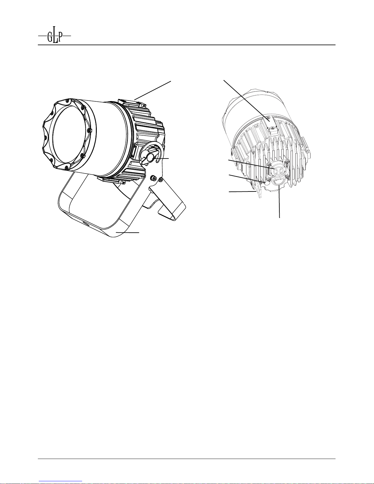
1.2 X4 Atom Head ............................................................................................................................ 5
2Safety Precautions..................................................................................................6
3Mounting..................................................................................................................8
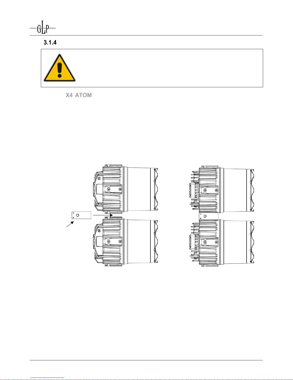
3.1 X4 ATOM Heads......................................................................................................................... 8
3.2 PSU Installation........................................................................................................................ 11
4Connections ..........................................................................................................12
4.1 AC Power.................................................................................................................................. 12
4.2 DMX Data ................................................................................................................................. 12
4.3 X4 ATOM heads ....................................................................................................................... 12
5Accessories...........................................................................................................13
5.1 ATOM Trussbar........................................................................................................................ 13
6User settings, utilities, and readouts...................................................................14
7Effects....................................................................................................................16
7.1 Master Intensity ........................................................................................................................ 16
7.2 Special Functions ..................................................................................................................... 16
7.3 Intensity..................................................................................................................................... 16
7.4 Shutter ...................................................................................................................................... 16
7.5 Fixed Colors (RGBW model).................................................................................................... 16
7.6 Color Mixing (RGBW model) / White Balance (Tunable White model) .................................... 17
7.7 Zoom......................................................................................................................................... 17
7.8 Color Correction........................................................................................................................ 17
8DMX Channels.......................................................................................................18
8.1 Normal Mode, RGBW Heads: 56/110 DMX Channels............................................................. 18
8.2 Normal Mode, Tunable White Heads: 38/74 DMX Channels................................................... 19
8.3 Compressed Mode, RGBW Heads: 38/74 DMX Channels...................................................... 20
9Cleaning and Maintenance...................................................................................21
9.1 Cleaning.................................................................................................................................... 21
9.2 Fuse replacement..................................................................................................................... 21
10 Technical Specifications ......................................................................................22
10.1 X4 Atom RGBW and CWWW Head Specifications.................................................................. 22
10.2 X4 ATOM PSU12 Specifications .............................................................................................. 23
10.3 X4 ATOM PSU6 Specifications ................................................................................................ 24
11 Dimensions............................................................................................................25
11.1 X4 Atom Head Dimensions ...................................................................................................... 25
11.2 X4 Atom PSU 12 Dimensions................................................................................................... 26
11.3 X4 Atom PSU6 Dimensions...................................................................................................... 27

German Light Products GmbH WWW.GLP.DE
4 X4 Atom User Manual (v.0.1)
air vent
1 Parts Identification
1.1 Power Supply Unit (PSU)
12-output PSU shown. 6-output PSU similar.
LCD display and
control buttons
clamp attachment point
ATOM power and data outputs
power switch
fuse holder
AC input
AC output
DMX input
DMX output
Sockets for Omega bracket attachment

German Light Products GmbH WWW.GLP.DE
X4 Atom User Manual (v.0.3) 5
tilt lock
screw
vent plug
1.2 X4 Atom Head
ATOM Connector
sockets (4)
yoke/floor stand
ATOM power and data input:
Connect to ATOM PSU ONLY!
fan
safety cable
attachment

German Light Products GmbH WWW.GLP.DE
6 X4 Atom User Manual (v.0.1)
2 Safety Precautions
The
X4 Atom
is powerful lighting equipment intended for use by
experienced lighting professionals. Read this manual before
installation or use. For safe and trouble-free operation, install and
use only as directed.
The manufacturer will take no responsibility for damages caused by
disregard for the information in this manual. Warranty claims will be
invalidated if any piece of the product casing has been removed.
Attention: Class 2M LED. Brief exposure can cause eye injury
within a distance of 0.5 m (20 in.), even without optical instruments.
Never look directly into the beam of light or into the LED.
Avoid exposing your eyes to direct radiation!
The X4 ATOM
is fitted with a plano-
convex lens that focuses and
concentrates light just like a
magnifying glass. Direct sunlight
and other bright light sources can
cause internal damage to the fixture. With a high-power light
source, this can happen quickly, potentially melting components or
starting an internal fire within seconds.
Potentially hazardous light concentration can occur whether fixtures
are powered on or off. To avoid problems, observe the following
precautions at all times:
Never expose the front of a fixture to direct sunlight or any other
strong light sources.
For outdoor applications during daylight, make sure that the front
face of any fixture is either shielded or points away from the sun,
even when fixtures are not in use.
Do not modify the front glass or lens of any fixture.
Especially when working with high powered beam lights, extreme
caution and observance of these safety instructions is mandatory.
Also note the following requirements to ensure safe operation.
1. Before powering up the lights, ensure that fans and air vents are clean and
unobstructed.
2. Maintain a minimum distance of 0.5 m (20 in.) between lighting heads and any
flammable object.
3. Hot surfaces! Avoid touching lights during the operation. This can cause injuries
and/or damage.

German Light Products GmbH WWW.GLP.DE
X4 Atom User Manual (v.0.3) 7
4. The PSU and lighting head contain no user-serviceable parts. Opening the PSU or
lighting head will void all warranties.
5. Wait at least 15 minutes after turning the system off to handle lighting heads. Handle
carefully and be aware that some surfaces may be extremely hot.
6. Install X4 ATOM system components as directed below with suitable clamps and
other hardware including safety cables. Avoid placing lighting heads in locations
where there is risk of accidental contact.
7. Repair, maintenance and installation work shall be performed only by GLP- certified
technicians or other qualified lighting professionals. These operations require
common trade knowledge that is not explicitly provided in this manual.
8. Use only original spare parts. Any structural modification on the system will
terminate all warranty claims.
9. Keep this user manual for future reference.
Should you have any questions about the safe operation of your X4 ATOM, please
contact your local GLP office, or their authorized distributor, a list of which can be found
at www.glp.de.

German Light Products GmbH WWW.GLP.DE
8 X4 Atom User Manual (v.0.1)
3 Mounting
Installation shall be performed by qualified personnel only, in
accordance with applicable regulations such as BGV C1 and DIN
VDE 0711-217.
3.1 X4 ATOM Heads
With an IP 65 rating, the X4 ATOM heads are suitable for outdoor use. (The PSU
however must be installed in a dry location.) Heads may be rigged in any orientation or
placed on a level surface. When installing, keep the lighting head at least 0.5 m (20 in.)
from flammable materials including curtains and stage scenery.
Accessories are available to mount the X4 ATOM in a range of configurations. These
fasten quickly and securely to the ATOM connectors.

German Light Products GmbH WWW.GLP.DE
X4 Atom User Manual (v.0.3) 9
Attaching the Yoke Bracket / Floor Stand
The yoke bracket / floor stand snaps on to the
connector sockets on the outside of the head.
To attach to a bracket to an X4 ATOM head,
slide the bracket forwards onto two connector
sockets until the bracket locks in place.
To release the bracket, push the lock pins on
both sides of the bracket an slide backwards.
Operating on the Floor (Upright)
The X4 ATOM can be placed upright on a floor
or other level surface using the included yoke
bracket/floor stand unfolded as shown to right.
Attach the bracket as described above. Loosen
the tilt lock screw, spread the inner and outer
brackets, tilt the head to the desired angle, and
tighten the tilt lock screw.
Hanging a single head
Heads can be rigged individually on a truss
using a suitable rigging clamp fastened to the
yoke bracket/floor stand as shown. Loosen the
tilt lock screw to adjust tilt angle. Secondary
attachment is also required.
Push pins to release

German Light Products GmbH WWW.GLP.DE
10 X4 Atom User Manual (v.0.1)
Mounting in a multiple array or matrix setup
Multiple X4 ATOM heads can easily be physically joined using the ATOM connector
included with each head to create columns, matrixes, and other configurations,
particularly when combined with the X4 ATOM Trussbar and rigging accessories. See
page 13 for more information.
To start connecting heads, attach the connector to the first head by sliding it forward
onto a connector socket from the back of the head. Then slide the connector socket of
the second head backwards onto the other side of the connector. Verify that each head
is securely locked to the connector.
To remove an ATOM connector from a socket, press the pin to unlock. Slide the
connector backwards off of the socket.
Up to twelve X4 ATOM heads can be connected vertically in a single column. Do not
hang more than 1 X4 ATOM horizontally to either side of the suspended head. Secure
each head with a separate safety cable.
Do not hang more than 12 X4 ATOM heads from a single point.
Do not connect more than 1 X4 ATOM head to either side of the
suspended head.
Secure each X4 ATOM head with its own safety cable.
ATOM Connector
(GLP #767004)

German Light Products GmbH WWW.GLP.DE
X4 Atom User Manual (v.0.3) 11
Secondary Attachment
Whenever the X4 ATOM is suspended above
ground, a safety cable must be used to prevent
injury in case the primary attachment fails. The
head has a dedicated point for attaching a safety
cable at the back. The attachment point swivels in
and out as shown.
For safe and proper fastening, the safety cable
must comply with BGI 810-3 (EN 60598-2-17
Section 17.6.6) and be capable of bearing a static
suspended load that is ten times the weight of the
fixture and all installed accessories.
When suspending multiple heads from a single clamp or other primary attachment,
secure each head with its own safety cable.
3.2 PSU Installation
The X4 ATOM PSU can be suspended with a rigging clamp or placed in a rack or on a
level surface. It has an IP 22 rating and must be installed in a dry location.
When placed on a level surface or inside a rack, additional securing is usually not
required. Provide at least 10 cm (4 in.) clearance on each side for ventilation. Ensure
that the air vents on either side are not blocked.
If using a rigging clamp to hang the X4 ATOM PSU, the clamp can be fastened to the
PSU using an omega bracket or bolted directly to the unit with an M10 x 11 mm bolt.
NOTE: Never use a bolt longer than 11 mm as this may damage the device.
Whenever suspended above ground, a
safety cable must be used to prevent injury
in case the primary attachment fails. Pass
the safety cable through a safety
attachment point shown to right.
For safe and proper fastening, the safety
cable must comply with BGI 810-3 (EN
60598-2-17 Section 17.6.6) and be
capable of bearing a static suspended
load that is ten times the weight of the
fixture and all installed accessories.
safety attachment point
2 safety attachment
points

German Light Products GmbH WWW.GLP.DE
12 X4 Atom User Manual (v.0.1)
4 Connections
Connect the
X4 ATOM
head only to an
X4 ATOM PSU
. Connecting
the lighting head to any other device may cause damage.
Never connect any other equipment to the PSU. Doing so may
damage the PSU and/or the device.
4.1 AC Power
Use NEUTRIK® powerCON locking 3
conductor AC connectors to connect the
X4 ATOM PSU to ~90-240 Volt, 50-60 Hz
AC power.
To prevent arcing and potential damage
to the connector, flip the AC power switch
to “O” (off) before connecting or
disconnecting the AC power cable.
The AC connections are color coded. Use a blue powerCON to supply power at the AC
input socket.
The grey AC output socket may be used to supply up to 18 A to additional devices.
Connect a suitable cable to the AC output with a grey powerCon connector. Check the
current draw of the connected devices and do not exceed a total of 18 A. The maximum
total current load in the AC daisy chain is 20A including the first PSU.
4.2 DMX Data
The X4 ATOM PSU provides 5-pin male and female XLR sockets for USITT DMX-512
Standard data input and throughput.
Pin 1 = [Ground] / Pin 2 = [-] / Pin 3 = [+] / Pin 4 & 5 N.C.
4.3 X4 ATOM heads
Connect X4 ATOM heads to the X4 ATOM PSU with suitable signal and power cables
fitted with 4-pin XLR connectors. To ensure the IP65 rating of the head, you must
use an IP65 rated XLR female connector such as the NEUTRIK® X-HD Series.
The connections are:
Pin 1 = [Ground] / Pin 2 = [Data +] / Pin 3 = [Data -] / Pin 4 = [V+ 24V]
The maximum cable length is 60 m (200 ft.).
Connect only one (1) GLP X4 ATOM head per PSU output.

German Light Products GmbH WWW.GLP.DE
X4 Atom User Manual (v.0.3) 13
5 Accessories
5.1 ATOM Trussbar
The X4 ATOM Trussbar (GLP #767005) holds a row of 4 X4 ATOM heads to which
additional heads may be connected easily with ATOM Connectors to assemble a matrix
up of up to 4 by 12 heads.
The Trussbar’s coupler attachment slots allow the couplers to be positioned between
the bracing of any truss. The alignment pins ensure a precise end-to-end installation of
multiple units.
alignment pins
sliding coupler attachment points

German Light Products GmbH WWW.GLP.DE
14 X4 Atom User Manual (v.0.1)
6 User settings, utilities, and readouts
The LCD display on the X4 ATOM PSU
provides access to user settings, utilities, and
readouts.
The top line displays the PSU firmware
version, head firmware version, DMX mode,
and dimming mode.
The DMX mode options are N (normal),W
(white), and C (compressed).
The dimming mode options are L (linear), S (soft), and E (extra soft).
For example, “V1.00/05/NS” indicates that the PSU is running ver. 1.00 firmware on its
CPU with ver. 05 head firmware. It is set for Normal DMX mode and Soft dimming mode.
Press Mode to enter the menu. Use Up/Down keys to scroll options. Press Enter to get
to the next level or confirm selection. Press Mode to cancel and return to the main menu.
MODE - ENTER
Remarks
DMX Start Address
1-511
DMX start address for PSU
DMX LED Start Address
1-504
DMX start address for output 1
Special
Manual DMX
Output commands without a controller
Master Intensity
0-255
Set Master Intensity level
Fixture
1-12
Select fixture/output to control
Zoom
0-255
Set zoom level
Special
0-255
Set Special functions
White Temperature
0-255
Set Color temperature level
Dimmer
0-255
Set Dimmer level
Shutter
0-255
Set Shutter level
White
0-255
Set White level
Blue
0-255
Set Blue level
Green
0-255
Set Green level
Red
0-255
Set Red level
Color Wheel
0-255
Set color wheel level
Adjust
Key code
xxxx
Enter code to unlock Adjust menu1
Display Contrast
-8 to 8
Adjustment for the Display contrast
PWM Freq. Adj.
582-618
Adjust PMW frequency2
Max Zoom adjust
-99 to 99
Calibration of Zoom-offset
Self Inspection
-
Runs a self-diagnostic test and checks
head firmware
1
For service personnel. Contact GLP Service to obtain code.
2
PMW freq. can also be adjusted by DMX.
V1.00/05/NS
PSU firmware
Head Firmware
DMX mode
Dimming mode

German Light Products GmbH WWW.GLP.DE
X4 Atom User Manual (v.0.3) 15
LED adjust
White adjust red
-99 to 99
Adjust red channel intensity
White adjust blue
-99 to 99
Adjust blue channel intensity
White adjust green
-99 to 99
Adjust green channel intensity
White adjust white
-99 to 99
Adjust white channel intensity
Offset adjust red
-99 to 99
Red calibration
Offset adjust green
-99 to 99
Green calibration
Offset adjust blue
-99 to 99
Blue calibration
Offset adjust white
-99 to 99
White calibration
Fixture
1-12
Select head to adjust
Default full feature
-
Reset all settings to factory defaults
Display Black out
ON/OFF
Darken display after 10 seconds
DMX hold
ON/OFF
Holds last DMX signal in case of signal loss
Set DMX Image
Set image if DMX off
ON/OFF
Activates a stored scene if DMX is off
Save image in memory
-
Stores the current scene for later recall
Set dimming mode
Linear dimming
-
Select linear dimming curve
Extra soft dimming
-
Select extra soft dimming curve
Soft dimming
-
Select soft dimming curve
DMX input monitor
Read DMX levels
Master Intensity
0-255
Display Master Intensity DMX value
Fixture
1-12
Select output to monitor
Zoom
0-255
Display Zoom DMX value
Special
0-255
Display Special Functions DMX value
White Temperature
0-255
Display color temperature DMX value
Dimmer
0-255
Display Dimmer DMX value
Shutter
0-255
Display Shutter DMX value
White
0-255
Display White DMX value
Blue
0-255
Display Blue DMX value
Green
0-255
Display Green DMX value
Red
0-255
Display Red DMX value
Color Wheel
0-255
Display color wheel DMX value
Self-test program
ON/OFF
Initiates a self-test program
Live time
0-99999
Total operating hours (PSU)
Set DMX Mode
Set head type and DMX option
DMX RGBW mode
-
RGBW heads, Normal DMX mode
DMX White mode
-
White heads, Normal DMX mode
DMX Compressed mode
-
RGBW heads, Compressed DMX mode
Silent Mode
ON/OFF
Control head cooling fans
Reset
ON/OFF
RESET all functions

German Light Products GmbH WWW.GLP.DE
16 X4 Atom User Manual (v.0.1)
7 Effects
7.1 Master Intensity
The master dimmer applies to all outputs and is available in all DMX modes.
7.2 Special Functions
The Special Functions apply to all outputs and are available in all DMX modes. These
functions allow you to:
Enable Silent mode. In Silent mode, the head cooling fans are switched off. The
heads will run hotter and automatically switch off the LED if they overheat, but can
run without fan cooling for extended periods in many situations. Note that operating
at higher temperatures may shorten product life. To enable Silent mode, hold the
level for 1 second. To cancel Silent mode, set the channel to No Function.
Change Pulse Width Modulation (PWM) frequency. The PWM frequency is variable
from 582 to 618 Hz. The default is 600 Hz (DMX level 150) Changing the PWM
frequency may remove banding or other artifacts from video signals. Check video
with lights at full intensity and experiment with the PWM frequency for best results.
To change the PWM frequency, hold a level for 1 second. To store a setting, hold
the level for three seconds. The heads will retain this value until a factory reset is
performed or the PWM frequency is re-adjusted via DMX or the control panel.
Synchronize all fixtures with output 1. For synchronized control of all fixtures, you
can force the PSU to copy the DMX levels on output 1 to all other outputs. To initiate
synchronized control, hold the level for 0.5 seconds. To resume individual fixture
control, set the channel to No Function.
Reset all fixtures. If necessary, you can force all heads to reset. To execute the reset
command, hold the level for 0.5 seconds.
7.3 Intensity
The dimming level of each head is controllable in the Normal DMX modes. It is not
available in Compressed DMX mode. Three dimming modes are available: Linear, Soft,
and Extra Soft.
7.4 Shutter
Shutter effects are available in all DMX modes. The shutter channels provides random
and variable-speed pulsing light effects at up to 10 flashes per second.
Caution: flashing light, particularly between 5 and 30 flashes per second, may
cause seizures in persons with photosensitive epilepsy.
7.5 Fixed Colors (RGBW model)
The RGBW model provides a virtual color wheel with 12 named colors and 3 white
tones. In addition, it provides a variable speed Rainbow Effect and variable speed
random colors.
Note that Fixed Colors override color mixing. To enable RGBW color mixing, take the
Fixed Colors channel down to 0%.

German Light Products GmbH WWW.GLP.DE
X4 Atom User Manual (v.0.3) 17
7.6 Color Mixing (RGBW model) / White Balance (Tunable White model)
The RGBW model provides control of the mix of red, green, blue, and white in Normal
and Compressed modes.
The Tunable White model provides control of the mix of cool white and warm white
LEDs. Color temperatures from approximately 2700K to 10,000K can be achieved.
7.7 Zoom
The zoom function is available in all DMX modes. It allows you to vary the beam angle
from a narrow 3.5° spot to a wide 34° flood.
7.8 Color Correction
Color correction from 2700K to 10,000K is available on both the RGBW and Tunable
White models in Normal DMX mode. It is not available in Compressed DMX mode.
Color correction can be applied on top of a color (or white tone) programed with other
channels. It can also be applied to fixed colors on the RGBW model.

German Light Products GmbH WWW.GLP.DE
18 X4 Atom User Manual (v.0.1)
8 DMX Channels
8.1 Normal Mode, RGBW Heads: 56/110 DMX Channels
Channel1
Function
%
DMX
1
Master Intensity (all outputs), 0-100%
0-100
0-255
2
Special Functions
No function
Silent mode (>1 sec)
No function
PWM Frequency: 582 Hz-618 Hz (>1 sec)
Control all (copy output 1 to all outputs) (>0.5 sec)
Reset all fixtures (>0.5 sec)
0-19
20-25
26-39
40-78
79-97
98-100
0-50
51-64
65-99
100-200
201-247
248-255
Output
Individual Head Functions
%
DMX
(1)
(2)
(3)
(4)
(5)
(6)
(7)
(8)
(9)
(10)
(11)
(12)
3
12
21
30
39
48
57
66
75
84
93
102
Intensity, 0-100%
0-100
0-255
4
13
22
31
40
49
58
67
76
85
94
103
Shutter
Shutter closed
Random strobe, slow to fast
Ramp up, random / slow to fast
Ramp down, random / slow to fast
Pulse, random / slow to fast
Strobe with b/o pause, random / slow to fast
Strobe, slow to fast
Shutter open
0-5
6-18
19-31
32-43
44-56
57-78
79-94
95-100
0-15
16-47
48-79
80-111
112-143
144-199
200-239
240-255
5
14
23
32
41
50
59
68
77
86
95
104
Fixed Colors2
RGBW control
Red
Amber
Warm Yellow
Yellow
Green
Turquoise
Cyan
Blue
Lavender
Mauve
Magenta
Pink
White –CTO, 3200K
White, 5600K
White –CTB, 7200K
Rainbow Effect Stop
Rainbow Effect, slow to fast
Random Colors, slow to fast
0-2
3-5
6-8
9-12
13-15
16-18
19-21
22-24
25-27
28-30
31-34
35-37
38-40
41-43
44-46
47-49
50
51-88
89-100
0-7
8-15
16-23
24-31
32-39
40-47
48-55
56-63
64-71
72-79
80-87
88-95
96-103
104-111
112-119
120-127
128
129-223
224-255
6
15
24
33
42
51
60
69
78
87
96
105
Color mixing: Red
0-100
0-255
7
16
25
34
43
52
61
70
79
88
97
106
Color mixing: Green
0-100
0-255
8
17
26
35
44
53
62
71
80
89
98
107
Color mixing: Blue
0-100
0-255
9
18
27
36
45
54
63
72
81
90
99
108
Color mixing: White
0-100
0-255
10
19
28
37
46
55
64
73
82
91
100
109
Zoom, wide (flood) to narrow (spot)
0-100
0-255
11
20
29
38
47
56
65
74
83
92
101
110
Color Correction
no function
Color correction: 10,000K to 2700K
0-3
4-100
0-7
8-255
1
ATOM PSU-6 requires 56 channels, ATOM PSU-12 requires 110 channels. We suggest patching the PSU as a 2-channel fixture and
each connected Atom head as a 9-channel fixture.
2
Any of the 12 named colors (excluding white) may be used to start a synchronized rainbow effect.

German Light Products GmbH WWW.GLP.DE
X4 Atom User Manual (v.0.3) 19
8.2 Normal Mode, Tunable White Heads: 38/74 DMX Channels
Channel1
Function
%
DMX
1
Master Intensity (all outputs), 0-100%
1-100
0-255
2
Special Functions
No function
Silent mode (>1 sec)
No function
PWM Frequency: 582 Hz-618 Hz (>1 sec)
Synchronize all with Output 1 (>0.5 sec)
Reset all fixtures (>0.5 sec)
0-19
20-25
26-39
40-78
79-97
98-100
0-50
51-64
65-99
100-200
201-247
248-255
Output
Individual Head Functions
%
DMX
(1)
(2)
(3)
(4)
(5)
(6)
(7)
(8)
(9)
(10)
(11)
(12)
3
9
15
21
27
33
39
45
51
57
63
69
Intensity, 0-100%
0-100
0-255
4
10
16
22
28
34
40
46
52
58
64
70
Shutter
Shutter closed
Random strobe, slow to fast
Ramp up, random / slow to fast
Ramp down, random / slow to fast
Pulse, random / slow to fast
Strobe with b/o pause, random / slow to fast
Strobe, random / slow to fast
Shutter open
0-5
6-18
19-31
32-43
44-56
57-78
79-94
95-100
0-15
16-47
48-79
80-111
112-143
144-199
200-239
240-255
5
11
17
23
29
35
41
47
53
59
65
71
White balance: Cool White
0-100
0-255
6
12
18
24
30
36
42
48
54
60
66
72
White balance, Warm White
0-100
0-255
7
13
19
25
31
37
43
49
55
61
67
73
Zoom, wide (34° flood) to narrow (3.5° spot)
0-100
0-255
8
14
20
26
32
38
44
50
56
62
68
74
Color Correction2
no function
Color correction, cold (10,000K) to warm (2700K)
0-3
4-100
0-7
8-255
1
ATOM PSU-6 requires 38 channels, ATOM PSU-12 requires 74 channels. We suggest patching the PSU as a 2-channel fixture and
each connected Atom head as a 6-channel fixture.
2
Color correction can be applied in addition to cool white/warm white balance.

German Light Products GmbH WWW.GLP.DE
20 X4 Atom User Manual (v.0.1)
8.3 Compressed Mode, RGBW Heads: 38/74 DMX Channels
Channel1
Universal Functions
%
DMX
1
Master Intensity, 0-100%
1-100
0-255
2
Special Functions
No function
Silent mode (>1 sec)
No function
PWM Frequency: 582 Hz-618 Hz (>1 sec)
Synchronize all with Output 1 (>0.5 sec)
Reset all fixtures (>0.5 sec)
0-19
20-25
26-39
40-78
79-97
98-100
0-50
51-64
65-99
100-200
201-247
248-255
Output
Individual Head Functions
%
DMX
(1)
(2)
(3)
(4)
(5)
(6)
(7)
(8)
(9)
(10)
(11)
(12)
3
9
15
21
27
33
39
45
51
57
63
69
Shutter
Shutter closed
Random strobe, slow to fast
Ramp up, random / slow to fast
Ramp down, random / slow to fast
Pulse, random / slow to fast
Strobe with b/o pause, random / slow to fast
Strobe, random / slow to fast
Shutter open
0-5
6-18
19-31
32-43
44-56
57-78
79-94
95-100
0-15
16-47
48-79
80-111
112-143
144-199
200-239
240-255
4
10
16
22
28
34
40
46
52
58
64
70
Color mixing: Red
0-100
0-255
5
11
17
23
29
35
41
47
53
59
65
71
Color mixing: Green
0-100
0-255
6
12
18
24
30
36
42
48
54
60
66
72
Color mixing: Blue
0-100
0-255
7
13
19
25
31
37
43
49
55
61
67
73
Color mixing: White
0-100
0-255
8
14
20
26
32
38
44
50
56
62
68
74
Zoom, wide (34° flood) to narrow (3.5° spot)
0-100
0-255
1
ATOM PSU-6 requires 38 channels, ATOM PSU-12 requires 74 channels. We suggest patching the PSU as a 2-channel fixture and
each connected Atom head as a 6-channel fixture.
Table of contents
Other GLP Dj Equipment manuals

GLP
GLP 7687 User manual

GLP
GLP Impression XL User manual

GLP
GLP inmpression E 350 User manual

GLP
GLP impression FR1O BAR User manual

GLP
GLP KNV Series User manual

GLP
GLP IMPRESSION X4L User manual

GLP
GLP JDC1 User manual

GLP
GLP ION.SPOT User manual

GLP
GLP YPOC 575 User manual

GLP
GLP Impression X5 IP Bar 1000 User manual

GLP
GLP POCKET SCAN User manual

GLP
GLP JDC Line 500 User manual

GLP
GLP impression s350 User manual

GLP
GLP Junior Scan 3 User manual

GLP
GLP impression X4 Bar 20 User manual

GLP
GLP JDC Line 500 User manual

GLP
GLP impression FR1 TM User manual

GLP
GLP Fusion EXO Beam 10 User manual

GLP
GLP YPOC 250 Color User manual

GLP
GLP Impression Series User manual